ECU INFINITI M35 2006 Factory Service Manual
[x] Cancel search | Manufacturer: INFINITI, Model Year: 2006, Model line: M35, Model: INFINITI M35 2006Pages: 5621, PDF Size: 65.56 MB
Page 4996 of 5621

HYDRAULIC LINE
PS-43
C
D
E
F
H
I
J
K
L
MA
B
PS
Revision: 2006 January2006 M35/M45
Removal and InstallationNGS000DL
Insert hose securely until it contacts tube spool.
CAUTION:
Do not apply fluid.
Install eye-bolt with eye-joint (assembled to high-pressure hose)
protrusion facing with pump side cutout, and then tighten it to
the specified torque after tightening by hand.
Refer to GI-11, "Components" , and the followings for the symbols in the figure.
: Apply power steering fluid.
SGIA0514E
SGIA0515E
Page 5008 of 5621
REAR DRIVE SHAFT
RAX-9
C
E
F
G
H
I
J
K
L
MA
B
RAX
Revision: 2006 January2006 M35/M45
Check boot for cracks or other damage, and also for grease
leakage.
If a malfunction is found, disassemble drive shaft, and then
replace with new one.
INSTALLATION
Installation is the reverse order of removal. For tightening torque. Refer to RAX-8, "COMPONENT" .
CAUTION:
Do not reuse non-reusable parts.
Disassembly and AssemblyNDS000FT
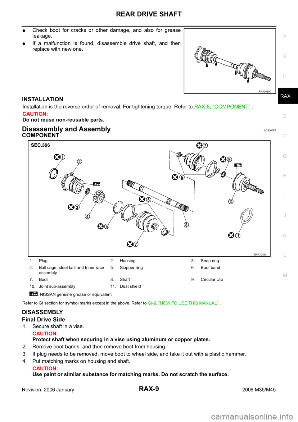
COMPONENT
Refer to GI section for symbol marks except in the above. Refer to GI-9, "HOW TO USE THIS MANUAL" .
DISASSEMBLY
Final Drive Side
1. Secure shaft in a vise.
CAUTION:
Protect shaft when securing in a vise using aluminum or copper plates.
2. Remove boot bands, and then remove boot from housing.
3. If plug needs to be removed, move boot to wheel side, and take it out with a plastic hammer.
4. Put matching marks on housing and shaft.
CAUTION:
Use paint or similar substance for matching marks. Do not scratch the surface.
RAA0030D
1. Plug 2. Housing 3. Snap ring
4. Ball cage, steel ball and Inner race
assembly5. Stopper ring 6. Boot band
7. Boot 8. Shaft 9. Circular clip
10. Joint sub-assembly 11. Dust shield
: NISSAN genuine grease or equivalent
SDIA3029J
Page 5009 of 5621
RAX-10
REAR DRIVE SHAFT
Revision: 2006 January2006 M35/M45
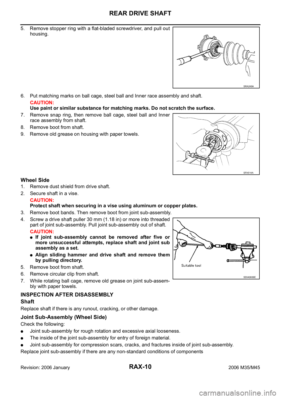
5. Remove stopper ring with a flat-bladed screwdriver, and pull out
housing.
6. Put matching marks on ball cage, steel ball and Inner race assembly and shaft.
CAUTION:
Use paint or similar substance for matching marks. Do not scratch the surface.
7. Remove snap ring, then remove ball cage, steel ball and Inner
race assembly from shaft.
8. Remove boot from shaft.
9. Remove old grease on housing with paper towels.
Wheel Side
1. Remove dust shield from drive shaft.
2. Secure shaft in a vise.
CAUTION:
Protect shaft when securing in a vise using aluminum or copper plates.
3. Remove boot bands. Then remove boot from joint sub-assembly.
4. Screw a drive shaft puller 30 mm (1.18 in) or more into threaded
part of joint sub-assembly. Pull joint sub-assembly out of shaft.
CAUTION:
If joint sub-assembly cannot be removed after five or
more unsuccessful attempts, replace shaft and joint sub
assembly as a set.
Align sliding hammer and drive shaft and remove them
by pulling directory.
5. Remove boot from shaft.
6. Remove circular clip from shaft.
7. While rotating ball cage, remove old grease on joint sub-assem-
bly with paper towels.
INSPECTION AFTER DISASSEMBLY
Shaft
Replace shaft if there is any runout, cracking, or other damage.
Joint Sub-Assembly (Wheel Side)
Check the following:
Joint sub-assembly for rough rotation and excessive axial looseness.
The inside of the joint sub-assembly for entry of foreign material.
Joint sub-assembly for compression scars, cracks, and fractures inside of joint sub-assembly.
Replace joint sub-assembly if there are any non-standard conditions of components
SRA249A
SFA514A
SDIA0606E
Page 5010 of 5621
REAR DRIVE SHAFT
RAX-11
C
E
F
G
H
I
J
K
L
MA
B
RAX
Revision: 2006 January2006 M35/M45
CAUTION:
If there are any irregular conditions of joint sub-assembly components, replace the entire joint sub-
assembly.
Final Drive Side
Make sure there are compression scars, cracks, fractures or unusual wear of ball rolling surface.
Make sure there is no damage to shaft screws.
Make sure there is no deformation of boot installation parts.
Ball Cage
Make sure there are compression scars, cracks, fractures of sliding surface.
Steel Ball
Make sure there are compression scars, cracks, fractures or unusual wear.
Inner Race
Check ball sliding surface for compression scars, cracks or fractures.
Make sure there is no damage to serrated part.
CAUTION:
If there are any irregular conditions in the component, replace with a new set of housing and the
ball cage, steel ball and inner race assembly.
ASSEMBLY
Final Drive Side
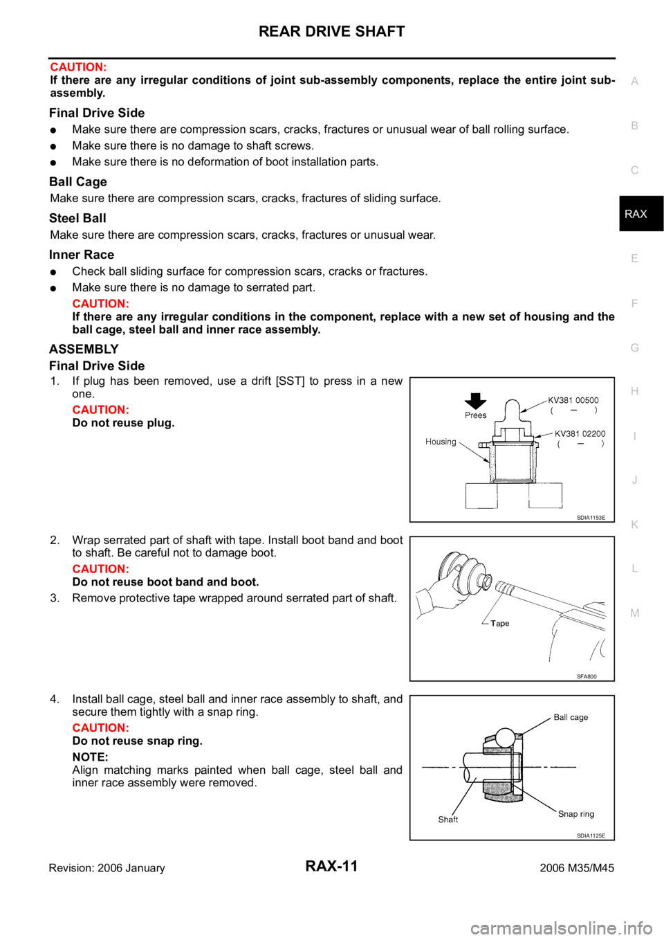
1. If plug has been removed, use a drift [SST] to press in a new
one.
CAUTION:
Do not reuse plug.
2. Wrap serrated part of shaft with tape. Install boot band and boot
to shaft. Be careful not to damage boot.
CAUTION:
Do not reuse boot band and boot.
3. Remove protective tape wrapped around serrated part of shaft.
4. Install ball cage, steel ball and inner race assembly to shaft, and
secure them tightly with a snap ring.
CAUTION:
Do not reuse snap ring.
NOTE:
Align matching marks painted when ball cage, steel ball and
inner race assembly were removed.
SDIA1153E
SFA800
SDIA1125E
Page 5011 of 5621
RAX-12
REAR DRIVE SHAFT
Revision: 2006 January2006 M35/M45
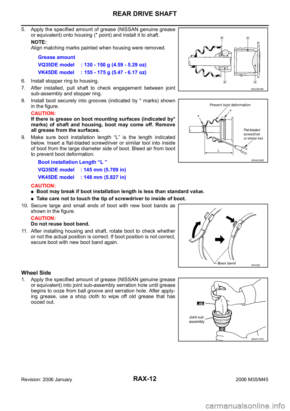
5. Apply the specified amount of grease (NISSAN genuine grease
or equivalent) onto housing (* point) and install it to shaft.
NOTE:
Align matching marks painted when housing were removed.
6. Install stopper ring to housing.
7. After installed, pull shaft to check engagement between joint
sub-assembly and stopper ring.
8. Install boot securely into grooves (indicated by * marks) shown
in the figure.
CAUTION:
If there is grease on boot mounting surfaces (indicated by*
marks) of shaft and housing, boot may come off. Remove
all grease from the surfaces.
9. Make sure boot installation length “L” is the length indicated
below. Insert a flat-bladed screwdriver or similar tool into inside
of boot from the large diameter side of boot. Bleed air from boot
to prevent boot deformation.
CAUTION:
Boot may break if boot installation length is less than standard value.
Take care not to touch the tip of screwdriver to inside of boot.
10. Secure large and small ends of boot with new boot bands as
shown in the figure.
CAUTION:
Do not reuse boot band.
11. After installing housing and shaft, rotate boot to check whether
or not the actual position is correct. If boot position is not correct,
secure boot with new boot band again.
Wheel Side
1. Apply the specified amount of grease (NISSAN genuine grease
or equivalent) into joint sub-assembly serration hole until grease
begins to ooze from ball groove and serration hole. After apply-
ing grease, use a shop cloth to wipe off old grease that has
oozed out.Grease amount
VQ35DE model : 130 - 150 g (4.59 - 5.29 oz)
VK45DE model : 155 - 175 g (5.47 - 6.17 oz)
Boot installation Length “L ”
VQ35DE model : 145 mm (5.709 in)
VK45DE model : 148 mm (5.827 in)
RAC0678D
SDIA3249E
SFA395
SDIA1127E
Page 5012 of 5621
REAR DRIVE SHAFT
RAX-13
C
E
F
G
H
I
J
K
L
MA
B
RAX
Revision: 2006 January2006 M35/M45
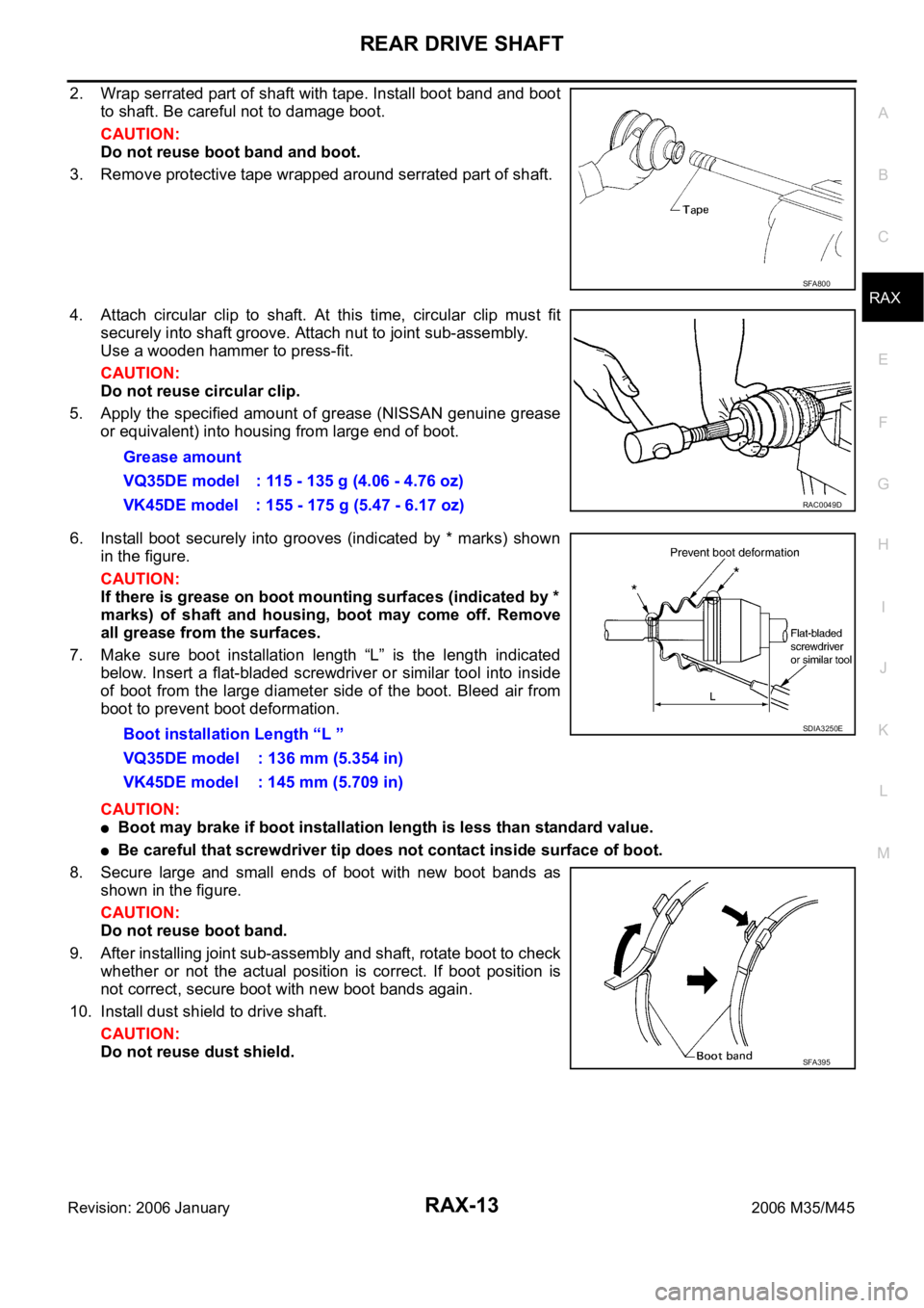
2. Wrap serrated part of shaft with tape. Install boot band and boot
to shaft. Be careful not to damage boot.
CAUTION:
Do not reuse boot band and boot.
3. Remove protective tape wrapped around serrated part of shaft.
4. Attach circular clip to shaft. At this time, circular clip must fit
securely into shaft groove. Attach nut to joint sub-assembly.
Use a wooden hammer to press-fit.
CAUTION:
Do not reuse circular clip.
5. Apply the specified amount of grease (NISSAN genuine grease
or equivalent) into housing from large end of boot.
6. Install boot securely into grooves (indicated by * marks) shown
in the figure.
CAUTION:
If there is grease on boot mounting surfaces (indicated by *
marks) of shaft and housing, boot may come off. Remove
all grease from the surfaces.
7. Make sure boot installation length “L” is the length indicated
below. Insert a flat-bladed screwdriver or similar tool into inside
of boot from the large diameter side of the boot. Bleed air from
boot to prevent boot deformation.
CAUTION:
Boot may brake if boot installation length is less than standard value.
Be careful that screwdriver tip does not contact inside surface of boot.
8. Secure large and small ends of boot with new boot bands as
shown in the figure.
CAUTION:
Do not reuse boot band.
9. After installing joint sub-assembly and shaft, rotate boot to check
whether or not the actual position is correct. If boot position is
not correct, secure boot with new boot bands again.
10. Install dust shield to drive shaft.
CAUTION:
Do not reuse dust shield.
SFA800
Grease amount
VQ35DE model : 115 - 135 g (4.06 - 4.76 oz)
VK45DE model : 155 - 175 g (5.47 - 6.17 oz)
RAC0049D
Boot installation Length “L ”
VQ35DE model : 136 mm (5.354 in)
VK45DE model : 145 mm (5.709 in)SDIA3250E
SFA395
Page 5018 of 5621
SQUEAK AND RATTLE TROUBLE DIAGNOSES
RF-5
C
D
E
F
G
H
J
K
L
MA
B
RF
Revision: 2006 January2006 M35/M45
DUPLICATE THE NOISE AND TEST DRIVE
If possible, drive the vehicle with the customer until the noise is duplicated. Note any additional information on
the Diagnostic Worksheet regarding the conditions or location of the noise. This information can be used to
duplicate the same conditions when you confirm the repair.
If the noise can be duplicated easily during the test drive, to help identify the source of the noise, try to dupli-
cate the noise with the vehicle stopped by doing one or all of the following:
1) Close a door.
2) Tap or push/pull around the area where the noise appears to be coming from.
3) Rev the engine.
4) Use a floor jack to recreate vehicle “twist”.
5) At idle, apply engine load (electrical load, half-clutch on M/T models, drive position on A/T models).
6) Raise the vehicle on a hoist and hit a tire with a rubber hammer.
Drive the vehicle and attempt to duplicate the conditions the customer states exist when the noise occurs.
If it is difficult to duplicate the noise, drive the vehicle slowly on an undulating or rough road to stress the
vehicle body.
CHECK RELATED SERVICE BULLETINS
After verifying the customer concern or symptom, check ASIST for Technical Service Bulletins (TSBs) related
to that concern or symptom.
If a TSB relates to the symptom, follow the procedure to repair the noise.
LOCATE THE NOISE AND IDENTIFY THE ROOT CAUSE
1. Narrow down the noise to a general area. To help pinpoint the source of the noise, use a listening tool
(Chassis Ear: J-39570, Engine Ear and mechanics stethoscope).
2. Narrow down the noise to a more specific area and identify the cause of the noise by:
removing the components in the area that you suspect the noise is coming from.
Do not use too much force when removing clips and fasteners, otherwise clips and fastener can be broken
or lost during the repair, resulting in the creation of new noise.
tapping or pushing/pulling the component that you suspect is causing the noise.
Do not tap or push/pull the component with excessive force, otherwise the noise will be eliminated only
temporarily.
feeling for a vibration with your hand by touching the component(s) that you suspect is (are) causing the
noise.
placing a piece of paper between components that you suspect are causing the noise.
looking for loose components and contact marks.
Refer to RF-6, "
Generic Squeak and Rattle Troubleshooting" .
REPAIR THE CAUSE
If the cause is a loose component, tighten the component securely.
If the cause is insufficient clearance between components:
–separate components by repositioning or loosening and retightening the component, if possible.
–insulate components with a suitable insulator such as urethane pads, foam blocks, felt cloth tape or ure-
thane tape. A Nissan Squeak and Rattle Kit (J-43980) is available through your authorized Nissan Parts
Department.
CAUTION:
Do not use excessive force as many components are constructed of plastic and may be damaged.
NOTE:
Always check with the Parts Department for the latest parts information.
The following materials are contained in the Nissan Squeak and Rattle Kit (J-43980). Each item can be
ordered separately as needed.
URETHANE PADS [1.5 mm (0.059 in) thick]
Insulates connectors, harness, etc.
76268-9E005: 100
135 mm (3.945.31 in)/76884-71L01: 6085 mm (2.363.35 in)/76884-
71L02: 15
25 mm (0.590.98 in)
INSULATOR (Foam blocks)
Insulates components from contact. Can be used to fill space behind a panel.
73982-9E000: 45 mm (1.77 in) thick, 50
50 mm (1.971.97 in)/73982-50Y00:
10 mm (0.39 in) thick, 50
50 mm (1.971.97 in)
Page 5020 of 5621
SQUEAK AND RATTLE TROUBLE DIAGNOSES
RF-7
C
D
E
F
G
H
J
K
L
MA
B
RF
Revision: 2006 January2006 M35/M45
TRUNK
Trunk noises are often caused by a loose jack or loose items put into the trunk by the owner.
In addition look for:
1. Trunk lid dumpers out of adjustment
2. Trunk lid striker out of adjustment
3. The trunk lid torsion bars knocking together
4. A loose license plate or bracket
Most of these incidents can be repaired by adjusting, securing or insulating the item(s) or component(s) caus-
ing the noise.
SUNROOF/HEADLINING
Noises in the sunroof/headlining area can often be traced to one of the following:
1. Sunroof lid, rail, linkage or seals making a rattle or light knocking noise
2. Sunvisor shaft shaking in the holder
3. Front or rear windshield touching headlining and squeaking
Again, pressing on the components to stop the noise while duplicating the conditions can isolate most of these
incidents. Repairs usually consist of insulating with felt cloth tape.
SEATS
When isolating seat noise it's important to note the position the seat is in and the load placed on the seat when
the noise is present. These conditions should be duplicated when verifying and isolating the cause of the
noise.
Cause of seat noise include:
1. Headrest rods and holder
2. A squeak between the seat pad cushion and frame
3. The rear seatback lock and bracket
These noises can be isolated by moving or pressing on the suspected components while duplicating the con-
ditions under which the noise occurs. Most of these incidents can be repaired by repositioning the component
or applying urethane tape to the contact area.
UNDERHOOD
Some interior noise may be caused by components under the hood or on the engine wall. The noise is then
transmitted into the passenger compartment.
Causes of transmitted underhood noise include:
1. Any component mounted to the engine wall
2. Components that pass through the engine wall
3. Engine wall mounts and connectors
4. Loose radiator mounting pins
5. Hood bumpers out of adjustment
6. Hood striker out of adjustment
These noises can be difficult to isolate since they cannot be reached from the interior of the vehicle. The best
method is to secure, move or insulate one component at a time and test drive the vehicle. Also, engine RPM
or load can be changed to isolate the noise. Repairs can usually be made by moving, adjusting, securing, or
insulating the component causing the noise.
Page 5040 of 5621
SUNROOF
RF-27
C
D
E
F
G
H
J
K
L
MA
B
RF
Revision: 2006 January2006 M35/M45
SUNROOF UNIT
Removal
CAUTION:
Always work with a helper.
When taking sunroof unit out, use clothes to protect the seats and trim from damage.
After installing the sunroof unit and glass lid, be sure to carry out the leak test and check that
there is no malfunction.
1. Remove the headlining. Refer to EI-52, "
HEADLINING" .
2. Disconnect drain hoses.
3. Tilt up glass lid, and then remove glass lid.
4. Remove sunroof motor assembly mounting screws. Disconnect connector from sunroof motor assembly
and then remove sunroof motor assembly.
CAUTION:
Before removing sunroof motor, make sure that sunroof lid is fully closed.
After removing sunroof motor, do not attempt to rotate sunroof motor assembly as a single unit.
5. Remove nuts from the front end and side rail.
6. Remove front sunroof bracket bolts.
7. Remove rear sunroof bracket bolts, and then remove sunroof unit assembly from roof panel.
8. Remove sunroof unit assembly through the passenger compartment while being careful not to damage
the seats and trim.
Installation
1. Temporarily tighten the mounting bolts to the rear sunroof brackets (RH/LH).
2. Bring sunroof unit into passenger compartment, and then place the rear end of the rail onto the rear sun-
roof brackets.
3. Temporarily tighten the mounting nuts to the front end of sunroof unit assembly.
4. Tighten the installation points diagonally excluding the installation point of the sunroof bracket around the
roof opening.
5. Tighten the front sunroof bracket bolts of the vehicle side, and then tighten the bolt of the rail side.
6. Tighten the rear sunroof bracket bolts of the vehicle side, and then tighten the bolt of the rail side.
7. Tighten the mounting nuts to the front end and side rail.
8. Move the sunroof motor assembly laterally by little by little so that the gear is completely engaged into the
wire on the sunroof unit assembly and mounting surface becomes parallel. Then secure the sunroof motor
assembly with screws.
CAUTION:
Before installing the sunroof motor assembly, be sure to the place the link and wire assembly in
the symmetrical and fully closed position.
9. Install glass lid.
NOTE:
After installation, carry out fitting adjustment.
10. Connect drain hoses.
11. Install headlining. Refer to EI-52, "
HEADLINING" .
4. Sunroof motor assembly 5. Front sunroof bracket (LH/RH) 6. Rear sunroof bracket (LH/RH)
7. Sunroof unit assembly
Page 5060 of 5621
REAR FINAL DRIVE ASSEMBLY
RFD-17
C
E
F
G
H
I
J
K
L
MA
B
RFD
Revision: 2006 January2006 M35/M45
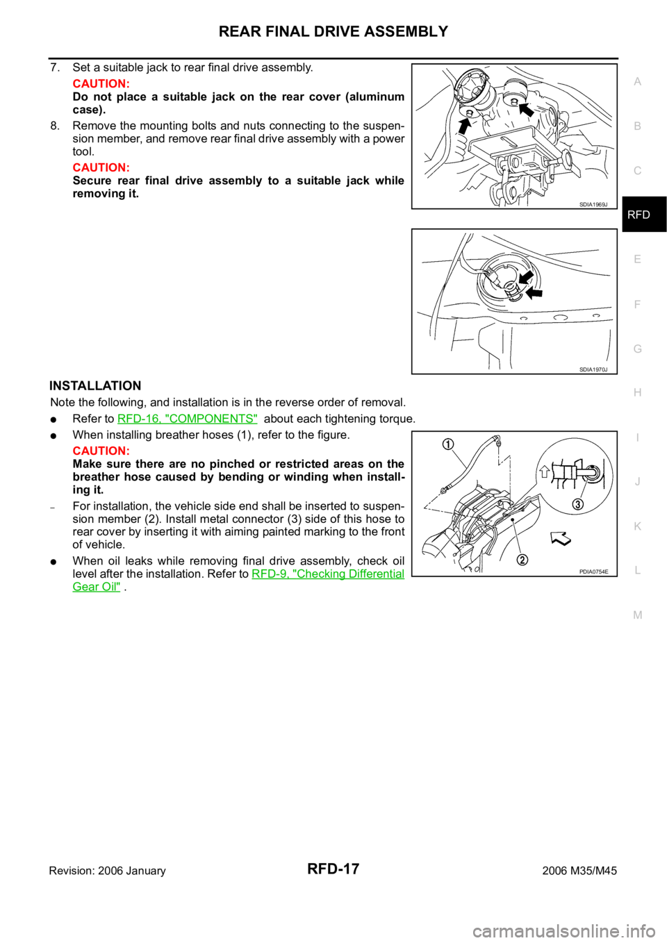
7. Set a suitable jack to rear final drive assembly.
CAUTION:
Do not place a suitable jack on the rear cover (aluminum
case).
8. Remove the mounting bolts and nuts connecting to the suspen-
sion member, and remove rear final drive assembly with a power
tool.
CAUTION:
Secure rear final drive assembly to a suitable jack while
removing it.
INSTALLATION
Note the following, and installation is in the reverse order of removal.
Refer to RFD-16, "COMPONENTS" about each tightening torque.
When installing breather hoses (1), refer to the figure.
CAUTION:
Make sure there are no pinched or restricted areas on the
breather hose caused by bending or winding when install-
ing it.
–For installation, the vehicle side end shall be inserted to suspen-
sion member (2). Install metal connector (3) side of this hose to
rear cover by inserting it with aiming painted marking to the front
of vehicle.
When oil leaks while removing final drive assembly, check oil
level after the installation. Refer to RFD-9, "
Checking Differential
Gear Oil" .
SDIA1969J
SDIA1970J
PDIA0754E