Panel INFINITI M35 2006 Factory Manual PDF
[x] Cancel search | Manufacturer: INFINITI, Model Year: 2006, Model line: M35, Model: INFINITI M35 2006Pages: 5621, PDF Size: 65.56 MB
Page 1283 of 5621
BR-8
BRAKE PEDAL
Revision: 2006 January2006 M35/M45
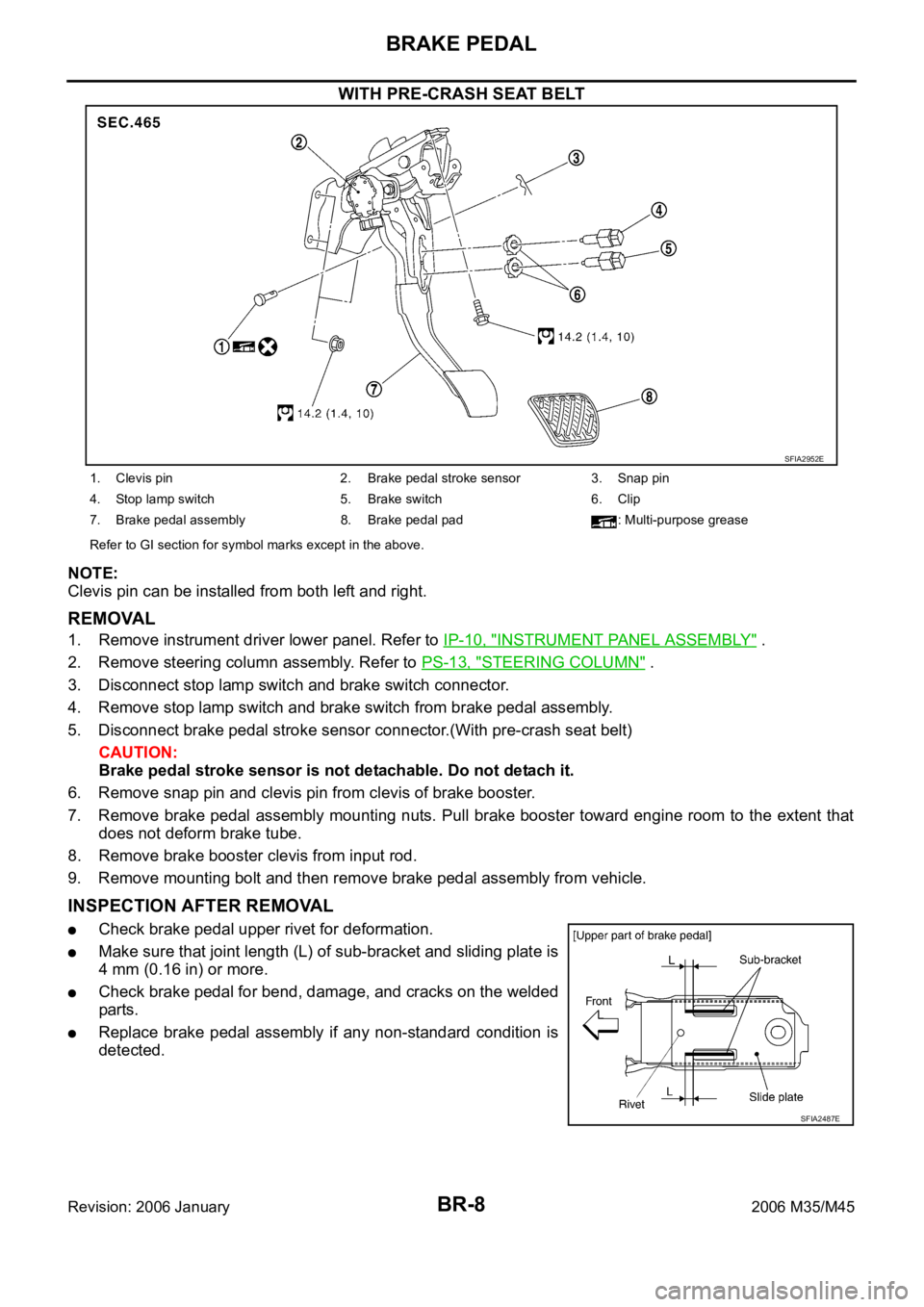
WITH PRE-CRASH SEAT BELT
NOTE:
Clevis pin can be installed from both left and right.
REMOVAL
1. Remove instrument driver lower panel. Refer to IP-10, "INSTRUMENT PANEL ASSEMBLY" .
2. Remove steering column assembly. Refer to PS-13, "
STEERING COLUMN" .
3. Disconnect stop lamp switch and brake switch connector.
4. Remove stop lamp switch and brake switch from brake pedal assembly.
5. Disconnect brake pedal stroke sensor connector.(With pre-crash seat belt)
CAUTION:
Brake pedal stroke sensor is not detachable. Do not detach it.
6. Remove snap pin and clevis pin from clevis of brake booster.
7. Remove brake pedal assembly mounting nuts. Pull brake booster toward engine room to the extent that
does not deform brake tube.
8. Remove brake booster clevis from input rod.
9. Remove mounting bolt and then remove brake pedal assembly from vehicle.
INSPECTION AFTER REMOVAL
Check brake pedal upper rivet for deformation.
Make sure that joint length (L) of sub-bracket and sliding plate is
4 mm (0.16 in) or more.
Check brake pedal for bend, damage, and cracks on the welded
parts.
Replace brake pedal assembly if any non-standard condition is
detected.
SFIA2952E
1. Clevis pin 2. Brake pedal stroke sensor 3. Snap pin
4. Stop lamp switch 5. Brake switch 6. Clip
7. Brake pedal assembly 8. Brake pedal pad : Multi-purpose grease
Refer to GI section for symbol marks except in the above.
SFIA2487E
Page 1293 of 5621
BR-18
BRAKE BOOSTER
Revision: 2006 January2006 M35/M45
BRAKE BOOSTERPFP:47200
On-Board Inspection and ServiceNFS000P6
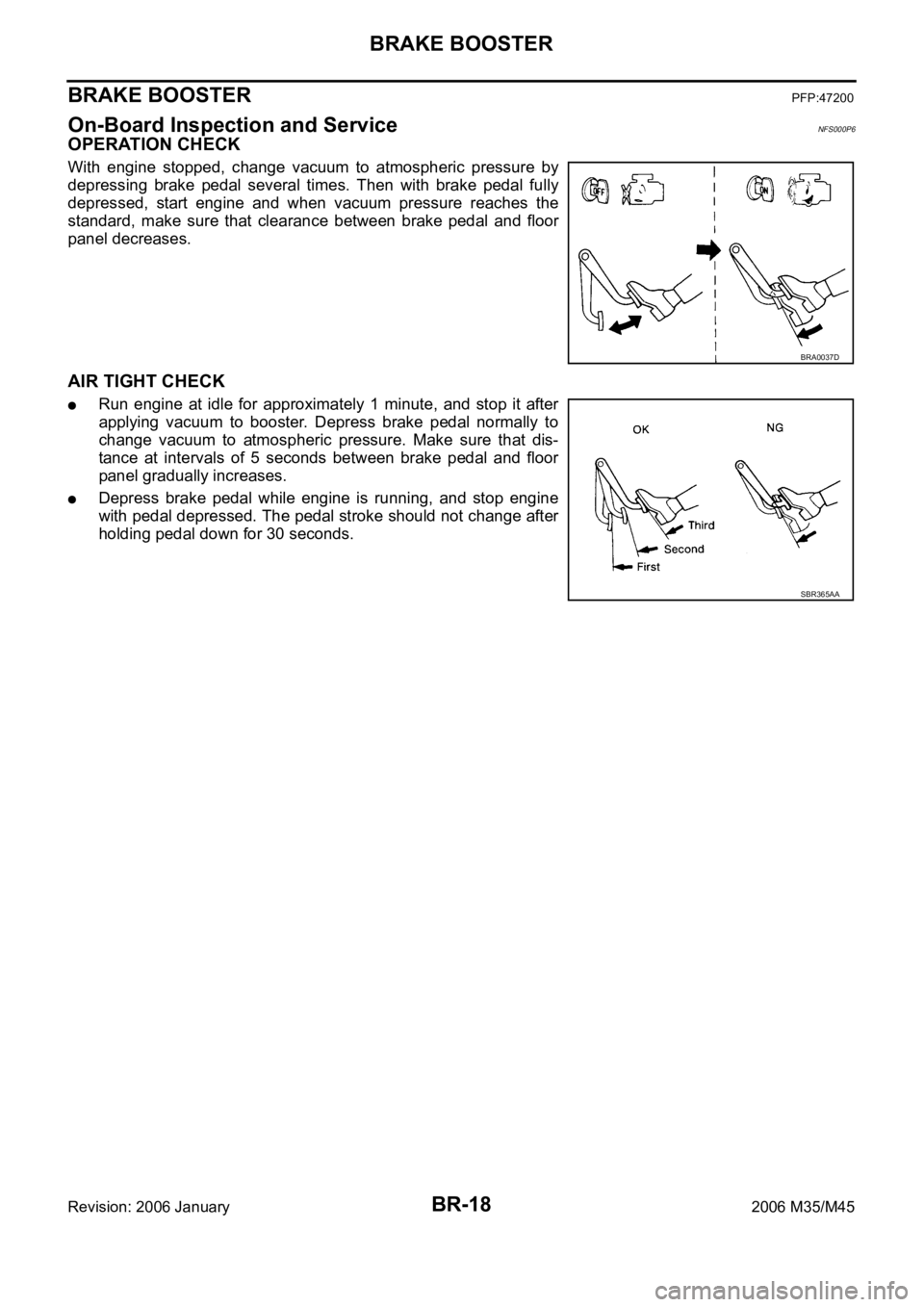
OPERATION CHECK
With engine stopped, change vacuum to atmospheric pressure by
depressing brake pedal several times. Then with brake pedal fully
depressed, start engine and when vacuum pressure reaches the
standard, make sure that clearance between brake pedal and floor
panel decreases.
AIR TIGHT CHECK
Run engine at idle for approximately 1 minute, and stop it after
applying vacuum to booster. Depress brake pedal normally to
change vacuum to atmospheric pressure. Make sure that dis-
tance at intervals of 5 seconds between brake pedal and floor
panel gradually increases.
Depress brake pedal while engine is running, and stop engine
with pedal depressed. The pedal stroke should not change after
holding pedal down for 30 seconds.
BRA0037D
SBR365AA
Page 1294 of 5621
BRAKE BOOSTER
BR-19
C
D
E
G
H
I
J
K
L
MA
B
BR
Revision: 2006 January2006 M35/M45
Removal and InstallationNFS000P7
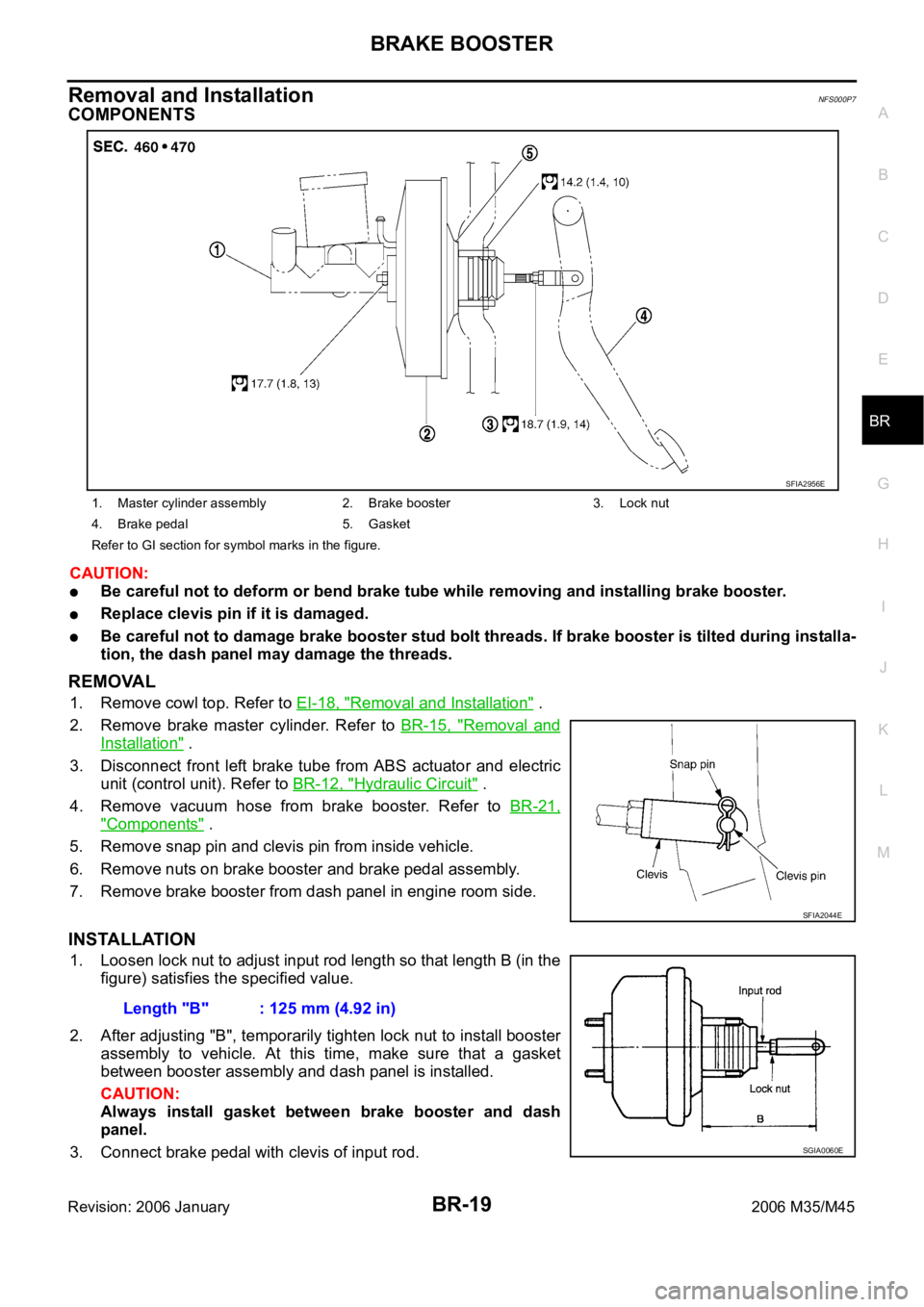
COMPONENTS
CAUTION:
Be careful not to deform or bend brake tube while removing and installing brake booster.
Replace clevis pin if it is damaged.
Be careful not to damage brake booster stud bolt threads. If brake booster is tilted during installa-
tion, the dash panel may damage the threads.
REMOVAL
1. Remove cowl top. Refer to EI-18, "Removal and Installation" .
2. Remove brake master cylinder. Refer to BR-15, "
Removal and
Installation" .
3. Disconnect front left brake tube from ABS actuator and electric
unit (control unit). Refer to BR-12, "
Hydraulic Circuit" .
4. Remove vacuum hose from brake booster. Refer to BR-21,
"Components" .
5. Remove snap pin and clevis pin from inside vehicle.
6. Remove nuts on brake booster and brake pedal assembly.
7. Remove brake booster from dash panel in engine room side.
INSTALLATION
1. Loosen lock nut to adjust input rod length so that length B (in the
figure) satisfies the specified value.
2. After adjusting "B", temporarily tighten lock nut to install booster
assembly to vehicle. At this time, make sure that a gasket
between booster assembly and dash panel is installed.
CAUTION:
Always install gasket between brake booster and dash
panel.
3. Connect brake pedal with clevis of input rod.
1. Master cylinder assembly 2. Brake booster 3. Lock nut
4. Brake pedal 5. Gasket
Refer to GI section for symbol marks in the figure.
SFIA2956E
SFIA2044E
Length "B" : 125 mm (4.92 in)
SGIA0060E
Page 1310 of 5621

SERVICE DATA AND SPECIFICATIONS (SDS)
BR-35
C
D
E
G
H
I
J
K
L
MA
B
BR
Revision: 2006 January2006 M35/M45
SERVICE DATA AND SPECIFICATIONS (SDS)PFP:00030
General SpecificationsNFS000PL
Unit: mm (in)
Brake PedalNFS000PM
Brake BoosterNFS000PN
Va c u u m t y p e
Check ValveNFS000PO
Front Disc BrakeNFS000PP
Front brake Brake model CLZ31VD, CLZ31VB
Cylinder bore diameter 45 (1.772)
2
Pad length
width thickness 132 50 11 (5.20 1.969 0.433)
Rotor outer diameter
thickness 320 28 (12.60 1.10)
Rear brake Brake model AD14VF, AD14VE
Cylinder bore diameter 42.86 (1.687)
Pad length
width thickness 83.0 31.9 8.5 (3.268 1.256 0.335)
Rotor outer diameter
thickness 308 16 (12.13 0.63)
Master cylinder Cylinder bore diameter 25.4 (1)
Control valve Valve model Electric brake force distribution
Brake boosterBooster model N255
Diaphragm diameter 255 (10)
Recommended brake fluid DOT 3
Brake pedal height (from dash lower panel top surface) 157 167 mm (6.18 6.57 in)
Depressed pedal height
[under a force of 490 N (50 kg, 110 lb) with engine running]90 mm (3.54 in) or more
Clearance between threaded end of the stop lamp switch/brake switch
and bracket 0.74 - 1.96 mm (0.0291 - 0.0772 in)
Pedal play3 - 11 mm (0.12 - 0.43 in)
Input rod installation standard dimension 125 mm (4.92 in)
Vacuum leakage
[at vacuum of – 66.7 kPa (– 500 mmHg, – 19.69 inHg)]Within 1.3 kPa (10 mmHg, 0.39 inHg) of vacuum for 15 seconds
Brake modelCLZ31VD, CLZ31VB
Brake padStandard thickness 11.0 mm (0.433 in)
Repair limit thickness 2.0 mm (0.079 in)
Disc rotorStandard thickness 28.0 mm (1.102 in)
Wear limit 26.0 mm (1.024 in)
Thickness variation (measured at 8 positions) 0.015 mm (0.0006 in)
Runout limit (with it attached to the vehicle) 0.035 mm (0.0014 in)
Page 1371 of 5621
![INFINITI M35 2006 Factory Manual PDF BRC-60
[VDC/TCS/ABS]
ACTUATOR AND ELECTRIC UNIT (ASSEMBLY)
Revision: 2006 January2006 M35/M45
ACTUATOR AND ELECTRIC UNIT (ASSEMBLY)PFP:47660
Removal and InstallationNFS000RC
COMPONENT
CAUTION:
Be care INFINITI M35 2006 Factory Manual PDF BRC-60
[VDC/TCS/ABS]
ACTUATOR AND ELECTRIC UNIT (ASSEMBLY)
Revision: 2006 January2006 M35/M45
ACTUATOR AND ELECTRIC UNIT (ASSEMBLY)PFP:47660
Removal and InstallationNFS000RC
COMPONENT
CAUTION:
Be care](/img/42/57023/w960_57023-1370.png)
BRC-60
[VDC/TCS/ABS]
ACTUATOR AND ELECTRIC UNIT (ASSEMBLY)
Revision: 2006 January2006 M35/M45
ACTUATOR AND ELECTRIC UNIT (ASSEMBLY)PFP:47660
Removal and InstallationNFS000RC
COMPONENT
CAUTION:
Be careful of the following.
Before servicing, disconnect the battery cable from negative terminal.
To remove brake tube, use a flare nut wrench to prevent flare nuts and brake tube from being dam-
aged. To install, use flare nut torque wrench.
Do not apply excessive impact to ABS actuator and electric unit (control unit), such as dropping it.
Do not remove and install actuator by holding harness.
After work is completed, bleed air from brake tube. Refer to BR-11, "Bleeding Brake System" .
After installing harness connector in the ABS actuator and electric unit (control unit), make sure
connector is securely locked.
REMOVAL
1. Remove cowl top cover. Refer to EI-18, "REMOVAL" .
2. Disconnect ABS actuator and electric unit (control unit) connector.
3. Loosen brake tube flare nuts, then remove brake tubes from ABS actuator and electric unit (control unit).
4. Remove tire.
5. Remove fender protector (rear): (front LH side). Refer to EI-20, "
REMOVAL" .
6. Remove ABS actuator and electric unit (control unit) bracket mounting nut.
1. ABS actuator and electric unit (con-
trol unit)2. Connector 3. To front RH brake caliper
4. To rear LH brake caliper 5. To rear RH brake caliper 6. To front LH brake caliper
7. From master cylinder primary side 8. From master cylinder secondary side 9. Bushing
10. Bracket A. Left side of dash panel
Refer to GI section GI-11, "
Components" for symbol marks in the figure.
SFIA3018E
Page 1460 of 5621
COMBINATION METERS
DI-27
C
D
E
F
G
H
I
J
L
MA
B
DI
Revision: 2006 January2006 M35/M45
Removal and Installation of Combination MeterNKS003UE
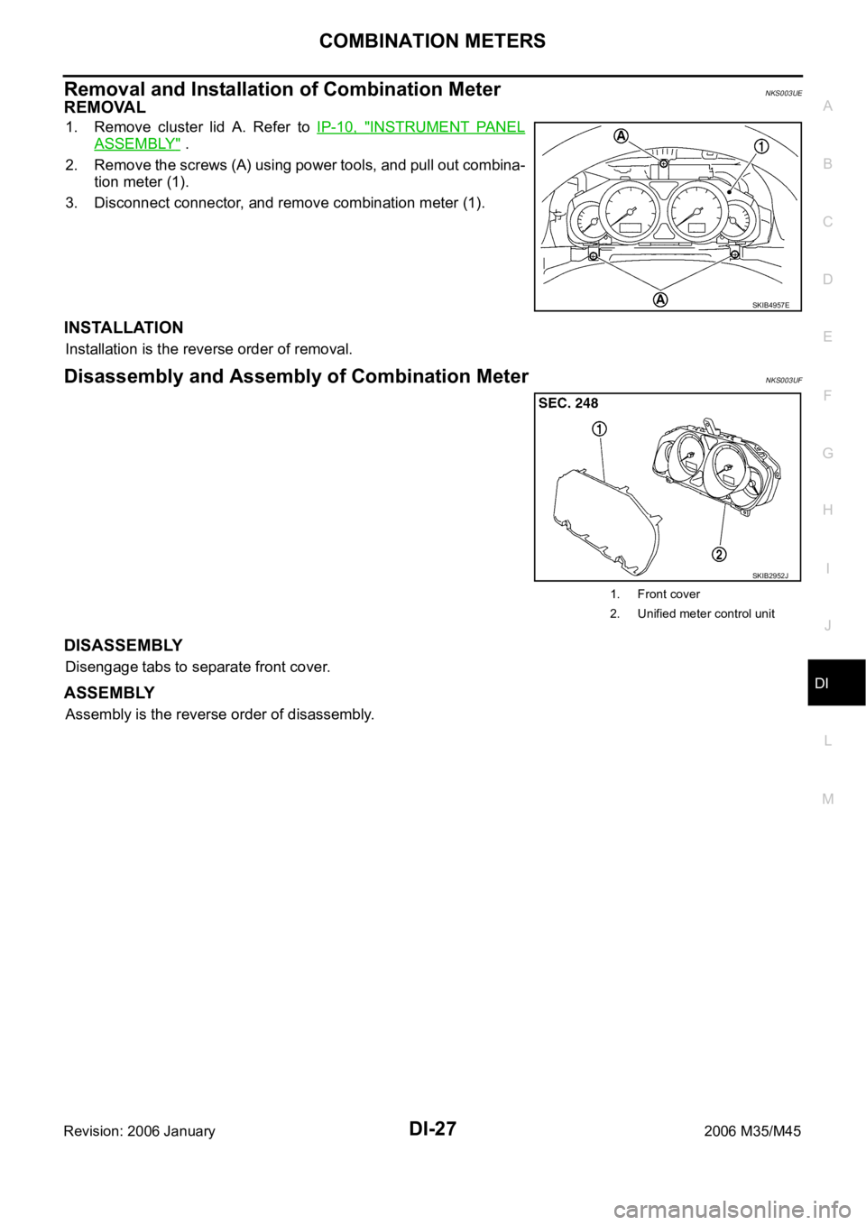
REMOVAL
1. Remove cluster lid A. Refer to IP-10, "INSTRUMENT PANEL
ASSEMBLY" .
2. Remove the screws (A) using power tools, and pull out combina-
tion meter (1).
3. Disconnect connector, and remove combination meter (1).
INSTALLATION
Installation is the reverse order of removal.
Disassembly and Assembly of Combination MeterNKS003UF
DISASSEMBLY
Disengage tabs to separate front cover.
ASSEMBLY
Assembly is the reverse order of disassembly.
SKIB4957E
SKIB2952J
1. Front cover
2. Unified meter control unit
Page 1511 of 5621

DI-78
LANE DEPARTURE WARNING SYSTEM
Revision: 2006 January2006 M35/M45
LANE DEPARTURE WARNING SYSTEM PFP:28442
Precautions for Lane Departure Warning (LDW) systemNKS003VF
WAR NING :
Lane Departure Warning (LDW) is only a warning device to inform the driver of an unintended lane
departure. It will not steer the vehicle or prevent loss of control. It is the driver's responsibility to stay
alert, drive safely, keep the vehicle in the traveling lane, and be in control of the vehicle at all times.
LDW system does not operate under the following conditions:
–At speeds below approx. 72 km/h (45 MPH).
–If it cannot detect lane markers.
LDW system may not function properly under the following conditions:
–On roads where a water puddle, dirt or snow is covering the lane markers.
–On roads where the lane markers are faded or are not painted clearly.
–On roads where the lane markers are painted yellow.
LDW system may not monitor the lane markers in certain road, weather or driving conditions.
–On roads where there are sharp curves.
–Where the traveling lane merges or separates.
–On roads where the discontinued lane markers are present, such as near tollgates, etc.
–On roads where there are not general lane markers.
–On roads where the lane width is too narrow.
–During bad weather (rain, fog, snow, etc.).
–When strong light (for example, at sunrise or sunset) is directly shining on the front of the vehicle.
–When entering or exiting a tunnel where sudden changes in brightness occur.
–When traveling close to the vehicle in front of you, which causes obstruction of the camera unit
range.
–When the vehicle's traveling direction does not align with the lane marker.
–When rain, snow or dirt adhere to the windshield in front of the camera unit.
Excessive noise interferes with warning system chime sound and the chime may not be heard.
CAUTION:
To keep the LDW system operating properly, be sure to observe the following:
Always keep the windshield clean. The sensing capability of the camera unit depends on the con-
dition of the windshield. See “Appearance and care” for cleaning instruction.
Never strike or damage the areas around the camera unit.
Never touch the camera lens.
Never attach a sticker (including transparent material) or install an accessory near the camera
unit.
Never place reflective materials, such as a white paper or mirrors on the instrument panel. Reflec-
tion of the sunlight may adversely affect the camera unit's lane marker detection capability.
System DescriptionNKS003VG
LDW SYSTEM OPERATION
The Lane Departure Warning (LDW) system warns the driver when the vehicle is traveling close to either
the left or the right of the traveling lane.
The system monitors lane markers of the traveling lane using the LDW camera unit. When the LDW cam-
era unit detects that the vehicle is traveling close to either the left or the right of the traveling lane, the
LDW indicator lamp flashes and a chime sounds to alert the driver.
NOTE:
When activating turn signal, LDW system does not give a warning to the lane marker on the turn signal
side.
The LDW system can be turned on or off by pushing the LDW switch. When the system is on, the LDW
system ON indicator illuminates.
The LDW system has an automatic mode and manual mode.
Page 1514 of 5621
LANE DEPARTURE WARNING SYSTEM
DI-81
C
D
E
F
G
H
I
J
L
MA
B
DI
Revision: 2006 January2006 M35/M45
Camera Aiming AdjustmentNKS003VI
OUTLINE
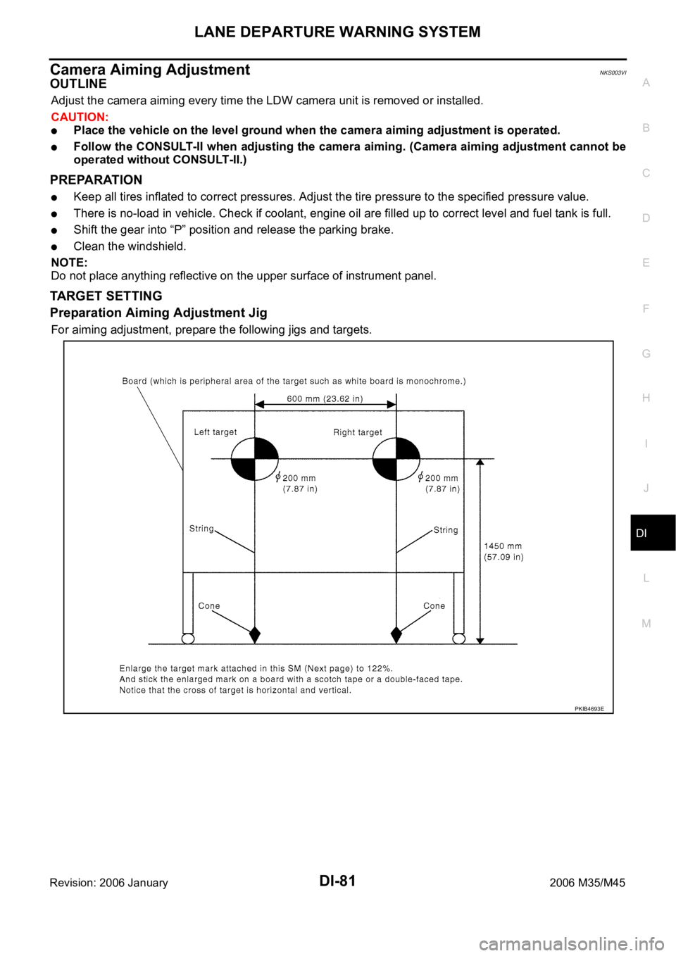
Adjust the camera aiming every time the LDW camera unit is removed or installed.
CAUTION:
Place the vehicle on the level ground when the camera aiming adjustment is operated.
Follow the CONSULT-II when adjusting the camera aiming. (Camera aiming adjustment cannot be
operated without CONSULT-II.)
PREPARATION
Keep all tires inflated to correct pressures. Adjust the tire pressure to the specified pressure value.
There is no-load in vehicle. Check if coolant, engine oil are filled up to correct level and fuel tank is full.
Shift the gear into “P” position and release the parking brake.
Clean the windshield.
NOTE:
Do not place anything reflective on the upper surface of instrument panel.
TARGET SETTING
Preparation Aiming Adjustment Jig
For aiming adjustment, prepare the following jigs and targets.
PKIB4693E
Page 1537 of 5621
DI-104
LANE DEPARTURE WARNING SYSTEM
Revision: 2006 January2006 M35/M45
Removal and Installation for LDW ChimeNKS003W1
REMOVAL
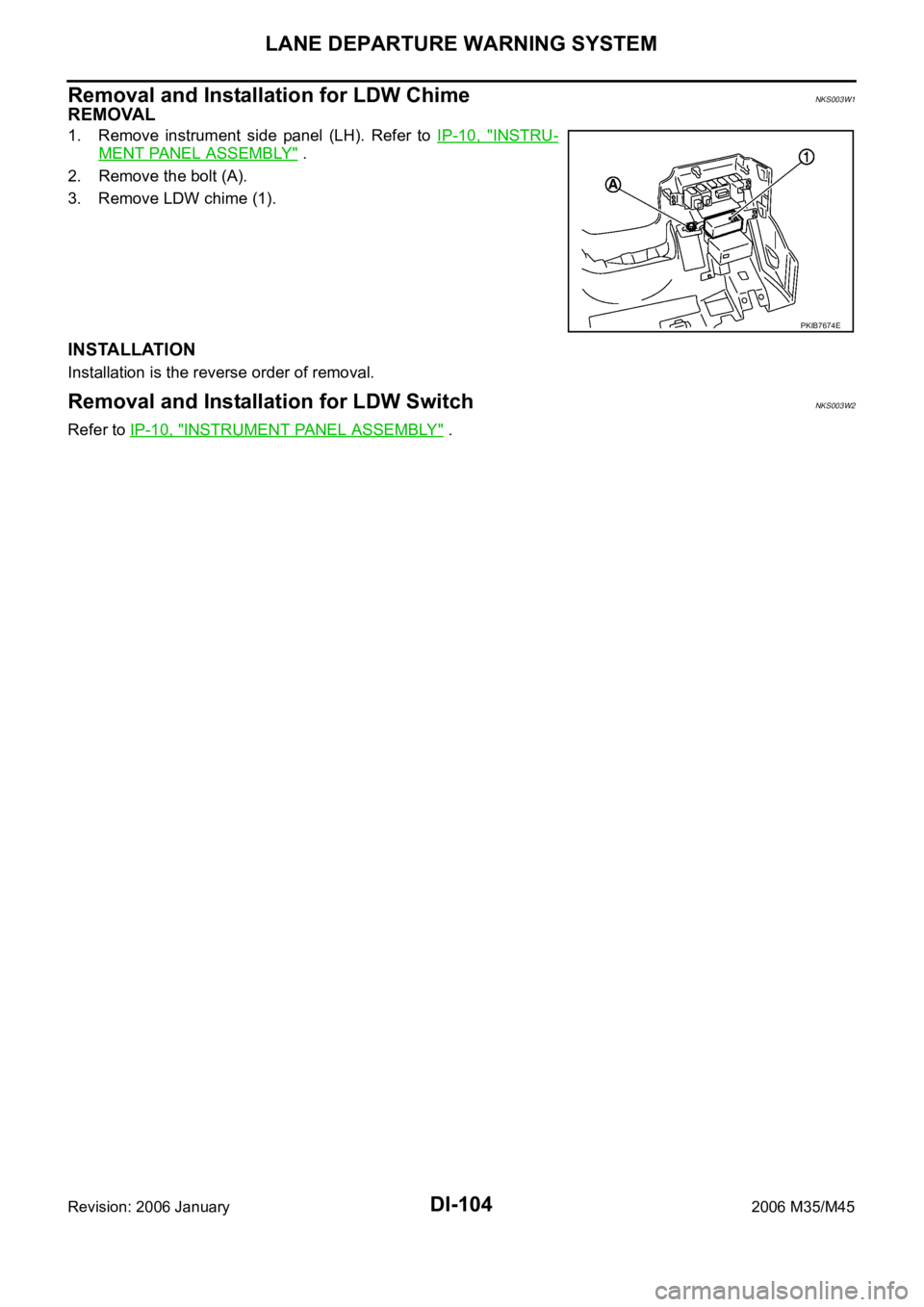
1. Remove instrument side panel (LH). Refer to IP-10, "INSTRU-
MENT PANEL ASSEMBLY" .
2. Remove the bolt (A).
3. Remove LDW chime (1).
INSTALLATION
Installation is the reverse order of removal.
Removal and Installation for LDW SwitchNKS003W2
Refer to IP-10, "INSTRUMENT PANEL ASSEMBLY" .
PKIB7674E
Page 1597 of 5621
![INFINITI M35 2006 Factory Manual PDF EC-54
[VQ35DE]
ON BOARD DIAGNOSTIC (OBD) SYSTEM
Revision: 2006 January2006 M35/M45
ON BOARD DIAGNOSTIC (OBD) SYSTEMPFP:00028
IntroductionNBS004SL
The ECM has an on board diagnostic system, which detec INFINITI M35 2006 Factory Manual PDF EC-54
[VQ35DE]
ON BOARD DIAGNOSTIC (OBD) SYSTEM
Revision: 2006 January2006 M35/M45
ON BOARD DIAGNOSTIC (OBD) SYSTEMPFP:00028
IntroductionNBS004SL
The ECM has an on board diagnostic system, which detec](/img/42/57023/w960_57023-1596.png)
EC-54
[VQ35DE]
ON BOARD DIAGNOSTIC (OBD) SYSTEM
Revision: 2006 January2006 M35/M45
ON BOARD DIAGNOSTIC (OBD) SYSTEMPFP:00028
IntroductionNBS004SL
The ECM has an on board diagnostic system, which detects malfunctions related to engine sensors or actua-
tors. The ECM also records various emission-related diagnostic information including:
The above information can be checked using procedures listed in the table below.
: Applicable —: Not applicable
*: When DTC and 1st trip DTC simultaneously appear on the display, they cannot be clearly distinguished from each other.
The malfunction indicator lamp (MIL) on the instrument panel lights up when the same malfunction is detected
in two consecutive trips (Two trip detection logic), or when the ECM enters fail-safe mode. (Refer to EC-108,
"Fail-Safe Chart" .)
Two Trip Detection LogicNBS004SM
When a malfunction is detected for the first time, 1st trip DTC and 1st trip Freeze Frame data are stored in the
ECM memory. The MIL will not light up at this stage. <1st trip>
If the same malfunction is detected again during the next drive, the DTC and Freeze Frame data are stored in
the ECM memory, and the MIL lights up. The MIL lights up at the same time when the DTC is stored. <2nd
trip> The “trip” in the “Two Trip Detection Logic” means a driving mode in which self-diagnosis is performed
during vehicle operation. Specific on board diagnostic items will cause the ECM to light up or blink the MIL,
and store DTC and Freeze Frame data, even in the 1st trip, as shown below.
: Applicable —: Not applicable
When there is an open circuit on MIL circuit, the ECM cannot warn the driver by lighting up MIL when there is
malfunction on engine control system.
Emission-related diagnostic information Diagnostic service
Diagnostic Trouble Code (DTC) Service $03 of SAE J1979
Freeze Frame data Service $02 of SAE J1979
System Readiness Test (SRT) code Service $01 of SAE J1979
1st Trip Diagnostic Trouble Code (1st Trip DTC) Service $07 of SAE J1979
1st Trip Freeze Frame data
Test values and Test limits Service $06 of SAE J1979
Calibration ID Service $09 of SAE J1979
DTC 1st trip DTCFreeze
Frame data1st trip Freeze
Frame dataSRT code SRT status Test value
CONSULT-II
—
GST
—
ECM*— — ——
ItemsMIL DTC 1st trip DTC
1st trip 2nd trip
1st trip
displaying2nd trip
displaying1st trip
displaying2nd trip
display-
ing BlinkingLighting
upBlinkingLighting
up
Misfire (Possible three way cata-
lyst damage) — DTC: P0300 -
P0306 is being detected
———— ——
Misfire (Possible three way cata-
lyst damage) — DTC: P0300 -
P0306 is being detected——
————
One trip detection diagnoses
(Refer to EC-55, "
EMISSION-
RELATED DIAGNOSTIC INFOR-
MATION ITEMS" .)—
—————
Except above — — —
——