Panel INFINITI M35 2006 Factory Owners Manual
[x] Cancel search | Manufacturer: INFINITI, Model Year: 2006, Model line: M35, Model: INFINITI M35 2006Pages: 5621, PDF Size: 65.56 MB
Page 2403 of 5621
![INFINITI M35 2006 Factory Owners Manual EC-860
[VK45DE]
TROUBLE DIAGNOSIS
Revision: 2006 January2006 M35/M45
FUNCTION
INSPECTION PROCEDURE
1. Turn ignition switch OFF.
2. Connect GST to data link connector (1), which is located under
LH da INFINITI M35 2006 Factory Owners Manual EC-860
[VK45DE]
TROUBLE DIAGNOSIS
Revision: 2006 January2006 M35/M45
FUNCTION
INSPECTION PROCEDURE
1. Turn ignition switch OFF.
2. Connect GST to data link connector (1), which is located under
LH da](/img/42/57023/w960_57023-2402.png)
EC-860
[VK45DE]
TROUBLE DIAGNOSIS
Revision: 2006 January2006 M35/M45
FUNCTION
INSPECTION PROCEDURE
1. Turn ignition switch OFF.
2. Connect GST to data link connector (1), which is located under
LH dash panel near the hood opener handle.
Diagnostic service Function
Service $01 READINESS TESTSThis diagnostic service gains access to current emission-related data values, including
analog inputs and outputs, digital inputs and outputs, and system status information.
Service $02 (FREEZE DATA)This diagnostic service gains access to emission-related data value which were stored by
ECM during the freeze frame. For details, refer to EC-770, "
FREEZE FRAME DATA AND
1ST TRIP FREEZE FRAME DATA" .
Service $03 DTCsThis diagnostic service gains access to emission-related power train trouble codes which
were stored by ECM.
Service $04 CLEAR DIAG INFOThis diagnostic service can clear all emission-related diagnostic information. This
includes:
Clear number of diagnostic trouble codes (Service $01)
Clear diagnostic trouble codes (Service $03)
Clear trouble code for freeze frame data (Service $01)
Clear freeze frame data (Service $02)
Reset status of system monitoring test (Service $01)
Clear on board monitoring test results (Service $06 and $07)
Service $06 (ON BOARD TESTS)This diagnostic service accesses the results of on board diagnostic monitoring tests of
specific components/systems that are not continuously monitored.
Service $07 (ON BOARD TESTS)This diagnostic service enables the off board test drive to obtain test results for emission-
related powertrain components/systems that are continuously monitored during normal
driving conditions.
Service $08 —This diagnostic service can close EVAP system in ignition switch ON position (Engine
stopped). When this diagnostic service is performed, EVAP canister vent control valve
can be closed.
In the following conditions, this diagnostic service cannot function.
Low ambient temperature
Low battery voltage
Engine running
Ignition switch OFF
Low fuel temperature
Too much pressure is applied to EVAP system
Service $09 (CALIBRATION ID)This diagnostic service enables the off-board test device to request specific vehicle infor-
mation such as Vehicle Identification Number (VIN) and Calibration IDs.
PBIB2712E
Page 3006 of 5621

EI-1
EXTERIOR & INTERIOR
I BODY
CONTENTS
C
D
E
F
G
H
J
K
L
M
SECTION EI
A
B
EI
Revision: 2006 January2006 M35/M45
EXTERIOR & INTERIOR
PRECAUTIONS .......................................................... 3
Precautions for Supplemental Restraint System
(SRS) “AIR BAG” and “SEAT BELT PRE-TEN-
SIONER” .................................................................. 3
Precautions for Procedures without Cowl Top Cover ..... 3
Precautions for Work ...........................................
..... 3
PREPARATION ........................................................... 4
Special Service Tools ............................................... 4
Commercial Service Tools ........................................ 4
SQUEAK AND RATTLE TROUBLE DIAGNOSES ..... 5
Work Flow ................................................................ 5
CUSTOMER INTERVIEW ..................................... 5
DUPLICATE THE NOISE AND TEST DRIVE ....... 6
CHECK RELATED SERVICE BULLETINS ........... 6
LOCATE THE NOISE AND IDENTIFY THE
ROOT CAUSE ...................................................... 6
REPAIR THE CAUSE ........................................... 6
CONFIRM THE REPAIR ....................................... 7
Generic Squeak and Rattle Troubleshooting ........... 7
INSTRUMENT PANEL .......................................... 7
CENTER CONSOLE ............................................. 7
DOORS ................................................................. 7
TRUNK .................................................................. 8
SUNROOF/HEADLINING ..................................... 8
SEATS ................................................................... 8
UNDERHOOD ....................................................... 8
Diagnostic Worksheet .............................................. 9
FRONT BUMPER ......................................................11
Removal and Installation ......................................... 11
REMOVAL ........................................................
... 12
INSTALLATION ................................................... 12
Removal and Installation of Front Bumper Grille ... 13
REMOVAL ........................................................
... 13
INSTALLATION ................................................... 13
REAR BUMPER ....................................................
... 14
Removal and Installation ........................................ 14
REMOVAL ........................................................
... 15
INSTALLATION ................................................... 15FRONT GRILLE ........................................................ 16
Removal and Installation ........................................ 16
REMOVAL ........................................................
... 16
INSTALLATION ................................................... 16
HOOD ........................................................................ 17
Removal and Installation ........................................ 17
HOOD TOP MOLDING ........................................ 17
COWL TOP ............................................................... 18
Removal and Installation ........................................ 18
REMOVAL ........................................................
... 18
INSTALLATION ................................................
... 18
FENDER PROTECTOR ............................................ 20
Removal and Installation ........................................ 20
REMOVAL ........................................................
... 20
INSTALLATION ................................................... 20
Rear Wheel House Protector .................................. 21
REMOVAL AND INSTALLATION ........................ 21
REMOVAL ........................................................
... 21
INSTALLATION ................................................... 21
CENTER MUD GUARD ............................................ 22
Removal and Installation ........................................ 22
REMOVAL ........................................................
... 22
INSTALLATION ................................................... 22
FLOOR SIDE FAIRING ............................................. 23
Removal and Installation of Under Cover (for V6
Engine Models) ....................................................... 23
Removal and Installation of Under Cover (for V8
Engine Models) ....................................................... 23
FRONT UNDER COVER .................................... 23
FRONT UNDER COVER (REAR) ....................... 24
FLOOR UNDER COVER .................................... 24
REAR UNDER COVER ....................................... 24
REAR DIFFUSER ............................................... 24
ROOF SIDE MOLDING ............................................. 25
Removal and Installation ........................................ 25
REMOVAL ........................................................
... 25
INSTALLATION ................................................... 26
Page 3011 of 5621
EI-6
SQUEAK AND RATTLE TROUBLE DIAGNOSES
Revision: 2006 January2006 M35/M45
DUPLICATE THE NOISE AND TEST DRIVE
If possible, drive the vehicle with the customer until the noise is duplicated. Note any additional information on
the Diagnostic Worksheet regarding the conditions or location of the noise. This information can be used to
duplicate the same conditions when you confirm the repair.
If the noise can be duplicated easily during the test drive, to help identify the source of the noise, try to dupli-
cate the noise with the vehicle stopped by doing one or all of the following:
1) Close a door.
2) Tap or push/pull around the area where the noise appears to be coming from.
3) Rev the engine.
4) Use a floor jack to recreate vehicle “twist”.
5) At idle, apply engine load (electrical load, half-clutch on M/T models, drive position on A/T models).
6) Raise the vehicle on a hoist and hit a tire with a rubber hammer.
Drive the vehicle and attempt to duplicate the conditions the customer states exist when the noise occurs.
If it is difficult to duplicate the noise, drive the vehicle slowly on an undulating or rough road to stress the
vehicle body.
CHECK RELATED SERVICE BULLETINS
After verifying the customer concern or symptom, check ASIST for Technical Service Bulletins (TSBs) related
to that concern or symptom.
If a TSB relates to the symptom, follow the procedure to repair the noise.
LOCATE THE NOISE AND IDENTIFY THE ROOT CAUSE
1. Narrow down the noise to a general area. To help pinpoint the source of the noise, use a listening tool
(Chassis Ear: J-39570, Engine Ear and mechanics stethoscope).
2. Narrow down the noise to a more specific area and identify the cause of the noise by:
removing the components in the area that you suspect the noise is coming from.
Do not use too much force when removing clips and fasteners, otherwise clips and fastener can be broken
or lost during the repair, resulting in the creation of new noise.
tapping or pushing/pulling the component that you suspect is causing the noise.
Do not tap or push/pull the component with excessive force, otherwise the noise will be eliminated only
temporarily.
feeling for a vibration with your hand by touching the component(s) that you suspect is (are) causing the
noise.
placing a piece of paper between components that you suspect are causing the noise.
looking for loose components and contact marks.
Refer to EI-7, "
Generic Squeak and Rattle Troubleshooting" .
REPAIR THE CAUSE
If the cause is a loose component, tighten the component securely.
If the cause is insufficient clearance between components:
–separate components by repositioning or loosening and retightening the component, if possible.
–insulate components with a suitable insulator such as urethane pads, foam blocks, felt cloth tape or ure-
thane tape. A Nissan Squeak and Rattle Kit (J-43980) is available through your authorized Nissan Parts
Department.
CAUTION:
Do not use excessive force as many components are constructed of plastic and may be damaged.
NOTE:
Always check with the Parts Department for the latest parts information.
The following materials are contained in the Nissan Squeak and Rattle Kit (J-43980). Each item can be
ordered separately as needed.
URETHANE PADS [1.5 mm (0.059 in) thick]
Insulates connectors, harness, etc.
76268-9E005: 100
135 mm (3.945.31 in)/76884-71L01: 6085 mm (2.363.35 in)/76884-
71L02: 15
25 mm (0.590.98 in)
INSULATOR (Foam blocks)
Insulates components from contact. Can be used to fill space behind a panel.
73982-9E000: 45 mm (1.77 in) thick, 50
50 mm (1.971.97 in)/73982-
50Y00: 10 mm (0.39 in) thick, 50
50 mm (1.971.97 in)
Page 3012 of 5621
SQUEAK AND RATTLE TROUBLE DIAGNOSES
EI-7
C
D
E
F
G
H
J
K
L
MA
B
EI
Revision: 2006 January2006 M35/M45
INSULATOR (Light foam block)
80845-71L00: 30 mm (1.18 in) thick, 30
50 mm (1.181.97 in)
FELT CLOTHTAPE
Used to insulate where movement does not occur. Ideal for instrument panel applications.
68370-4B000: 15
25 mm (0.590.98 in) pad/68239-13E00: 5 mm (0.20 in) wide tape roll
The following materials, not found in the kit, can also be used to repair squeaks and rattles.
UHMW (TEFLON) TAPE
Insulates where slight movement is present. Ideal for instrument panel applications.
SILICONE GREASE
Used in place of UHMW tape that will be visible or not fit. Will only last a few months.
SILICONE SPRAY
Use when grease cannot be applied.
DUCT TAPE
Use to eliminate movement.
CONFIRM THE REPAIR
Confirm that the cause of a noise is repaired by test driving the vehicle. Operate the vehicle under the same
conditions as when the noise originally occurred. Refer to the notes on the Diagnostic Worksheet.
Generic Squeak and Rattle TroubleshootingNIS0024B
Refer to Table of Contents for specific component removal and installation information.
INSTRUMENT PANEL
Most incidents are caused by contact and movement between:
1. The cluster lid A and instrument panel
2. Acrylic lens and combination meter housing
3. Instrument panel to front pillar garnish
4. Instrument panel to windshield
5. Instrument panel mounting pins
6. Wiring harnesses behind the combination meter
7. A/C defroster duct and duct joint
These incidents can usually be located by tapping or moving the components to duplicate the noise or by
pressing on the components while driving to stop the noise. Most of these incidents can be repaired by
applying felt cloth tape or silicon spray (in hard to reach areas). Urethane pads can be used to insulate
wiring harness.
CAUTION:
Do not use silicone spray to isolate a squeak or rattle. If you saturate the area with silicone, you
will not be able to recheck the repair.
CENTER CONSOLE
Components to pay attention to include:
1. Shifter assembly cover to finisher
2. A/C control unit and cluster lid C
3. Wiring harnesses behind audio and A/C control unit
The instrument panel repair and isolation procedures also apply to the center console.
DOORS
Pay attention to the:
1. Finisher and inner panel making a slapping noise
2. Inside handle escutcheon to door finisher
3. Wiring harnesses tapping
4. Door striker out of alignment causing a popping noise on starts and stops
Tapping or moving the components or pressing on them while driving to duplicate the conditions can isolate
many of these incidents. You can usually insulate the areas with felt cloth tape or insulator foam blocks from
the Nissan Squeak and Rattle Kit (J-43980) to repair the noise.
Page 3027 of 5621
EI-22
CENTER MUD GUARD
Revision: 2006 January2006 M35/M45
CENTER MUD GUARDPFP:76850
Removal and InstallationNIS0024L
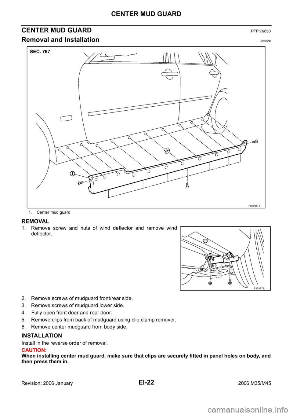
REMOVAL
1. Remove screw and nuts of wind deflector and remove wind
deflector.
2. Remove screws of mudguard front/rear side.
3. Remove screws of mudguard lower side.
4. Fully open front door and rear door.
5. Remove clips from back of mudguard using clip clamp remover.
6. Remove center mudguard from body side.
INSTALLATION
Install in the reverse order of removal.
CAUTION:
When installing center mud guard, make sure that clips are securely fitted in panel holes on body, and
then press them in.
1. Center mud guard
PIIB2941J
PIIB3973J
Page 3030 of 5621
ROOF SIDE MOLDING
EI-25
C
D
E
F
G
H
J
K
L
MA
B
EI
Revision: 2006 January2006 M35/M45
ROOF SIDE MOLDINGPFP:73854
Removal and InstallationNIS0024O
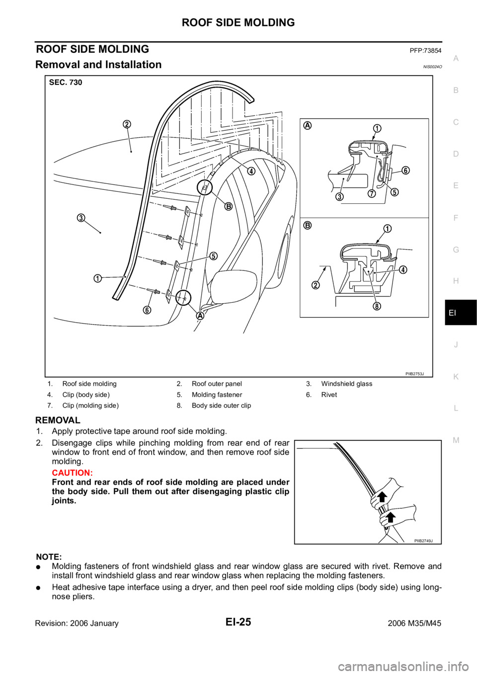
REMOVAL
1. Apply protective tape around roof side molding.
2. Disengage clips while pinching molding from rear end of rear
window to front end of front window, and then remove roof side
molding.
CAUTION:
Front and rear ends of roof side molding are placed under
the body side. Pull them out after disengaging plastic clip
joints.
NOTE:
Molding fasteners of front windshield glass and rear window glass are secured with rivet. Remove and
install front windshield glass and rear window glass when replacing the molding fasteners.
Heat adhesive tape interface using a dryer, and then peel roof side molding clips (body side) using long-
nose pliers.
1. Roof side molding 2. Roof outer panel 3. Windshield glass
4. Clip (body side) 5. Molding fastener 6. Rivet
7. Clip (molding side) 8. Body side outer clip
PIIB2753J
PIIB2749J
Page 3032 of 5621
DOOR SASH MOLDING
EI-27
C
D
E
F
G
H
J
K
L
MA
B
EI
Revision: 2006 January2006 M35/M45
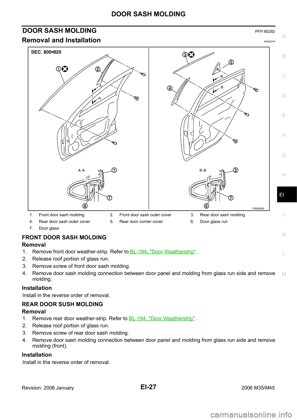
DOOR SASH MOLDINGPFP:80282
Removal and InstallationNIS0024P
FRONT DOOR SASH MOLDING
Removal
1. Remove front door weather-strip. Refer to BL-194, "Door Weatherstrip" .
2. Release roof portion of glass run.
3. Remove screw of front door sash molding.
4. Remove door sash molding connection between door panel and molding from glass run side and remove
molding.
Installation
Install in the reverse order of removal.
REAR DOOR SUSH MOLDING
Removal
1. Remove rear door weather-strip. Refer to BL-194, "Door Weatherstrip" .
2. Release roof portion of glass run.
3. Remove screw of rear door sash molding.
4. Remove door sash molding connection between door panel and molding from glass run side and remove
molding (front).
Installation
Install in the reverse order of removal.
1. Front door sash molding 2. Front door sash outer cover 3. Rear door sash molding
4. Rear door sash outer cover 5. Rear door corner cover 6. Door glass run
7. Door glass
PIIB5694E
Page 3037 of 5621
EI-32
DOOR PARTING SEAL
Revision: 2006 January2006 M35/M45
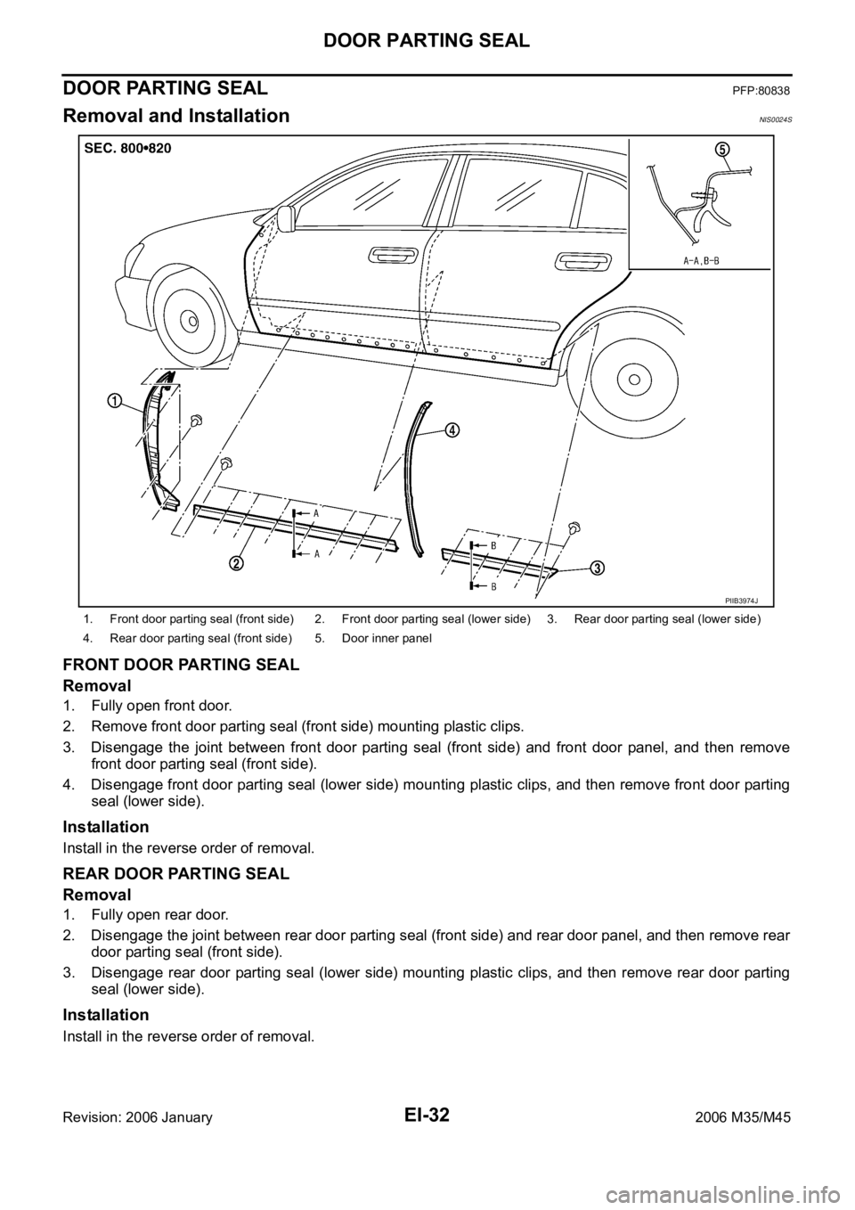
DOOR PARTING SEALPFP:80838
Removal and InstallationNIS0024S
FRONT DOOR PARTING SEAL
Removal
1. Fully open front door.
2. Remove front door parting seal (front side) mounting plastic clips.
3. Disengage the joint between front door parting seal (front side) and front door panel, and then remove
front door parting seal (front side).
4. Disengage front door parting seal (lower side) mounting plastic clips, and then remove front door parting
seal (lower side).
Installation
Install in the reverse order of removal.
REAR DOOR PARTING SEAL
Removal
1. Fully open rear door.
2. Disengage the joint between rear door parting seal (front side) and rear door panel, and then remove rear
door parting seal (front side).
3. Disengage rear door parting seal (lower side) mounting plastic clips, and then remove rear door parting
seal (lower side).
Installation
Install in the reverse order of removal.
1. Front door parting seal (front side) 2. Front door parting seal (lower side) 3. Rear door parting seal (lower side)
4. Rear door parting seal (front side) 5. Door inner panel
PIIB3974J
Page 3040 of 5621
DOOR FINISHER
EI-35
C
D
E
F
G
H
J
K
L
MA
B
EI
Revision: 2006 January2006 M35/M45
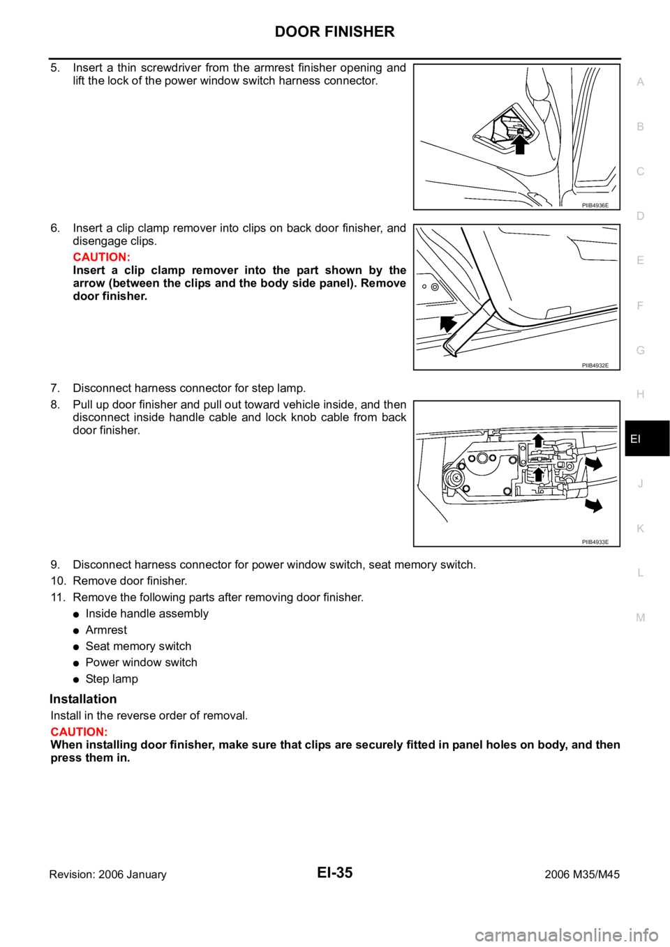
5. Insert a thin screwdriver from the armrest finisher opening and
lift the lock of the power window switch harness connector.
6. Insert a clip clamp remover into clips on back door finisher, and
disengage clips.
CAUTION:
Insert a clip clamp remover into the part shown by the
arrow (between the clips and the body side panel). Remove
door finisher.
7. Disconnect harness connector for step lamp.
8. Pull up door finisher and pull out toward vehicle inside, and then
disconnect inside handle cable and lock knob cable from back
door finisher.
9. Disconnect harness connector for power window switch, seat memory switch.
10. Remove door finisher.
11. Remove the following parts after removing door finisher.
Inside handle assembly
Armrest
Seat memory switch
Power window switch
St e p l am p
Installation
Install in the reverse order of removal.
CAUTION:
When installing door finisher, make sure that clips are securely fitted in panel holes on body, and then
press them in.
PIIB4936E
PIIB4932E
PIIB4933E
Page 3046 of 5621
BODY SIDE TRIM
EI-41
C
D
E
F
G
H
J
K
L
MA
B
EI
Revision: 2006 January2006 M35/M45
REAR WHEEL HOUSE GARNISH
Removal
1. Remove rear seat cushion and rear seatback. Refer to SE-176, "Removal and Installation" .
2. Remove rear body side welt.
3. Remove clip of rear wheel house garnish.
4. Remove rear wheel house garnish.
Installation
Install in the reverse order of removal.
NOTE:
To install, check if all clips are matched over holes of panel on vehicle, then push on.
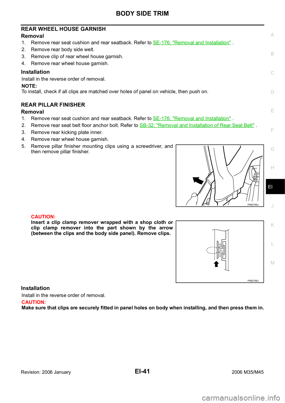
REAR PILLAR FINISHER
Removal
1. Remove rear seat cushion and rear seatback. Refer to SE-176, "Removal and Installation" .
2. Remove rear seat belt floor anchor bolt. Refer to SB-32, "
Removal and Installation of Rear Seat Belt" .
3. Remove rear kicking plate inner.
4. Remove rear wheel house garnish.
5. Remove pillar finisher mounting clips using a screwdriver, and
then remove pillar finisher.
CAUTION:
Insert a clip clamp remover wrapped with a shop cloth or
clip clamp remover into the part shown by the arrow
(between the clips and the body side panel). Remove clips.
Installation
Install in the reverse order of removal.
CAUTION:
Make sure that clips are securely fitted in panel holes on body when installing, and then press them in.
PIIB2769J
PIIB2768J