IDX INFINITI QX4 2001 Factory Service Manual
[x] Cancel search | Manufacturer: INFINITI, Model Year: 2001, Model line: QX4, Model: INFINITI QX4 2001Pages: 2395, PDF Size: 43.2 MB
Page 2144 of 2395

ªAIR BAGº warning lamp operation Ð User mode Ð SRS condition Reference item
MRS095A
No malfunction is
detected.
No further action is neces-
sary.Ð
MRS096A
The system is malfunction-
ing and needs to be
repaired as indicated.Go to DIAGNOSTIC PRO-
CEDURE 6 (RS-48).
MRS097A
Air bag is deployed.
Seat belt pre-tensioner is
deployed.Go to COLLISION DIAG-
NOSIS (RS-59).
Air bag fuse, diagnosis
sensor unit or harness is
malfunctioning and needs
to be repaired.Go to DIAGNOSTIC PRO-
CEDURE 9 RS-56).
MRS098A
One of the following has
occurred and needs to be
repaired.
IMeter fuse is blown.
IªAIR BAGº warning
lamp circuit has open or
short.
IDiagnosis sensor unit is
malfunctioning.Go to DIAGNOSTIC PRO-
CEDURE 10 (RS-58).
DIAGNOSTIC PROCEDURE 8 (CONTINUED FROM
DIAGNOSTIC PROCEDURE 6)
NBRS0046S03Inspecting SRS malfunctioning record
1 CONSIDER POSSIBILITY OF NOT ERASING SELF-DIAGNOSTIC RESULT AFTER REPAIRING
Is it the first time for maintenance of SRS?
YesorNo
Ye s©Go to DIAGNOSTIC PROCEDURE 5 (RS-44). (Further inspection cannot be performed
without CONSULT-II.)
No©Diagnosis results (previously stored in the memory) might not be erased after repair. Go
to DIAGNOSTIC PROCEDURE 7, step 5 (RS-53).
GI
MA
EM
LC
EC
FE
AT
TF
PD
AX
SU
BR
ST
BT
HA
SC
EL
IDX
SUPPLEMENTAL RESTRAINT SYSTEM (SRS)
Trouble Diagnoses without CONSULT-II (Cont'd)
RS-55
Page 2146 of 2395

4 CHECK DIAGNOSIS SENSOR UNIT
Connect CONSULT-II and touch ªSTARTº.
IIs ªAIR BAGº displayed on CONSULT-II?
SRS771
YesorNo
Ye s©GO TO 5.
No©Visually check the wiring harness connection of diagnosis sensor unit. If the harness
connection check result is OK, replace diagnosis sensor unit.
5 CHECK HARNESS CONNECTION
Is harness connection between warning lamp and diagnosis sensor unit OK?
OK or NG
OK©Replace diagnosis sensor unit.
NG©Connect ªAIR BAGº warning lamp and diagnosis sensor unit connector properly. If ªAIR
BAGº warning lamp still does not go off, replace harness.
GI
MA
EM
LC
EC
FE
AT
TF
PD
AX
SU
BR
ST
BT
HA
SC
EL
IDX
SUPPLEMENTAL RESTRAINT SYSTEM (SRS)
Trouble Diagnoses: ªAIR BAGº Warning Lamp Does Not Turn Off (Cont'd)
RS-57
Page 2148 of 2395

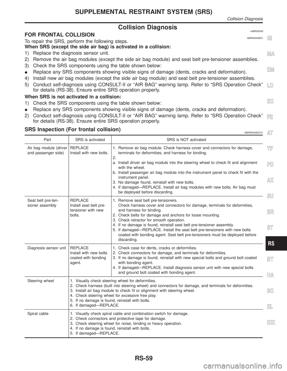
Collision Diagnosis=NBRS0049FOR FRONTAL COLLISIONNBRS0049S01To repair the SRS, perform the following steps.
When SRS (except the side air bag) is activated in a collision:
1) Replace the diagnosis sensor unit.
2) Remove the air bag modules (except the side air bag module) and seat belt pre-tensioner assemblies.
3) Check the SRS components using the table shown below:
IReplace any SRS components showing visible signs of damage (dents, cracks and deformation).
4) Install new air bag modules (except the side air bag module) and seat belt pre-tensioner assemblies.
5) Conduct self-diagnosis using CONSULT-II or ªAIR BAGº warning lamp. Refer to ªSRS Operation Checkº
for details (RS-38). Ensure entire SRS operation properly.
When SRS is not activated in a collision:
1) Check the SRS components using the table shown below:
IReplace any SRS components showing visible signs of damage (dents, cracks and deformation).
2) Conduct self-diagnosis using CONSULT-II or ªAIR BAGº warning lamp. Refer to ªSRS Operation Checkº
for details (RS-38). Ensure entire SRS operation properly.
SRS Inspection (For frontal collision)NBRS0049S0101
Part SRS is activated SRS is NOT activated
Air bag module (driver
and passenger side)REPLACE
Install with new bolts.1. Remove air bag module. Check harness cover and connectors for damage,
terminals for deformities, and harness for binding.
2.
a. Install driver air bag module into the steering wheel to check fit and alignment
with the wheel.
b. Install passenger air bag module into the instrument panel to check fit with the
instrument panel.
3. No damage found, reinstall with new bolts.
4. If damagedÐREPLACE. Install air bag modules with new bolts. Air bag must
be deployed before discarding.
Seat belt pre-ten-
sioner assemblyREPLACE
Install seat belt pre-
tensioner with new
bolts.1. Remove seat belt pre-tensioners.
Check harness cover and connectors for damage, terminals for deformities,
and harness for binding.
2. Check belts for damage and anchors for loose mounting.
3. Check retractor for smooth operation.
4. If no damage is found, reinstall seat belt pre-tensioner assembly.
5. If damagedÐREPLACE. Install the seat belt pre-tensioners with new bolts
coated with bonding agent. Seat belt pre-tensioners must be deployed before
discarding.
Diagnosis sensor unit REPLACE
Install with new bolts
coated with bonding
agent.1. Check case for dents, cracks or deformities.
2. Check connectors for damage, and terminals for deformities.
3. If no damage is found, reinstall with new special bolts and ground bolt coated
with bonding agent.
4. If damagedÐREPLACE. Install diagnosis sensor unit with new special bolts
and ground bolt coated with bonding agent.
Steering wheel 1. Visually check steering wheel for deformities.
2. Check harness (built into steering wheel) and connectors for damage, and terminals for deformities.
3. Install air bag module to check fit or alignment with steering wheel.
4. Check steering wheel for excessive free play.
5. If no damage is found, reinstall with bolts.
6. If damagedÐREPLACE.
Spiral cable 1. Visually check spiral cable and combination switch for damage.
2. Check connectors and protective tape for damage.
3. Check steering wheel for noise, binding or heavy operation.
4. If no damage is found, reinstall with bolts.
5. If damagedÐREPLACE.
GI
MA
EM
LC
EC
FE
AT
TF
PD
AX
SU
BR
ST
BT
HA
SC
EL
IDX
SUPPLEMENTAL RESTRAINT SYSTEM (SRS)
Collision Diagnosis
RS-59
Page 2150 of 2395

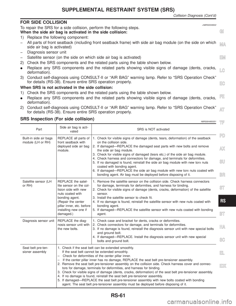
FOR SIDE COLLISION=NBRS0049S02To repair the SRS for a side collision, perform the following steps.
When the side air bag is activated in the side collision:
1) Replace the following component:
þ All parts of front seatback (including front seatback frame) with side air bag module (on the side on which
side air bag is activated)
þ Diagnosis sensor unit
þ Satellite sensor (on the side on which side air bag is activated)
2) Check the SRS components and the related parts using the table shown below.
IReplace any SRS components and the related parts showing visible signs of damage (dents, cracks,
deformation).
3) Conduct self-diagnosis using CONSULT-II or ªAIR BAGº warning lamp. Refer to ªSRS Operation Checkº
for details (RS-38). Ensure entire SRS operation properly.
When SRS is not activated in the side collision:
1) Check the SRS components and the related parts using the table shown below.
IReplace any SRS components and the related parts showing visible signs of damage (dents, cracks,
deformation).
2) Conduct self-diagnosis using CONSULT-II or ªAIR BAGº warning lamp. Refer to ªSRS Operation Checkº
for details (RS-38). Ensure entire SRS operation properly.
SRS Inspection (For side collision)NBRS0049S0201
PartSide air bag is acti-
vatedSRS is NOT activated
Built-in side air bags
module (LH or RH)REPLACE all parts of
front seatback with
deployed side air bag
module.1. Check for visible signs of damage (dents, tears, deformation) of the seatback
on the collision side.
2. If damagedÐREPLACE the damaged seat parts with new bolts and remove
the side air bag module.
3. Check for visible signs of damaged (tesrs etc.) of the side air bag module.
4. Check harness and connectors for damage, and terminals for deformities.
5. If no damaged is found, reinstall the side air bag module with new torx nuts
coated with bonding agent.
6. If damagedÐREPLACE the side air bag module with new torx nuts coated with
bonding agent. Air bag must be deployed before disposing of it.
Satellite sensor (LH
or RH)REPLACE the satel-
lite sensor on the col-
lision side with new
nuts coated with
bonding agent.
(Repair the center
pillar inner, etc. before
installing new one if
damaged.)1. Remove the satellite sensor on the collision side. Check harness connectors
for damage, terminals for deformities, and harness for binding.
2. Check for visible signs of damage (dents, cracks, deformation) of the satellite
sensor.
3. Install the satellite sensor to check fit.
4. If no damage is found, reinstall the satellite sensor with new nuts coated with
bonding agent.
5. If damagedÐREPLACE the satellite sensor with new nuts coated with bonding
agent.
Diagnosis sensor unit REPLACE the diag-
nosis sensor unit with
the new bolts.1. Check case and bracket for dents, cracks or deformities.
2. Check connectors for damage, and terminals for deformities.
3. If no damage is found, reinstall the diagnosis sensor unit with new special bolts
and ground bolt.
4. If damagedÐREPLACE. Install the diagnosis sensor unit with new special
bolts and ground bolt.
Seat belt pre-ten-
sioner assembly1. Check if the seat belt can be extended smoothly.
If the seat belt cannot be extended smoothly.
± Check for deformities of the center pillar inner.
± If the center pillar inner has no damage, REPLACE the seat belt pre-tensioner assembly.
2. Remove the seat belt pre-tensioner assembly on the collision side. Check harness cover and connec-
tors for damage, terminals for deformities, and harness for binding.
3. Check for visible signs of damage (dents, cracks, deformation) of the seat belt pre-tensioner assembly.
4. If no damage is found, reinstall the seat belt pre-tensioner assembly.
5. If damagedÐREPLACE the seat belt pre-tensioner assembly with new bolts coated with bonding
agent. The seat belt pre-tensioner assembly must be deployed before disposing of it.
GI
MA
EM
LC
EC
FE
AT
TF
PD
AX
SU
BR
ST
BT
HA
SC
EL
IDX
SUPPLEMENTAL RESTRAINT SYSTEM (SRS)
Collision Diagnosis (Cont'd)
RS-61
Page 2152 of 2395

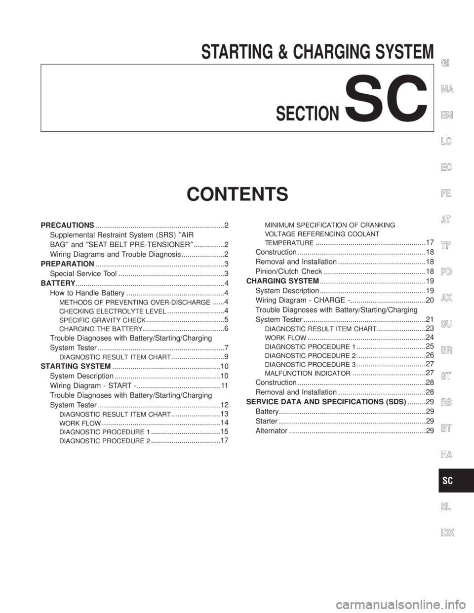
STARTING & CHARGING SYSTEM
SECTION
SC
CONTENTS
PRECAUTIONS...............................................................2
Supplemental Restraint System (SRS)²AIR
BAG²and²SEAT BELT PRE-TENSIONER²...............2
Wiring Diagrams and Trouble Diagnosis .....................2
PREPARATION...............................................................3
Special Service Tool ....................................................3
BATTERY.........................................................................4
How to Handle Battery ................................................4
METHODS OF PREVENTING OVER-DISCHARGE......4
CHECKING ELECTROLYTE LEVEL............................4
SPECIFIC GRAVITY CHECK......................................5
CHARGING THE BATTERY........................................6
Trouble Diagnoses with Battery/Starting/Charging
System Tester ..............................................................7
DIAGNOSTIC RESULT ITEM CHART..........................9
STARTING SYSTEM.....................................................10
System Description ....................................................10
Wiring Diagram - START -......................................... 11
Trouble Diagnoses with Battery/Starting/Charging
System Tester ............................................................12
DIAGNOSTIC RESULT ITEM CHART........................13
WORK FLOW..........................................................14
DIAGNOSTIC PROCEDURE 1..................................15
DIAGNOSTIC PROCEDURE 2..................................17
MINIMUM SPECIFICATION OF CRANKING
VOLTAGE REFERENCING COOLANT
TEMPERATURE
......................................................17
Construction ...............................................................18
Removal and Installation ...........................................18
Pinion/Clutch Check ..................................................18
CHARGING SYSTEM....................................................19
System Description ....................................................19
Wiring Diagram - CHARGE -.....................................20
Trouble Diagnoses with Battery/Starting/Charging
System Tester ............................................................21
DIAGNOSTIC RESULT ITEM CHART........................23
WORK FLOW..........................................................24
DIAGNOSTIC PROCEDURE 1..................................25
DIAGNOSTIC PROCEDURE 2..................................26
DIAGNOSTIC PROCEDURE 3..................................27
MALFUNCTION INDICATOR....................................27
Construction ...............................................................28
Removal and Installation ...........................................28
SERVICE DATA AND SPECIFICATIONS (SDS).........29
Battery........................................................................29
Starter ........................................................................29
Alternator ...................................................................29
GI
MA
EM
LC
EC
FE
AT
TF
PD
AX
SU
BR
ST
RS
BT
HA
EL
IDX
Page 2154 of 2395

Special Service ToolNBSC0017
Tool number
Tool nameDescription
J-44373 Model 620
Battery/Starting/Charging
system tester
SEL403X
GI
MA
EM
LC
EC
FE
AT
TF
PD
AX
SU
BR
ST
RS
BT
HA
EL
IDX
PREPARATION
Special Service Tool
SC-3
Page 2156 of 2395

MEL043F
IRemove the cell plug using a suitable tool.
IAdd distilled water up to the MAX level.
SEL709E
SulphationNBSC0003S0201A battery will be completely discharged if it is left unattended
for a long time and the specific gravity will become less than
1.100. This may result in sulphation on the cell plates.
To determine if a battery has been ªsulphatedº, note its volt-
age and current when charging it. As shown in the figure, less
current and higher voltage are observed in the initial stage of
charging sulphated batteries.
A sulphated battery may sometimes be brought back into ser-
vice by means of a long, slow charge, 12 hours or more, fol-
lowed by a battery capacity test.
MEL042FA
SPECIFIC GRAVITY CHECKNBSC0003S031. Read hydrometer and thermometer indications at eye level.
2. Use the chart below to correct your hydrometer reading
according to electrolyte temperature.
Hydrometer Temperature CorrectionNBSC0003S0301
Battery electrolyte temperature ÉC (ÉF) Add to specific gravity reading
71 (160) 0.032
66 (150) 0.028
60 (140) 0.024
54 (130) 0.020
49 (120) 0.016
43 (110) 0.012
38 (100) 0.008
32 (90) 0.004
27 (80) 0
21 (70) þ0.004
16 (60) þ0.008
10 (50) þ0.012
GI
MA
EM
LC
EC
FE
AT
TF
PD
AX
SU
BR
ST
RS
BT
HA
EL
IDX
BATTERY
How to Handle Battery (Cont'd)
SC-5
Page 2158 of 2395

Trouble Diagnoses with
Battery/Starting/Charging System Tester
NBSC0018CAUTION:
When working with batteries, always wear appropriate eye
protection.
NOTE:
ITo ensure a complete and thorough diagnosis, the battery,
starter and alternator test segments must be done as a set
from start to finish.
IIf battery surface charge is detected while testing, the tester
will prompt you to turn on the headlights to remove the surface
charge.
IIf necessary, the tester will prompt you to determine if the bat-
tery temperature is above or below 0ÉC (32ÉF). Choose the
appropriate selection by pressing the up or down arrow button,
then press ªENTERº to make the selection.
SEL404X
1. Turn off all loads on the vehicle electrical system. Clean or
repair as necessary.
2. Visually inspect the battery, battery terminals and cable ends
with ignition switch in ªOFFº position.
NOTE:
The contact surface between the battery terminals, cable ends and
tester leads must be clean for a valid test. A poor connection will
prevent testing and a ªCHECK CONNECTIONº message will
appear during the test procedures. If this occurs, clean the battery
post and terminals, reconnect them and restart the test.
3. Connect the red tester lead clamp to the positive battery
terminal, and the black to the negative terminal.
SEL405X
4. The tester will turn on automatically. Using the arrow keys,
select ªIN VEHICLEº on the tester and then press the ªENTERº
key.
GI
MA
EM
LC
EC
FE
AT
TF
PD
AX
SU
BR
ST
RS
BT
HA
EL
IDX
BATTERY
Trouble Diagnoses with Battery/Starting/Charging System Tester
SC-7
Page 2160 of 2395

DIAGNOSTIC RESULT ITEM CHARTNBSC0018S01
Diagnostic item Service procedure
GOOD BATTERY Battery is OK, go to ªTrouble Diagnosesº, ªSTARTING SYSTEMº. Refer to SC-12.
REPLACE BATTERYReplace battery.
Before replacing battery, clean the battery cable clamps and battery posts. Perform bat-
tery test again with Battery/Starting/Charging system tester. If second test result is
ªReplace Batteryº, then do so. Perform battery test again to confirm repair.
BAD CELL-REPLACEReplace the battery. Perform battery test again with Battery/Starting/Charging system
tester to confirm repair.
GOOD-RECHARGEPerform the slow battery charging procedure. (Initial rate of charge is 10A for 12 hours.)
Perform battery test again with Battery/Starting/Charging system tester.
CHARGE & RETESTPerform the slow battery charging. (Initial rate of charge is 10A for 12 hours.)
Perform battery test again with Battery/Starting/Charging system tester to confirm repair.
NOTE:
If the tester asks the user ªBEFORE CHARGE/AFTER CHARGEº, select ªAFTER
CHARGEº.GI
MA
EM
LC
EC
FE
AT
TF
PD
AX
SU
BR
ST
RS
BT
HA
EL
IDX
BATTERY
Trouble Diagnoses with Battery/Starting/Charging System Tester (Cont'd)
SC-9
Page 2162 of 2395

Wiring Diagram Ð START ÐNBSC0005
MEL652L
GI
MA
EM
LC
EC
FE
AT
TF
PD
AX
SU
BR
ST
RS
BT
HA
EL
IDX
STARTING SYSTEM
Wiring Diagram Ð START Ð
SC-11