IDX INFINITI QX4 2001 Factory Service Manual
[x] Cancel search | Manufacturer: INFINITI, Model Year: 2001, Model line: QX4, Model: INFINITI QX4 2001Pages: 2395, PDF Size: 43.2 MB
Page 2064 of 2395

Tool number
(Kent-Moore No.)
Tool nameDescription
ST33190000
(J25523)
Differential side bearing
drift
NT085
Installing side bearing inner cone
a: 52 mm (2.05 in) dia.
b: 45.5 mm (1.791 in) dia.
c: 34 mm (1.34 in) dia.
ST33081000
(Ð)
Side bearing puller
adapter
NT431
Installing side bearing inner cone
a: 43 mm (1.69 in) dia.
b: 33.5 mm (1.319 in) dia.
ST30611000
(J25742-1)
Drift
NT090
Installing pinion rear bearing outer race
(Use with ST30621000 or ST30613000)
ST30621000
(J25742-5)
Drift
NT073
Installing pinion rear bearing outer race
a: 79 mm (3.11 in) dia.
b: 59 mm (2.32 in) dia.
ST30613000
(J25742-3)
Drift
NT073
Installing pinion front bearing outer race
(Use with ST30611000)
a: 72 mm (2.83 in) dia.
b: 48 mm (1.89 in) dia.
KV381025S0
(Ð)
Oil seal fitting tool
1 ST30720000
(J25405)
Drift bar
2 KV38102510
(Ð)
Drift
NT525
Installing front oil seal
a: 77 mm (3.03 in) dia.
b: 55 mm (2.17 in) dia.
c: 71 mm (2.80 in) dia.
d: 65 mm (2.56 in) dia.
(J34309)
Differential shim selec-
tor
NT134
Adjusting bearing pre-load and gear height
GI
MA
EM
LC
EC
FE
AT
TF
AX
SU
BR
ST
RS
BT
HA
SC
EL
IDX
REAR FINAL DRIVEH233B
Preparation (Cont'd)
PD-39
Page 2066 of 2395

SPD738
4. Remove front oil seal.
SPD739
5. Apply multi-purpose grease to cavity at sealing lips of oil seal.
Press front oil seal into carrier.
Tool number:
KV38100500 (J25273)
6. Install companion flange and drive pinion nut.
7. Install rear propeller shaft.
GI
MA
EM
LC
EC
FE
AT
TF
AX
SU
BR
ST
RS
BT
HA
SC
EL
IDX
REAR FINAL DRIVEH233B
On-vehicle Service (Cont'd)
PD-41
Page 2068 of 2395

Removal and InstallationNBPD0032REMOVALNBPD0032S01IRemove rear of propeller shaft.
Plug front end of transfer.
IRemove axle shaft.
Refer to AX-19, ªRemovalº.
IRemove rear final drive mounting bolts.
CAUTION:
Be careful not to damage spline, sleeve yoke and front oil seal
when removing propeller shaft.
SPD123
INSTALLATIONNBPD0032S02IFill final drive with recommended gear oil.
SPD767
IPay attention to the direction of gasket.
SPD149
DisassemblyNBPD0033PRE-INSPECTIONNBPD0033S01Before disassembling final drive, perform the following inspection.
ITotal preload
a) Turn drive pinion in both directions several times to seat bear-
ing rollers correctly.
b) Check total preload with Tool.
Tool number: ST3127S000 (J25765-A)
Total preload:
1.2 - 2.0 N´m (12 - 20 kg-cm, 10 - 17 in-lb)
SPD246
IRing gear to drive pinion backlash
Check backlash of ring gear with a dial indicator at several
points.
Ring gear-to-drive pinion backlash:
0.13 - 0.18 mm (0.0051 - 0.0071 in)
GI
MA
EM
LC
EC
FE
AT
TF
AX
SU
BR
ST
RS
BT
HA
SC
EL
IDX
REAR FINAL DRIVEH233B
Removal and Installation
PD-43
Page 2070 of 2395

SPD684
4. Remove side bearing adjuster with Tool.
Tool number: ST32580000 (J34312)
SPD685
5. Remove differential case assembly with a pry bar.
SPD011
Be careful to keep the side bearing outer races together with
their respective inner cones Ð do not mix them up.
SPD480A
6. Remove drive pinion nut with Tool.
Tool number: KV38108300 (J44195)
7. Remove companion flange with puller.
SPD687
8. Take out drive pinion together with pinion rear bearing inner
cone, drive pinion bearing spacer and pinion bearing adjusting
shim.
GI
MA
EM
LC
EC
FE
AT
TF
AX
SU
BR
ST
RS
BT
HA
SC
EL
IDX
REAR FINAL DRIVEH233B
Disassembly (Cont'd)
PD-45
Page 2072 of 2395

SPD025
4. Drive out pinion mate shaft lock pin, with punch from ring gear
side.
Lock pin is calked at pin hole mouth on differential case.
InspectionNBPD0034RING GEAR AND DRIVE PINIONNBPD0034S01Check gear teeth for scoring, cracking or chipping.
If any damaged part is evident, replace ring gear and drive pinion
as a set (hypoid gear set).
SPD530-A
DIFFERENTIAL CASE ASSEMBLYNBPD0034S02Check mating surfaces of differential case, side gears, pinion mate
gears, pinion mate shaft, and thrust washers.
SPD715
BEARINGNBPD0034S031. Thoroughly clean bearing.
2. Check bearings for wear, scratches, pitting or flaking.
Check tapered roller bearing for smooth rotation. If damaged,
replace outer race and inner cone as a set.
SPD415
Limited Slip Differential
PREPARATION FOR DISASSEMBLYNBPD0035Checking Differential TorqueNBPD0035S01Measure differential torque with Tool.
If it is not within the specifications, inspect components of limited
slip differential.
Differential torque:
88 - 108 N´m (9 - 11 kg-m, 65 - 80 ft-lb)
Tool number: A KV38105210 ( Ð )
Tool number: B KV38105220 ( Ð )
GI
MA
EM
LC
EC
FE
AT
TF
AX
SU
BR
ST
RS
BT
HA
SC
EL
IDX
REAR FINAL DRIVEH233B
Disassembly (Cont'd)
PD-47
Page 2074 of 2395

SPD359A
INSPECTIONNBPD0037Contact SurfacesNBPD0037S011. Clean the disassembled parts in suitable solvent and blow dry
with compressed air.
2. If following surfaces are found with burrs or scratches, smooth
with oil stone.
1Differential case B
2Differential case A
3Side gear
4Pinion mate gear
5Pinion mate shaft
6Friction plate guide
Disc and PlateNBPD0037S021. Clean the discs and plates in suitable solvent and blow dry with
compressed air.
2. Inspect discs and plates for wear, nicks and burrs.
SPD279
3. To test if friction disc or plate is not distorted, place it on a sur-
face plate and rotate it by hand with indicating finger of dial
gauge resting against disc or plate surface.
Allowable warpage:
0.08 mm (0.0031 in)
If it exceeds limits, replace with a new plate to eliminate pos-
sibility of clutch slippage or sticking.
GI
MA
EM
LC
EC
FE
AT
TF
AX
SU
BR
ST
RS
BT
HA
SC
EL
IDX
REAR FINAL DRIVEH233B
Limited Slip Differential (Cont'd)
PD-49
Page 2076 of 2395

SPD418
3. Measure values of ªCº.
a. Attach a dial indicator to the base plate.
b. Place differential case B on the base plate, and install a mas-
ter gauge on case B.
Then adjust the dial indicator scale to zero with its tip on
the master gauge.
SPD419
c. Install pinion mate gears, side gears and pinion mate shaft in
differential case B.
d. Set dial indicator's tip on the side gear, and read the indication.
Example:
E = A þ D = A þ (B + C) = 0.05 to 0.15 mm
A = 49.52 mm
B = 19.45 mm
C = 29.7 mm
D=B+C
49.15 (D) = 19.45 (B) + 29.7 (C)
E =Aþ D
0.37 (E) = 49.52 (A) þ 49.15 (D)
From the above equation, end play of 0.37 mm exceeds the speci-
fied range of 0.05 to 0.15 mm.
Select suitable discs and plates to adjust correctly.
SPD421
ASSEMBLYNBPD0039Prior to assembling discs and plates, properly lubricate them by
dipping them in limited slip differential oil.
1. Alternately position specified number of friction plates and fric-
tion discs on rear of side gear.
Always position a friction plate first on rear of side gear.
SPD384A
2. Install spring plate.
GI
MA
EM
LC
EC
FE
AT
TF
AX
SU
BR
ST
RS
BT
HA
SC
EL
IDX
REAR FINAL DRIVEH233B
Limited Slip Differential (Cont'd)
PD-51
Page 2078 of 2395

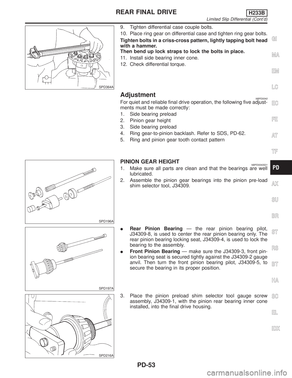
SPD364A
9. Tighten differential case couple bolts.
10. Place ring gear on differential case and tighten ring gear bolts.
Tighten bolts in a criss-cross pattern, lightly tapping bolt head
with a hammer.
Then bend up lock straps to lock the bolts in place.
11. Install side bearing inner cone.
12. Check differential torque.
AdjustmentNBPD0040For quiet and reliable final drive operation, the following five adjust-
ments must be made correctly:
1. Side bearing preload
2. Pinion gear height
3. Side bearing preload
4. Ring gear-to-pinion backlash. Refer to SDS, PD-62.
5. Ring and pinion gear tooth contact pattern
SPD196A
PINION GEAR HEIGHTNBPD0040S011. Make sure all parts are clean and that the bearings are well
lubricated.
2. Assemble the pinion gear bearings into the pinion pre-load
shim selector tool, J34309.
SPD197A
IRear Pinion BearingÐ the rear pinion bearing pilot,
J34309-8, is used to center the rear pinion bearing only. The
rear pinion bearing locking seat, J34309-4, is used to lock the
bearing to the assembly.
IFront Pinion BearingÐ make sure the J34309-3, front pin-
ion bearing seat is secured tightly against the J34309-2 gauge
anvil. Then turn the front pinion bearing pilot, J34309-5, to
secure the bearing in its proper position.
SPD216A
3. Place the pinion preload shim selector tool gauge screw
assembly, J34309-1, with the pinion rear bearing inner cone
installed, into the final drive housing.
GI
MA
EM
LC
EC
FE
AT
TF
AX
SU
BR
ST
RS
BT
HA
SC
EL
IDX
REAR FINAL DRIVEH233B
Limited Slip Differential (Cont'd)
PD-53
Page 2080 of 2395

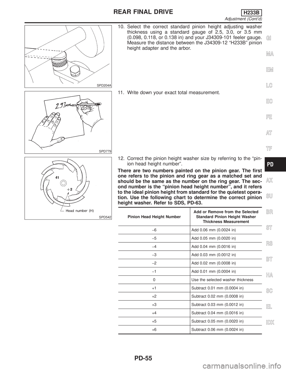
SPD204A
10. Select the correct standard pinion height adjusting washer
thickness using a standard gauge of 2.5, 3.0, or 3.5 mm
(0.098, 0.118, or 0.138 in) and your J34309-101 feeler gauge.
Measure the distance between the J34309-12 ªH233Bº pinion
height adapter and the arbor.
SPD779
11. Write down your exact total measurement.
SPD542
12. Correct the pinion height washer size by referring to the ªpin-
ion head height numberº.
There are two numbers painted on the pinion gear. The first
one refers to the pinion and ring gear as a matched set and
should be the same as the number on the ring gear. The sec-
ond number is the ªpinion head height numberº, and it refers
to the ideal pinion height from standard for the quietest opera-
tion. Use the following chart to determine the correct pinion
height washer. Refer to SDS, PD-63.
Pinion Head Height NumberAdd or Remove from the Selected
Standard Pinion Height Washer
Thickness Measurement
þ6 Add 0.06 mm (0.0024 in)
þ5 Add 0.05 mm (0.0020 in)
þ4 Add 0.04 mm (0.0016 in)
þ3 Add 0.03 mm (0.0012 in)
þ2 Add 0.02 mm (0.0008 in)
þ1 Add 0.01 mm (0.0004 in)
0 Use the selected washer thickness
+1 Subtract 0.01 mm (0.0004 in)
+2 Subtract 0.02 mm (0.0008 in)
+3 Subtract 0.03 mm (0.0012 in)
+4 Subtract 0.04 mm (0.0016 in)
+5 Subtract 0.05 mm (0.0020 in)
+6 Subtract 0.06 mm (0.0024 in)
GI
MA
EM
LC
EC
FE
AT
TF
AX
SU
BR
ST
RS
BT
HA
SC
EL
IDX
REAR FINAL DRIVEH233B
Adjustment (Cont'd)
PD-55
Page 2082 of 2395

SPD007-B
SPD552
AssemblyNBPD0041DIFFERENTIAL CASENBPD0041S011. Install side gears, pinion mate gears and thrust washers into
differential case.
SPD258
2. Fit pinion mate shaft to differential case so that it meets lock
pin holes.
3. Adjust backlash between side gear and pinion mate gear by
selecting side gear thrust washer.
Refer to SDS, PD-62.
Backlash between side gear and pinion mate gear
(Clearance between side gear thrust washer and differ-
ential case):
0.10 - 0.20 mm (0.0039 - 0.0079 in)
SPD030
4. Install pinion mate shaft lock pin with a punch.
Make sure lock pin is flush with case.
GI
MA
EM
LC
EC
FE
AT
TF
AX
SU
BR
ST
RS
BT
HA
SC
EL
IDX
REAR FINAL DRIVEH233B
Adjustment (Cont'd)
PD-57