IDX INFINITI QX4 2001 Factory Service Manual
[x] Cancel search | Manufacturer: INFINITI, Model Year: 2001, Model line: QX4, Model: INFINITI QX4 2001Pages: 2395, PDF Size: 43.2 MB
Page 2104 of 2395

Diagnosis Sensor Unit
REMOVAL AND INSTALLATIONNBRS0012CAUTION:
IBefore servicing SRS, turn the ignition switch off, discon-
nect both battery cables and wait for at least 3 minutes.
IThe special bolts are coated with bonding agent while the
other bolt is for ground. Do not use old bolts after
removal; replace with new ones.
ICheck diagnosis sensor unit for proper installation.
ICheck diagnosis sensor unit to ensure it is free of
deformities, dents, cracks or rust. If they show any visible
signs of damage, replace them with new ones.
ICheck diagnosis sensor unit brackets to ensure they are
free of deformities or rust.
IReplace diagnosis sensor unit if it has been dropped or
sustained an impact.
IAfter replacement of diagnosis sensor unit, perform self-
diagnosis for SRS. Refer to ªSRS Operation Checkº for
details (RS-38).
SRS636-A
1. Disconnect connectors for driver and passenger air bag mod-
ules and seat belt pre-tensioner.
2. Remove console box. Refer to BT-21, ªINSTRUMENT PANEL
ASSEMBLYº.
3. Disconnect diagnosis sensor unit connector.
4. Remove ground bolt and also remove special bolts using the
TAMPER RESISTANT TORX (Size T50), from diagnosis sen-
sor unit.
Then remove the diagnosis sensor unit.
NOTE:
ITo install, reverse the removal procedure sequence.
SRS651-C
Seat Belt Pre-tensioner
REMOVAL AND INSTALLATIONNBRS0034CAUTION:
IBefore servicing SRS, turn the ignition switch off, discon-
nect both battery cables and wait at least 3 minutes.
ICheck seat belt pre-tensioner with load limiter for proper
installation.
IAfter replacement of seat belt pre-tensioner, check SRS
function and perform self-diagnosis for SRS. Refer to
ªSRS Operation Checkº for details. (RS-38)
IDo not attempt to disassemble seat belt pre-tensioner with
load limiter.
IReplace seat belt pre-tensioner if it has been dropped or
sustained an impact.
IDo not expose seat belt pre-tensioner to temperatures
exceeding 80ÉC (176ÉF).
For removal of seat belt pre-tensioner, refer to ªFront Seat Beltº for
details. (RS-4)
NOTE:
ITo install, reverse the removal procedure sequence.
GI
MA
EM
LC
EC
FE
AT
TF
PD
AX
SU
BR
ST
BT
HA
SC
EL
IDX
SUPPLEMENTAL RESTRAINT SYSTEM (SRS)
Diagnosis Sensor Unit
RS-15
Page 2106 of 2395

Driver Air Bag Module and Spiral Cable
REMOVAL AND INSTALLATIONNBRS0013
SRS782-A
SBF811E
REMOVALNBRS0014CAUTION:
IBefore servicing SRS, turn the ignition switch off, discon-
nect both battery cables and wait at least 3 minutes.
IAlways work from the side of air bag module.
1. Remove lower lid from steering wheel, and disconnect air bag
module connector.
SBF812E
2. Remove side lids, ASCD steering switch and Audio steering
switch (or TEL switch). Using the TAMPER RESISTANT TORX
(Size T50), remove left and right special bolts. Air bag module
can then be removed.
SRS161
CAUTION:
IAlways place air bag module with pad side facing upward.
IDo not attempt to disassemble air bag module.
IThe special bolts are coated with bonding agent. Do not
use old bolts after removal; replace with new ones.
IDo not insert any foreign objects (screwdriver, etc.) into
air bag module connector.
GI
MA
EM
LC
EC
FE
AT
TF
PD
AX
SU
BR
ST
BT
HA
SC
EL
IDX
SUPPLEMENTAL RESTRAINT SYSTEM (SRS)
Driver Air Bag Module and Spiral Cable
RS-17
Page 2108 of 2395

SBF812EH
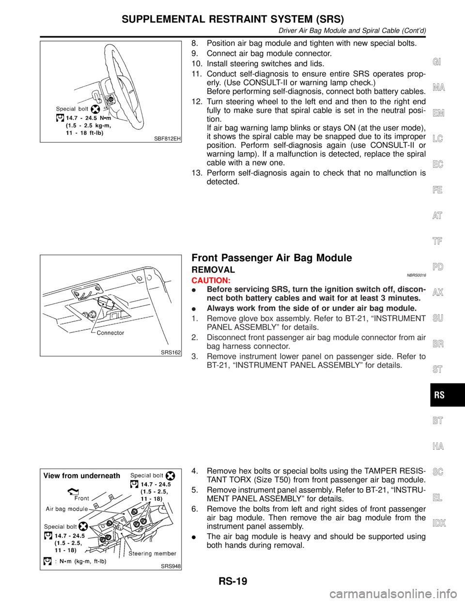
8. Position air bag module and tighten with new special bolts.
9. Connect air bag module connector.
10. Install steering switches and lids.
11. Conduct self-diagnosis to ensure entire SRS operates prop-
erly. (Use CONSULT-II or warning lamp check.)
Before performing self-diagnosis, connect both battery cables.
12. Turn steering wheel to the left end and then to the right end
fully to make sure that spiral cable is set in the neutral posi-
tion.
If air bag warning lamp blinks or stays ON (at the user mode),
it shows the spiral cable may be snapped due to its improper
position. Perform self-diagnosis again (use CONSULT-II or
warning lamp). If a malfunction is detected, replace the spiral
cable with a new one.
13. Perform self-diagnosis again to check that no malfunction is
detected.
SRS162
Front Passenger Air Bag Module
REMOVALNBRS0016CAUTION:
IBefore servicing SRS, turn the ignition switch off, discon-
nect both battery cables and wait for at least 3 minutes.
IAlways work from the side of or under air bag module.
1. Remove glove box assembly. Refer to BT-21, ªINSTRUMENT
PANEL ASSEMBLYº for details.
2. Disconnect front passenger air bag module connector from air
bag harness connector.
3. Remove instrument lower panel on passenger side. Refer to
BT-21, ªINSTRUMENT PANEL ASSEMBLYº for details.
SRS948
4. Remove hex bolts or special bolts using the TAMPER RESIS-
TANT TORX (Size T50) from front passenger air bag module.
5. Remove instrument panel assembly. Refer to BT-21, ªINSTRU-
MENT PANEL ASSEMBLYº for details.
6. Remove the bolts from left and right sides of front passenger
air bag module. Then remove the air bag module from the
instrument panel assembly.
IThe air bag module is heavy and should be supported using
both hands during removal.
GI
MA
EM
LC
EC
FE
AT
TF
PD
AX
SU
BR
ST
BT
HA
SC
EL
IDX
SUPPLEMENTAL RESTRAINT SYSTEM (SRS)
Driver Air Bag Module and Spiral Cable (Cont'd)
RS-19
Page 2110 of 2395

SRS162
4. Install instrument lower panel on passenger side.
5. Connect air bag module connector to air bag harness connec-
tor.
6. Install glove box assembly.
7. Connect both battery cables.
8. Conduct self-diagnosis to ensure entire SRS operates prop-
erly. (Use CONSULT-II or warning lamp check.)
SRS682
Side Air Bag Module
REMOVALNBRS0036CAUTION:
IBefore servicing SRS, turn the ignition switch OFF, dis-
connect both battery cables and wait at least 3 minutes.
IAlways work from the rear of the air bag module.
1. Remove seatback board.
IWhen using a clip removal tool to remove the seatback
board, take care not to damage the air bag harness.
2. Disconnect side air bag module connector by sliding tab.
SRS683
3. Pull up the seatback trim.
4. Remove the nuts securing the inner cloth with seatback frame.
Then pull up the inner cloth.
5. Remove seatback trim. Refer to BT-41, ªFRONT SEATº for
details.
SRS684
6. Remove the torx nuts coated with bonding agent from the side
air bag module.
7. Remove side air bag connector. Side air bag module can then
be removed.
SRS623
CAUTION:
IAlways place the air bag module stading with the stud bolt
side setting bottom.
IDo not attempt to disassemble air bag module.
IThe torx nuts are coated with bonding agent. Do not use
old nuts after removal; replace with new coated nuts.
IDo not insert any foreign objects (screwdriver, etc.) into
air bag module connector.
GI
MA
EM
LC
EC
FE
AT
TF
PD
AX
SU
BR
ST
BT
HA
SC
EL
IDX
SUPPLEMENTAL RESTRAINT SYSTEM (SRS)
Front Passenger Air Bag Module (Cont'd)
RS-21
Page 2112 of 2395

IWhen deploying the air bag module and seat belt pre-
tensioner, stand at least 5 m (16 ft) away from the deployment
component.
IWhen deploying air bag module and seat belt pre-tensioner, a
fairly loud noise is made, followed by smoke being released.
The smoke is not poisonous, however, be careful not to inhale
smoke since it irritates the throat and can cause choking.
IAlways activate one air bag module at a time.
IDue to heat, leave air bag module unattended for more than
30 minutes after deployment. Also leave seat belt pre-ten-
sioner unattended for move than 10 minutes after deployment.
IBe sure to wear gloves when handling a deployed air bag
module and seat belt pre-tensioner.
INever apply water to the deployed air bag module and seat
belt pre-tensioner.
IWash your hands clean after finishing work.
IPlace the vehicle outdoors with an open space of at least 6 m
(20 ft) on all sides when deploying air bag module and seat belt
pre-tensioner while mounted in vehicle.
IUse a voltmeter to make sure the vehicle battery is fully
charged.
IDo not dispose of the air bag module and seat belt pre-ten-
sioner un-deployed.
SRS019
CHECKING DEPLOYMENT TOOLNBRS0018S01Connecting to BatteryNBRS0018S0101CAUTION:
The battery must show voltage of 9.6V or more.
Remove the battery from the vehicle and place it on dry wood
blocks approximately 5 m (16 ft) away from the vehicle.
IWait 3 minutes after the vehicle battery is disconnected before
proceeding.
IConnect red clip of deployment tool to battery positive termi-
nal and black clip to negative terminal.
Make sure the polarity is correct. The right side lamp in the
tool, marked ªdeployment tool powerº, should glow with a
green light. If the right side lamp glows red, reverse the con-
nections to the battery.
GI
MA
EM
LC
EC
FE
AT
TF
PD
AX
SU
BR
ST
BT
HA
SC
EL
IDX
SUPPLEMENTAL RESTRAINT SYSTEM (SRS)
Disposal of Air Bag Module and Seat Belt Pre-tensioner (Cont'd)
RS-23
Page 2114 of 2395

SRS020-B
5. Connect red clip of deployment tool to battery positive termi-
nal and black clip to negative terminal.
6. The lamp on the right side of the tool, marked ªdeployment tool
powerº, should glow green, not red.
7. Press the button on the deployment tool. The left side lamp on
the tool, marked ªair bag connector voltageº, will illuminate and
the air bag module will deploy.
CAUTION:
When deploying the air bag module, stand at least 5 m (16 ft)
away from the air bag module.
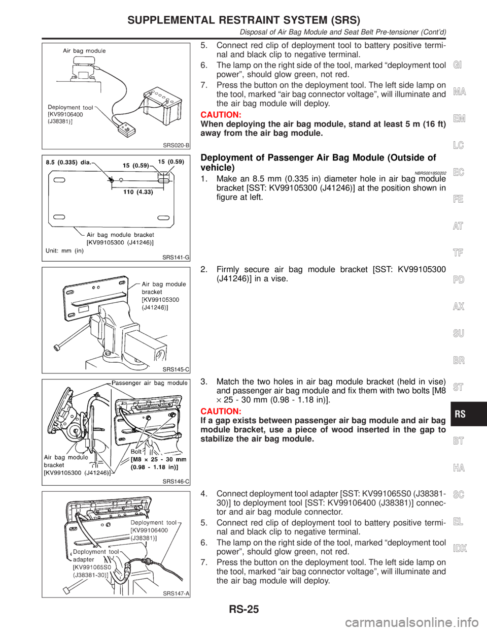
SRS141-G
Deployment of Passenger Air Bag Module (Outside of
vehicle)
NBRS0018S02021. Make an 8.5 mm (0.335 in) diameter hole in air bag module
bracket [SST: KV99105300 (J41246)] at the position shown in
figure at left.
SRS145-C
2. Firmly secure air bag module bracket [SST: KV99105300
(J41246)] in a vise.
SRS146-C
3. Match the two holes in air bag module bracket (held in vise)
and passenger air bag module and fix them with two bolts [M8
´25 - 30 mm (0.98 - 1.18 in)].
CAUTION:
If a gap exists between passenger air bag module and air bag
module bracket, use a piece of wood inserted in the gap to
stabilize the air bag module.
SRS147-A
4. Connect deployment tool adapter [SST: KV991065S0 (J38381-
30)] to deployment tool [SST: KV99106400 (J38381)] connec-
tor and air bag module connector.
5. Connect red clip of deployment tool to battery positive termi-
nal and black clip to negative terminal.
6. The lamp on the right side of the tool, marked ªdeployment tool
powerº, should glow green, not red.
7. Press the button on the deployment tool. The left side lamp on
the tool, marked ªair bag connector voltageº, will illuminate and
the air bag module will deploy.
GI
MA
EM
LC
EC
FE
AT
TF
PD
AX
SU
BR
ST
BT
HA
SC
EL
IDX
SUPPLEMENTAL RESTRAINT SYSTEM (SRS)
Disposal of Air Bag Module and Seat Belt Pre-tensioner (Cont'd)
RS-25
Page 2116 of 2395

SRS662
DEPLOYMENT PROCEDURES FOR SEAT BELT PRE-
TENSIONER (OUTSIDE OF VEHICLE)
NBRS0018S051. Firmly grip pre-tensioner in a vise and cut the webbing off.
SRS663
2. Connect deployment tool adapter [SST: KV99108200 (J38381-
50)] to deployment tool [SST: KV99106400 (J38381)] connec-
tor and seat belt pre-tensioner connector.
SRS242
3. Connect red clip of deployment tool to battery positive termi-
nal and black clip to negative terminal.
4. The lamp on the right side of the tool, marked ªdeployment tool
powerº, should glow green, not red.
5. Press the button on the deployment tool. The left side lamp on
the tool, marked ªseat belt pre-tensioner connector voltageº,
will illuminate and the seat belt pre-tensioner will deploy.
CAUTION:
When deploying the seat belt pre-tensioner, stand at least 5 m
(16 ft) away from the seat belt pre-tensioner.
DEPLOYMENT OF AIR BAG MODULE AND SEAT BELT
PRE-TENSIONER WHILE MOUNTED IN VEHICLE
NBRS0018S03When disposing of a vehicle, deploy air bag module and seat belt
pre-tensioners while they are mounted in vehicle.
CAUTION:
When deploying air bag module or seat belt pre-tensioner,
ensure vehicle is empty.
1. Disconnect both the vehicle battery cables and wait 3 minutes.
2. Disconnect air bag module and seat belt pre-tensioner connec-
tor.
3. Connect deployment tool [SST: KV99106400 (J38381)] to air
bag module or seat belt pre-tensioner.
For front passenger air bag module, attach deployment tool
adapter [SST: KV991065S0 (J38381-30)] to the tool connector.
For side air bag module (built-in type), attach deployment tool
adapter [SST: KV99109000 (J44230)]. For seat belt pre-
tensioner, attach deployment tool adapter [SST: KV99108200
(J38381-50)] to the tool connector.
GI
MA
EM
LC
EC
FE
AT
TF
PD
AX
SU
BR
ST
BT
HA
SC
EL
IDX
SUPPLEMENTAL RESTRAINT SYSTEM (SRS)
Disposal of Air Bag Module and Seat Belt Pre-tensioner (Cont'd)
RS-27
Page 2118 of 2395

Trouble Diagnoses Introduction=NBRS0040CAUTION:
IDo not use electrical test equipment on any circuit related to the SRS unless instructed to in this
Service Manual. Spiral cable and wiring harnesses covered with yellow insulation tape either just
before the harness connectors or for the complete harness are related to the SRS.
IDo not attempt to repair, splice or modify the SRS wiring harness. If the harness is damaged,
replace it with a new one.
IKeep ground portion clean.
DIAGNOSIS FUNCTIONNBRS0040S01The SRS self-diagnosis results can be read by using ªAIR BAGº warning lamp and/or CONSULT-II. The read-
ing of these results is accomplished using one of two modes Ð ªUser modeº and ªDiagnosis modeº.
The User mode is exclusively prepared for the customer (driver). This mode warns the driver of a system
malfunction through the operation of the ªAIR BAGº warning lamp.
The Diagnosis mode allows the technician to locate and inspect the malfunctioning part.
The mode applications for the ªAIR BAGº warning lamp and CONSULT-II are as follows:
User mode Diagnosis mode Display type
ªAIR BAGº warning lamp X X ON-OFF operation
CONSULT-II Ð X Monitoring
NOTE:
Seat belt pre-tensioner malfunction is indicated by ªAIR BAGº warning lamp.
DIAGNOSIS MODE FOR CONSULT-IINBRS0040S02IªSELF-DIAG [CURRENT]º
A current Self-diagnosis result (also indicated by the number of warning lamp flashes in the Diagnosis
mode) is displayed on the CONSULT-II screen in real time. This refers to a malfunctioning part requiring
repairs.
IªSELF-DIAG [PAST]º
Diagnosis results previously stored in the memory are displayed on the CONSULT-II screen. The stored
results are not erased until memory erasing is executed.
IªTROUBLE DIAG RECORDº
With TROUBLE DIAG RECORD, diagnosis results previously erased by a reset operation can be displayed
on the CONSULT-II screen.
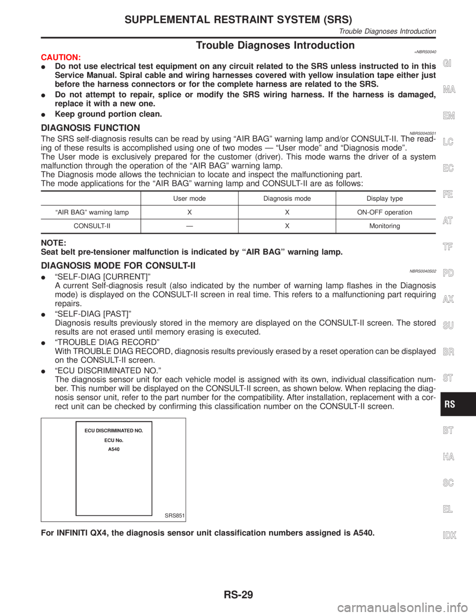
IªECU DISCRIMINATED NO.º
The diagnosis sensor unit for each vehicle model is assigned with its own, individual classification num-
ber. This number will be displayed on the CONSULT-II screen, as shown below. When replacing the diag-
nosis sensor unit, refer to the part number for the compatibility. After installation, replacement with a cor-
rect unit can be checked by confirming this classification number on the CONSULT-II screen.
SRS851
For INFINITI QX4, the diagnosis sensor unit classification numbers assigned is A540.
GI
MA
EM
LC
EC
FE
AT
TF
PD
AX
SU
BR
ST
BT
HA
SC
EL
IDX
SUPPLEMENTAL RESTRAINT SYSTEM (SRS)
Trouble Diagnoses Introduction
RS-29
Page 2120 of 2395
![INFINITI QX4 2001 Factory Service Manual After the malfunction is repaired completely, no malfunction is detected on ªSELF-DIAG [CURRENT]º.
IªSELF-DIAG [PAST]º
Return to the ªSELF-DIAG [CURRENT]º CONSULT-II screen by pushing ªBACKº k INFINITI QX4 2001 Factory Service Manual After the malfunction is repaired completely, no malfunction is detected on ªSELF-DIAG [CURRENT]º.
IªSELF-DIAG [PAST]º
Return to the ªSELF-DIAG [CURRENT]º CONSULT-II screen by pushing ªBACKº k](/img/42/57027/w960_57027-2119.png)
After the malfunction is repaired completely, no malfunction is detected on ªSELF-DIAG [CURRENT]º.
IªSELF-DIAG [PAST]º
Return to the ªSELF-DIAG [CURRENT]º CONSULT-II screen by pushing ªBACKº key of CONSULT-II and
select ªSELF-DIAG [CURRENT]º in SELECT DIAG MODE. Touch ªERASEº in ªSELF-DIAG [CURRENT]º
mode.
NOTE:
If the memory of the malfunction in ªSELF-DIAG [PAST]º is not erased, the User mode shows the sys-
tem malfunction by the operation of the warning lamp even if the malfunction is repaired completely.
SRS701
IªTROUBLE DIAG RECORDº
The memory of ªTROUBLE DIAG RECORDº cannot be erased.
Without CONSULT-IINBRS0040S0502After a malfunction is repaired, switch the ignition ªOFFº for at least one second, then back ªONº. Diagnosis
mode returns to the User mode. At that time, the self-diagnostic result is cleared.
GI
MA
EM
LC
EC
FE
AT
TF
PD
AX
SU
BR
ST
BT
HA
SC
EL
IDX
SUPPLEMENTAL RESTRAINT SYSTEM (SRS)
Trouble Diagnoses Introduction (Cont'd)
RS-31
Page 2122 of 2395

WORK FLOW=NBRS0041S03NOTE:
Seat belt pre-tensioner malfunction is indicated by ªAIR BAGº warning lamp.
SRS799
*1: RS-32
*2: RS-38*3: RS-39
*4: RS-48*5: RS-42
*6: RS-53
GI
MA
EM
LC
EC
FE
AT
TF
PD
AX
SU
BR
ST
BT
HA
SC
EL
IDX
SUPPLEMENTAL RESTRAINT SYSTEM (SRS)
How to Perform Trouble Diagnoses for Quick and Accurate Repair (Cont'd)
RS-33