oil INFINITI QX4 2001 Factory Service Manual
[x] Cancel search | Manufacturer: INFINITI, Model Year: 2001, Model line: QX4, Model: INFINITI QX4 2001Pages: 2395, PDF Size: 43.2 MB
Page 1693 of 2395
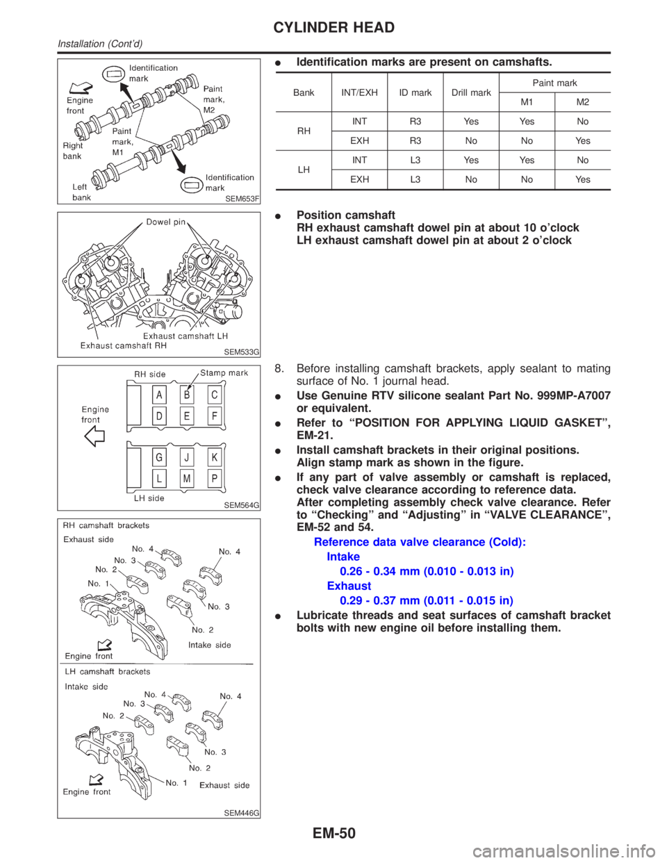
SEM653F
IIdentification marks are present on camshafts.
Bank INT/EXH ID mark Drill markPaint mark
M1 M2
RHINT R3 Yes Yes No
EXH R3 No No Yes
LHINT L3 Yes Yes No
EXH L3 No No Yes
SEM533G
IPosition camshaft
RH exhaust camshaft dowel pin at about 10 o'clock
LH exhaust camshaft dowel pin at about 2 o'clock
SEM564G
SEM446G
8. Before installing camshaft brackets, apply sealant to mating
surface of No. 1 journal head.
IUse Genuine RTV silicone sealant Part No. 999MP-A7007
or equivalent.
IRefer to ªPOSITION FOR APPLYING LIQUID GASKETº,
EM-21.
IInstall camshaft brackets in their original positions.
Align stamp mark as shown in the figure.
IIf any part of valve assembly or camshaft is replaced,
check valve clearance according to reference data.
After completing assembly check valve clearance. Refer
to ªCheckingº and ªAdjustingº in ªVALVE CLEARANCEº,
EM-52 and 54.
Reference data valve clearance (Cold):
Intake
0.26 - 0.34 mm (0.010 - 0.013 in)
Exhaust
0.29 - 0.37 mm (0.011 - 0.015 in)
ILubricate threads and seat surfaces of camshaft bracket
bolts with new engine oil before installing them.
CYLINDER HEAD
Installation (Cont'd)
EM-50
Page 1695 of 2395
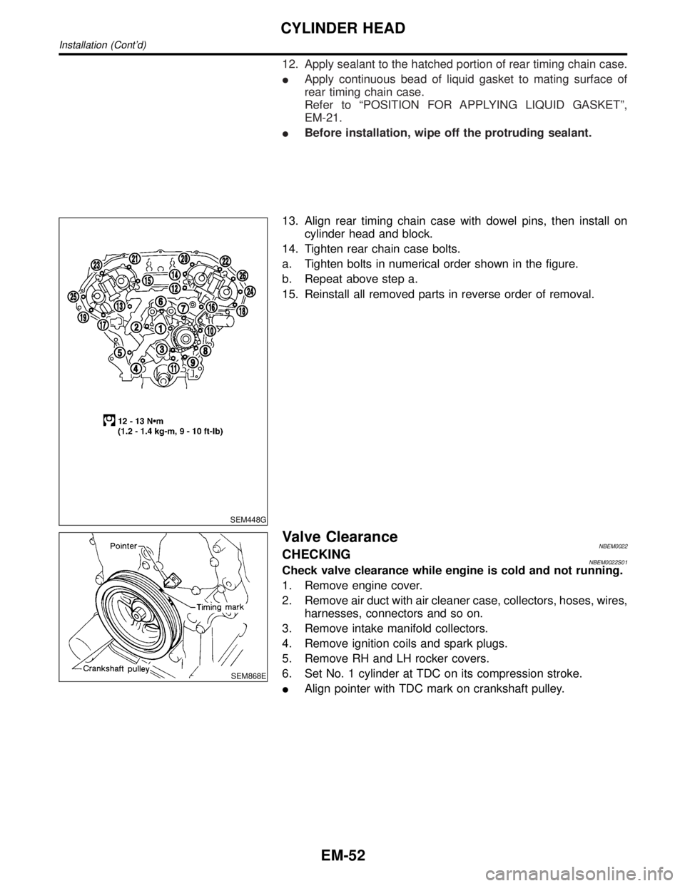
12. Apply sealant to the hatched portion of rear timing chain case.
IApply continuous bead of liquid gasket to mating surface of
rear timing chain case.
Refer to ªPOSITION FOR APPLYING LIQUID GASKETº,
EM-21.
IBefore installation, wipe off the protruding sealant.
SEM448G
13. Align rear timing chain case with dowel pins, then install on
cylinder head and block.
14. Tighten rear chain case bolts.
a. Tighten bolts in numerical order shown in the figure.
b. Repeat above step a.
15. Reinstall all removed parts in reverse order of removal.
SEM868E
Valve ClearanceNBEM0022CHECKINGNBEM0022S01Check valve clearance while engine is cold and not running.
1. Remove engine cover.
2. Remove air duct with air cleaner case, collectors, hoses, wires,
harnesses, connectors and so on.
3. Remove intake manifold collectors.
4. Remove ignition coils and spark plugs.
5. Remove RH and LH rocker covers.
6. Set No. 1 cylinder at TDC on its compression stroke.
IAlign pointer with TDC mark on crankshaft pulley.
CYLINDER HEAD
Installation (Cont'd)
EM-52
Page 1697 of 2395
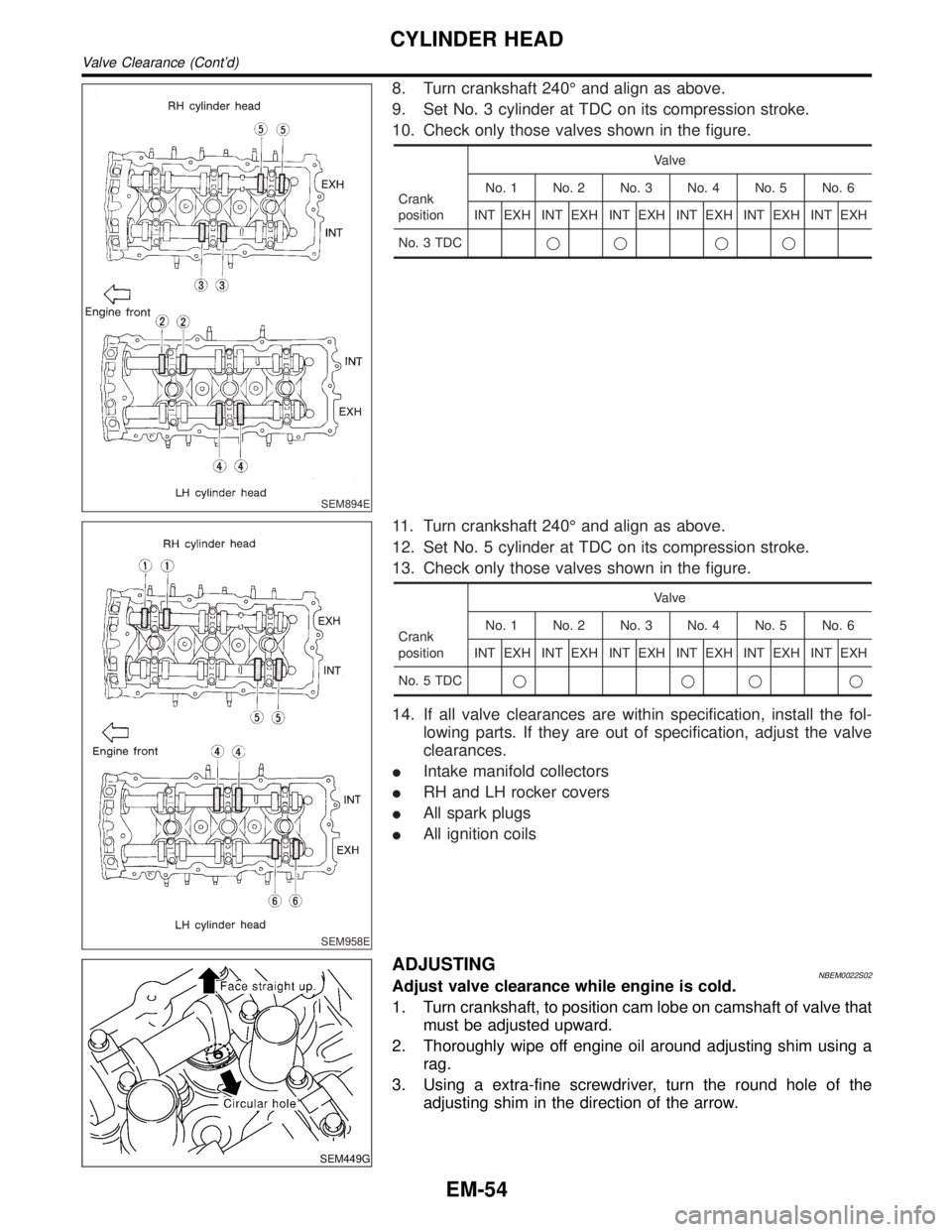
SEM894E
8. Turn crankshaft 240É and align as above.
9. Set No. 3 cylinder at TDC on its compression stroke.
10. Check only those valves shown in the figure.
Crank
positionValve
No. 1 No. 2 No. 3 No. 4 No. 5 No. 6
INT EXH INT EXH INT EXH INT EXH INT EXH INT EXH
No. 3 TDCqq qq
SEM958E
11. Turn crankshaft 240É and align as above.
12. Set No. 5 cylinder at TDC on its compression stroke.
13. Check only those valves shown in the figure.
Crank
positionValve
No. 1 No. 2 No. 3 No. 4 No. 5 No. 6
INT EXH INT EXH INT EXH INT EXH INT EXH INT EXH
No. 5 TDCqqqq
14. If all valve clearances are within specification, install the fol-
lowing parts. If they are out of specification, adjust the valve
clearances.
IIntake manifold collectors
IRH and LH rocker covers
IAll spark plugs
IAll ignition coils
SEM449G
ADJUSTINGNBEM0022S02Adjust valve clearance while engine is cold.
1. Turn crankshaft, to position cam lobe on camshaft of valve that
must be adjusted upward.
2. Thoroughly wipe off engine oil around adjusting shim using a
rag.
3. Using a extra-fine screwdriver, turn the round hole of the
adjusting shim in the direction of the arrow.
CYLINDER HEAD
Valve Clearance (Cont'd)
EM-54
Page 1702 of 2395
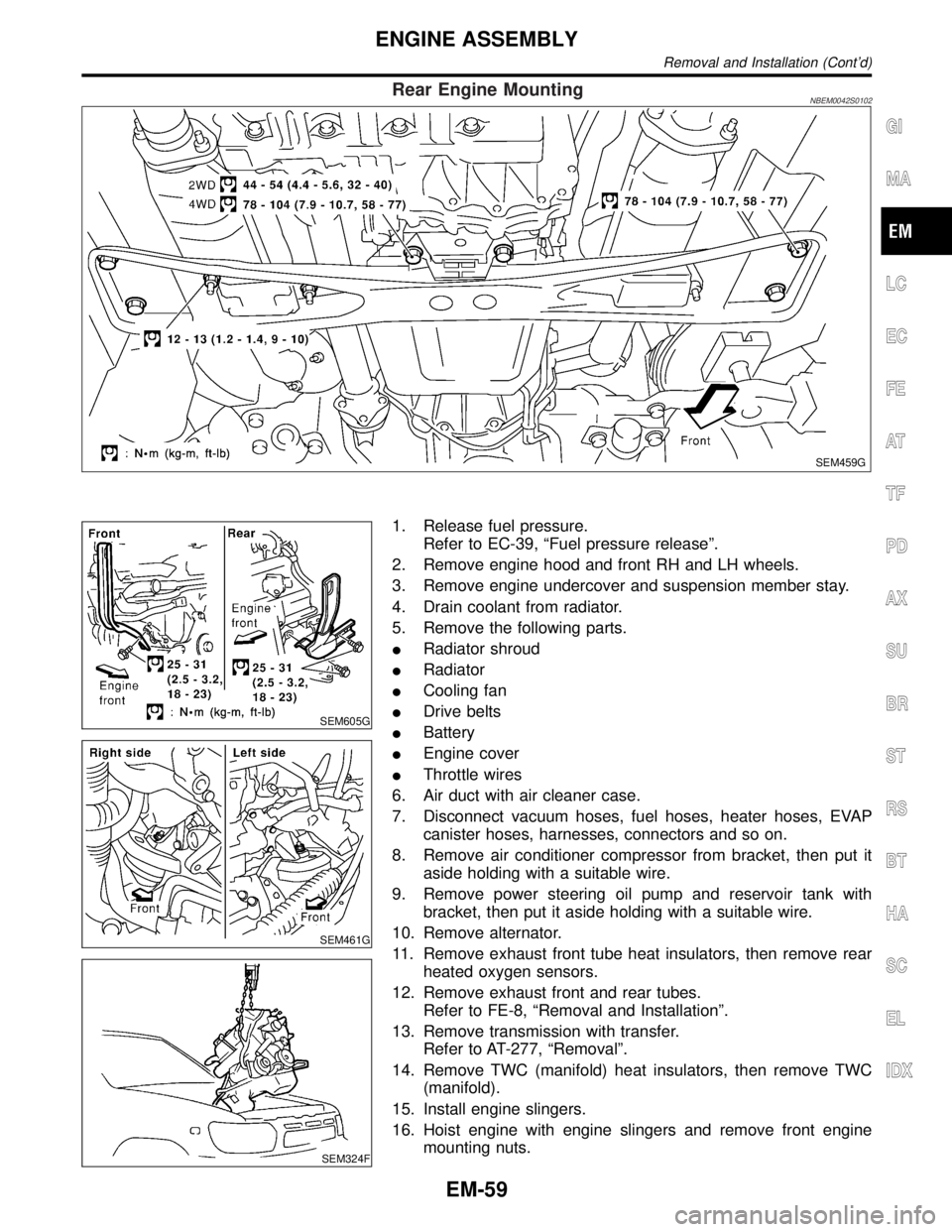
Rear Engine MountingNBEM0042S0102
SEM459G
SEM605G
SEM461G
SEM324F
1. Release fuel pressure.
Refer to EC-39, ªFuel pressure releaseº.
2. Remove engine hood and front RH and LH wheels.
3. Remove engine undercover and suspension member stay.
4. Drain coolant from radiator.
5. Remove the following parts.
IRadiator shroud
IRadiator
ICooling fan
IDrive belts
IBattery
IEngine cover
IThrottle wires
6. Air duct with air cleaner case.
7. Disconnect vacuum hoses, fuel hoses, heater hoses, EVAP
canister hoses, harnesses, connectors and so on.
8. Remove air conditioner compressor from bracket, then put it
aside holding with a suitable wire.
9. Remove power steering oil pump and reservoir tank with
bracket, then put it aside holding with a suitable wire.
10. Remove alternator.
11. Remove exhaust front tube heat insulators, then remove rear
heated oxygen sensors.
12. Remove exhaust front and rear tubes.
Refer to FE-8, ªRemoval and Installationº.
13. Remove transmission with transfer.
Refer to AT-277, ªRemovalº.
14. Remove TWC (manifold) heat insulators, then remove TWC
(manifold).
15. Install engine slingers.
16. Hoist engine with engine slingers and remove front engine
mounting nuts.
GI
MA
LC
EC
FE
AT
TF
PD
AX
SU
BR
ST
RS
BT
HA
SC
EL
IDX
ENGINE ASSEMBLY
Removal and Installation (Cont'd)
EM-59
Page 1704 of 2395
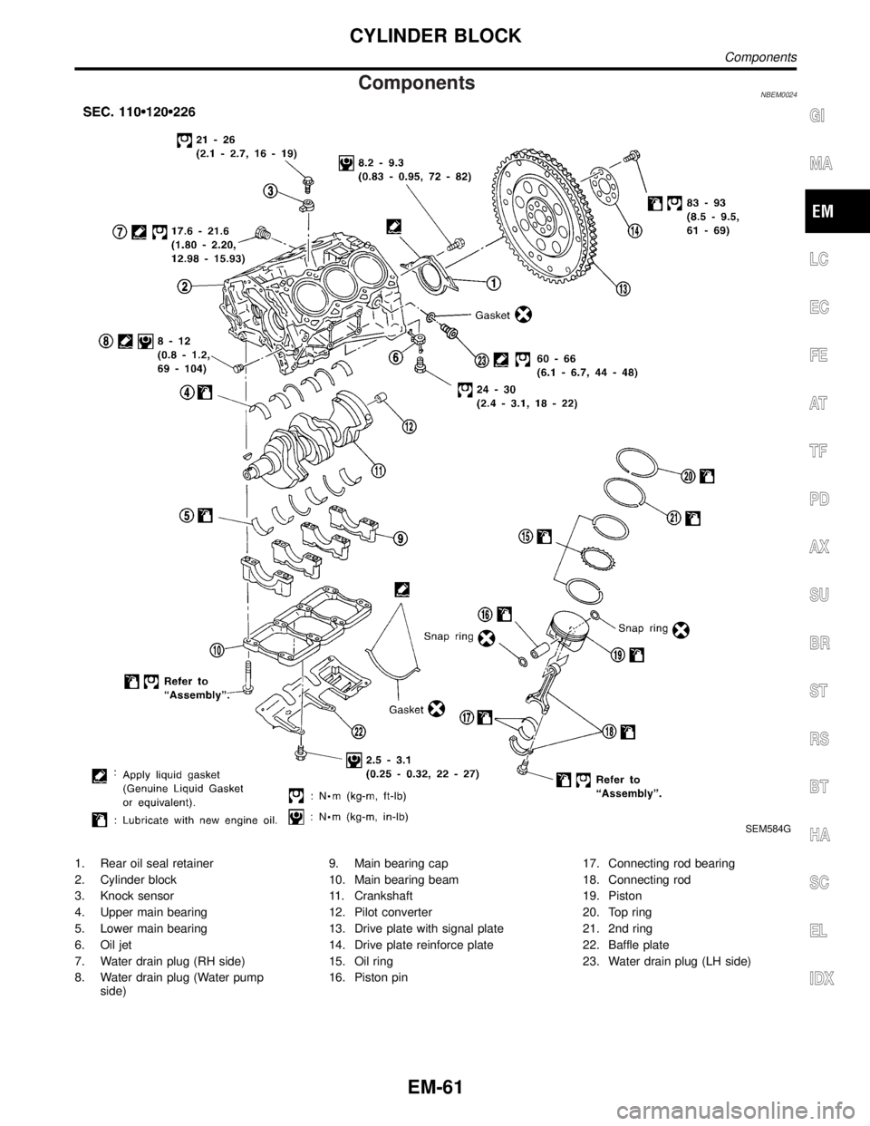
ComponentsNBEM0024
SEM584G
1. Rear oil seal retainer
2. Cylinder block
3. Knock sensor
4. Upper main bearing
5. Lower main bearing
6. Oil jet
7. Water drain plug (RH side)
8. Water drain plug (Water pump
side)9. Main bearing cap
10. Main bearing beam
11. Crankshaft
12. Pilot converter
13. Drive plate with signal plate
14. Drive plate reinforce plate
15. Oil ring
16. Piston pin17. Connecting rod bearing
18. Connecting rod
19. Piston
20. Top ring
21. 2nd ring
22. Baffle plate
23. Water drain plug (LH side)
GI
MA
LC
EC
FE
AT
TF
PD
AX
SU
BR
ST
RS
BT
HA
SC
EL
IDX
CYLINDER BLOCK
Components
EM-61
Page 1705 of 2395
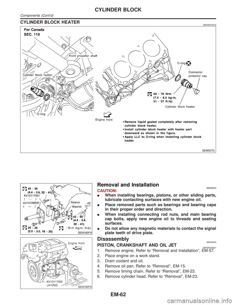
CYLINDER BLOCK HEATERNBEM0024S02
SEM537G
SEM180FA
Removal and InstallationNBEM0025CAUTION:
IWhen installing bearings, pistons, or other sliding parts,
lubricate contacting surfaces with new engine oil.
IPlace removed parts such as bearings and bearing caps
in their proper order and direction.
IWhen installing connecting rod nuts, and main bearing
cap bolts, apply new engine oil to threads and seating
surfaces.
IDo not allow any magnetic materials to contact the signal
plate teeth of drive plate.
SEM190FA
DisassemblyNBEM0026PISTON, CRANKSHAFT AND OIL JETNBEM0026S011. Remove engine. Refer to ªRemoval and Installationº, EM-57.
2. Place engine on a work stand.
3. Drain coolant and oil.
4. Remove oil pan. Refer to ªRemovalº, EM-15.
5. Remove timing chain. Refer to ªRemovalº, EM-23.
6. Remove cylinder head. Refer to ªRemovalº, EM-23.
CYLINDER BLOCK
Components (Cont'd)
EM-62
Page 1706 of 2395
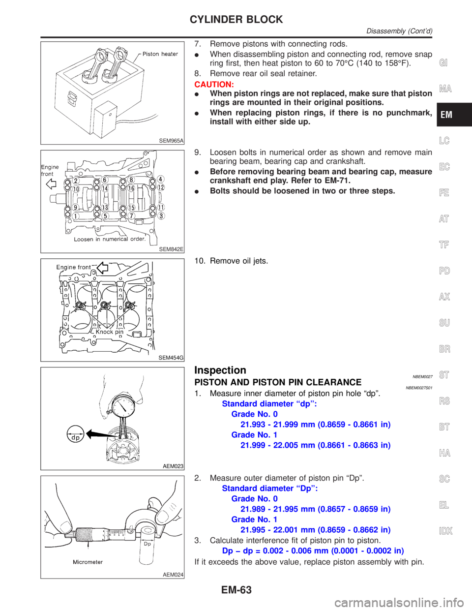
SEM965A
7. Remove pistons with connecting rods.
IWhen disassembling piston and connecting rod, remove snap
ring first, then heat piston to 60 to 70ÉC (140 to 158ÉF).
8. Remove rear oil seal retainer.
CAUTION:
IWhen piston rings are not replaced, make sure that piston
rings are mounted in their original positions.
IWhen replacing piston rings, if there is no punchmark,
install with either side up.
SEM842E
9. Loosen bolts in numerical order as shown and remove main
bearing beam, bearing cap and crankshaft.
IBefore removing bearing beam and bearing cap, measure
crankshaft end play. Refer to EM-71.
IBolts should be loosened in two or three steps.
SEM454G
10. Remove oil jets.
AEM023
InspectionNBEM0027PISTON AND PISTON PIN CLEARANCENBEM0027S011. Measure inner diameter of piston pin hole ªdpº.
Standard diameter ªdpº:
Grade No. 0
21.993 - 21.999 mm (0.8659 - 0.8661 in)
Grade No. 1
21.999 - 22.005 mm (0.8661 - 0.8663 in)
AEM024
2. Measure outer diameter of piston pin ªDpº.
Standard diameter ªDpº:
Grade No. 0
21.989 - 21.995 mm (0.8657 - 0.8659 in)
Grade No. 1
21.995 - 22.001 mm (0.8659 - 0.8662 in)
3. Calculate interference fit of piston pin to piston.
Dp þ dp = 0.002 - 0.006 mm (0.0001 - 0.0002 in)
If it exceeds the above value, replace piston assembly with pin.
GI
MA
LC
EC
FE
AT
TF
PD
AX
SU
BR
ST
RS
BT
HA
SC
EL
IDX
CYLINDER BLOCK
Disassembly (Cont'd)
EM-63
Page 1707 of 2395
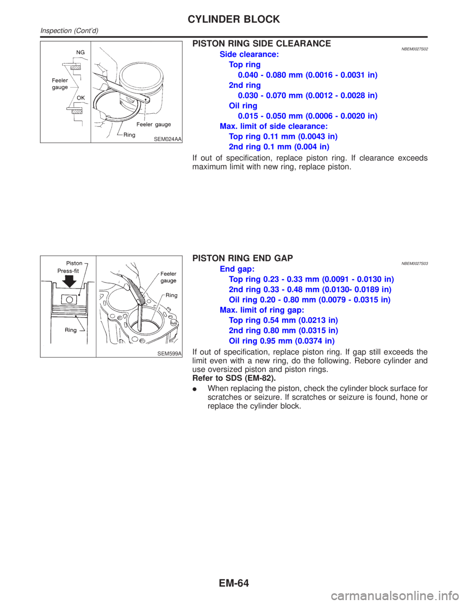
SEM024AA
PISTON RING SIDE CLEARANCENBEM0027S02Side clearance:
Top ring
0.040 - 0.080 mm (0.0016 - 0.0031 in)
2nd ring
0.030 - 0.070 mm (0.0012 - 0.0028 in)
Oil ring
0.015 - 0.050 mm (0.0006 - 0.0020 in)
Max. limit of side clearance:
Top ring 0.11 mm (0.0043 in)
2nd ring 0.1 mm (0.004 in)
If out of specification, replace piston ring. If clearance exceeds
maximum limit with new ring, replace piston.
SEM599A
PISTON RING END GAPNBEM0027S03End gap:
Top ring 0.23 - 0.33 mm (0.0091 - 0.0130 in)
2nd ring 0.33 - 0.48 mm (0.0130- 0.0189 in)
Oil ring 0.20 - 0.80 mm (0.0079 - 0.0315 in)
Max. limit of ring gap:
Top ring 0.54 mm (0.0213 in)
2nd ring 0.80 mm (0.0315 in)
Oil ring 0.95 mm (0.0374 in)
If out of specification, replace piston ring. If gap still exceeds the
limit even with a new ring, do the following. Rebore cylinder and
use oversized piston and piston rings.
Refer to SDS (EM-82).
IWhen replacing the piston, check the cylinder block surface for
scratches or seizure. If scratches or seizure is found, hone or
replace the cylinder block.
CYLINDER BLOCK
Inspection (Cont'd)
EM-64
Page 1714 of 2395
SEM838F
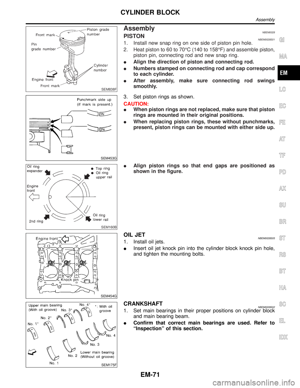
AssemblyNBEM0028PISTONNBEM0028S011. Install new snap ring on one side of piston pin hole.
2. Heat piston to 60 to 70ÉC (140 to 158ÉF) and assemble piston,
piston pin, connecting rod and new snap ring.
IAlign the direction of piston and connecting rod.
INumbers stamped on connecting rod and cap correspond
to each cylinder.
IAfter assembly, make sure connecting rod swings
smoothly.
SEM453G
3. Set piston rings as shown.
CAUTION:
IWhen piston rings are not replaced, make sure that piston
rings are mounted in their original positions.
IWhen replacing piston rings, these without punchmarks,
present, piston rings can be mounted with either side up.
SEM160B
IAlign piston rings so that end gaps are positioned as
shown in the figure.
SEM454G
OIL JETNBEM0028S051. Install oil jets.
IInsert oil jet knock pin into the cylinder block knock pin hole,
and tighten the mounting bolts.
SEM175F
CRANKSHAFTNBEM0028S021. Set main bearings in their proper positions on cylinder block
and main bearing beam.
IConfirm that correct main bearings are used. Refer to
ªInspectionº of this section.
GI
MA
LC
EC
FE
AT
TF
PD
AX
SU
BR
ST
RS
BT
HA
SC
EL
IDX
CYLINDER BLOCK
Assembly
EM-71
Page 1715 of 2395
SEM177F
SEM456G
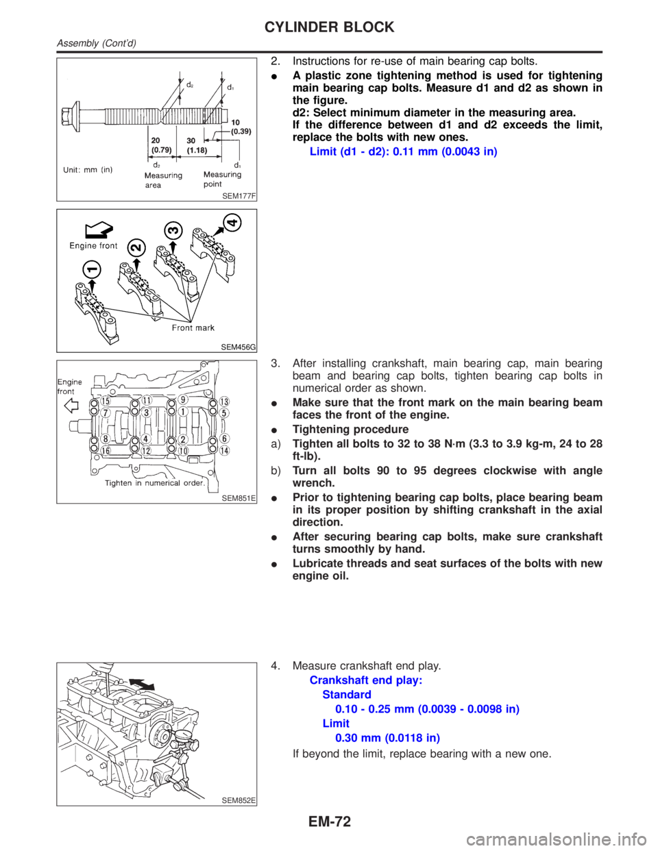
2. Instructions for re-use of main bearing cap bolts.
IA plastic zone tightening method is used for tightening
main bearing cap bolts. Measure d1 and d2 as shown in
the figure.
d2: Select minimum diameter in the measuring area.
If the difference between d1 and d2 exceeds the limit,
replace the bolts with new ones.
Limit (d1 - d2): 0.11 mm (0.0043 in)
SEM851E
3. After installing crankshaft, main bearing cap, main bearing
beam and bearing cap bolts, tighten bearing cap bolts in
numerical order as shown.
IMake sure that the front mark on the main bearing beam
faces the front of the engine.
ITightening procedure
a)Tighten all bolts to 32 to 38 N´m (3.3 to 3.9 kg-m, 24 to 28
ft-lb).
b)Turn all bolts 90 to 95 degrees clockwise with angle
wrench.
IPrior to tightening bearing cap bolts, place bearing beam
in its proper position by shifting crankshaft in the axial
direction.
IAfter securing bearing cap bolts, make sure crankshaft
turns smoothly by hand.
ILubricate threads and seat surfaces of the bolts with new
engine oil.
SEM852E
4. Measure crankshaft end play.
Crankshaft end play:
Standard
0.10 - 0.25 mm (0.0039 - 0.0098 in)
Limit
0.30 mm (0.0118 in)
If beyond the limit, replace bearing with a new one.
CYLINDER BLOCK
Assembly (Cont'd)
EM-72