Battery INFINITI QX4 2001 Factory Owner's Guide
[x] Cancel search | Manufacturer: INFINITI, Model Year: 2001, Model line: QX4, Model: INFINITI QX4 2001Pages: 2395, PDF Size: 43.2 MB
Page 194 of 2395

5 CHECK TCM INSPECTION
1. Perform TCM input/output signal inspection.
2. If NG, recheck TCM pin terminals for damage or loose connection with harness connector.
OK or NG
OK©INSPECTION END
NG©Repair or replace damaged parts.
SAT139K
Component InspectionNBAT0070OVERRUN CLUTCH SOLENOID VALVENBAT0070S01IFor removal, refer to AT-273.
Resistance CheckNBAT0070S0101ICheck resistance between terminal 4 and ground.
Solenoid valve Terminal No. Resistance (Approx.)
Overrun clutch solenoid valve 4 Ground 20 - 40W
SAT688I
Operation CheckNBAT0070S0102ICheck solenoid valve by listening for its operating sound while
applying battery voltage to the terminal 4 and ground.
GI
MA
EM
LC
EC
FE
TF
PD
AX
SU
BR
ST
RS
BT
HA
SC
EL
IDX
DTC P1760 OVERRUN CLUTCH SOLENOID VALVE
Diagnostic Procedure (Cont'd)
AT-189
Page 195 of 2395
SAT342HA
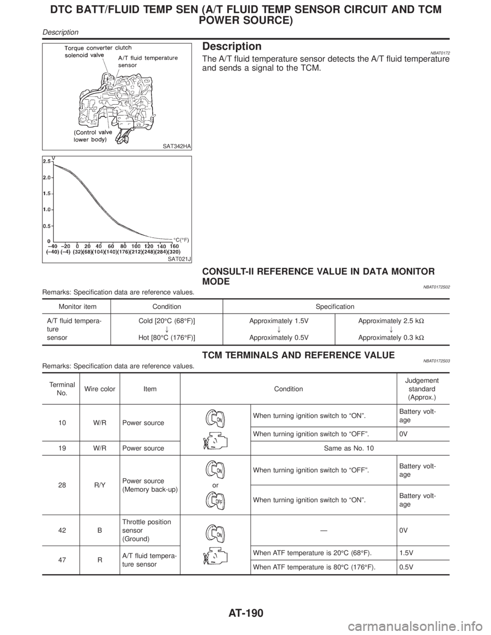
DescriptionNBAT0172The A/T fluid temperature sensor detects the A/T fluid temperature
and sends a signal to the TCM.
SAT021J
CONSULT-II REFERENCE VALUE IN DATA MONITOR
MODE
NBAT0172S02Remarks: Specification data are reference values.
Monitor item Condition Specification
A/T fluid tempera-
ture
sensorCold [20ÉC (68ÉF)]
"
Hot [80ÉC (176ÉF)]Approximately 1.5V
"
Approximately 0.5VApproximately 2.5 kW
"
Approximately 0.3 kW
TCM TERMINALS AND REFERENCE VALUENBAT0172S03Remarks: Specification data are reference values.
Terminal
No.Wire color Item ConditionJudgement
standard
(Approx.)
10 W/R Power source
When turning ignition switch to ªONº.Battery volt-
age
When turning ignition switch to ªOFFº. 0V
19 W/R Power source Same as No. 10
28 R/YPower source
(Memory back-up)
or
When turning ignition switch to ªOFFº.Battery volt-
age
When turning ignition switch to ªONº.Battery volt-
age
42 BThrottle position
sensor
(Ground)
Ð0V
47 RA/T fluid tempera-
ture sensorWhen ATF temperature is 20ÉC (68ÉF). 1.5V
When ATF temperature is 80ÉC (176ÉF). 0.5V
DTC BATT/FLUID TEMP SEN (A/T FLUID TEMP SENSOR CIRCUIT AND TCM
POWER SOURCE)
Description
AT-190
Page 205 of 2395
Diagnostic ProcedureNBAT0072
1 CHECK INPUT SIGNAL.
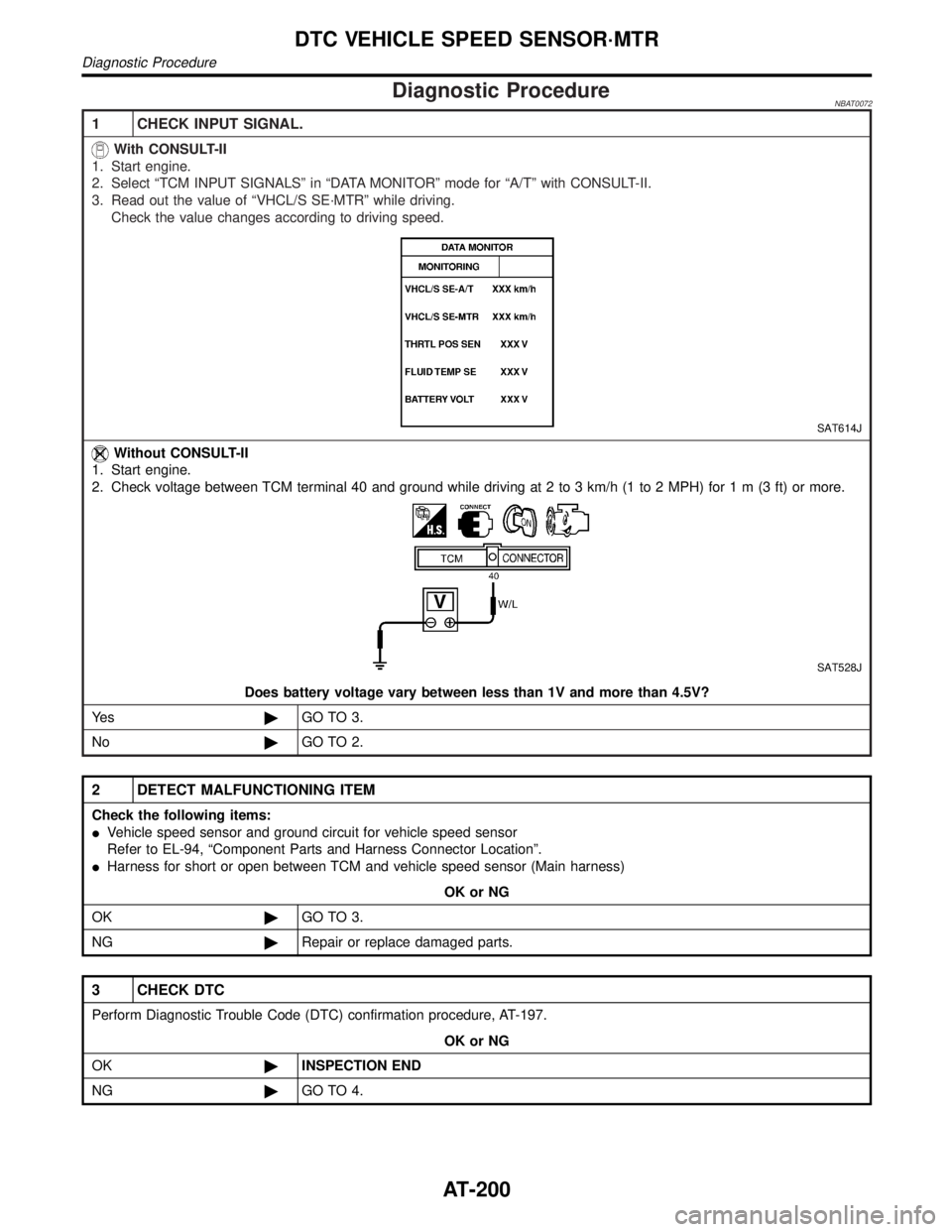
With CONSULT-II
1. Start engine.
2. Select ªTCM INPUT SIGNALSº in ªDATA MONITORº mode for ªA/Tº with CONSULT-II.
3. Read out the value of ªVHCL/S SE´MTRº while driving.
Check the value changes according to driving speed.
SAT614J
Without CONSULT-II
1. Start engine.
2. Check voltage between TCM terminal 40 and ground while driving at 2 to 3 km/h (1 to 2 MPH) for1m(3ft)ormore.
SAT528J
Does battery voltage vary between less than 1V and more than 4.5V?
Ye s©GO TO 3.
No©GO TO 2.
2 DETECT MALFUNCTIONING ITEM
Check the following items:
IVehicle speed sensor and ground circuit for vehicle speed sensor
Refer to EL-94, ªComponent Parts and Harness Connector Locationº.
IHarness for short or open between TCM and vehicle speed sensor (Main harness)
OK or NG
OK©GO TO 3.
NG©Repair or replace damaged parts.
3 CHECK DTC
Perform Diagnostic Trouble Code (DTC) confirmation procedure, AT-197.
OK or NG
OK©INSPECTION END
NG©GO TO 4.
DTC VEHICLE SPEED SENSOR´MTR
Diagnostic Procedure
AT-200
Page 224 of 2395
4 CHECK TCM GROUND CIRCUIT
1. Turn ignition switch to OFF position.
2. Disconnect TCM harness connector.
3. Check continuity between TCM terminals 25, 48 and ground. Refer to wiring diagram Ð AT Ð MAIN.
Continuity should exist.
If OK, check harness for short to ground and short to power.
OK or NG
OK©GO TO 5.
NG©Repair open circuit or short to ground or short to power in harness or connectors.
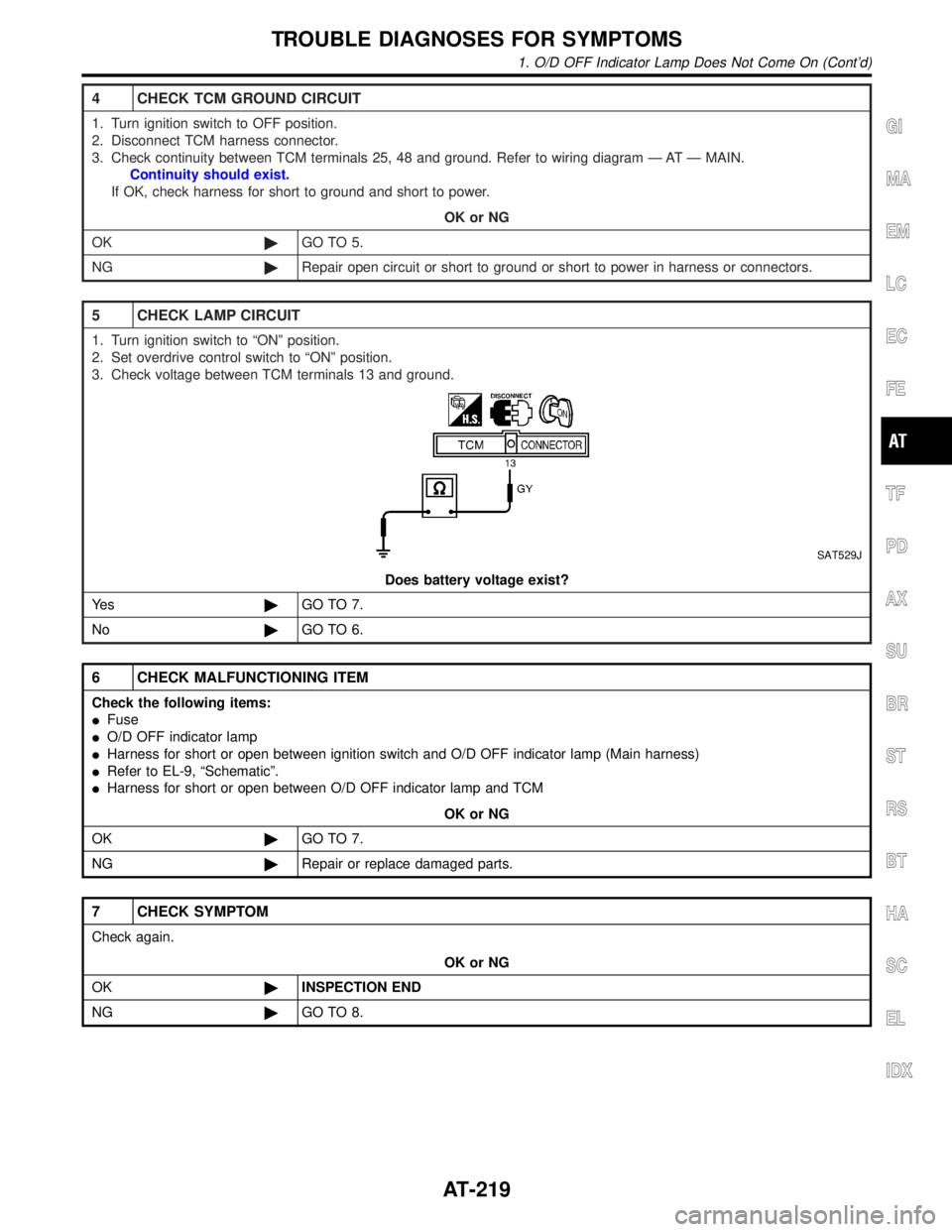
5 CHECK LAMP CIRCUIT
1. Turn ignition switch to ªONº position.
2. Set overdrive control switch to ªONº position.
3. Check voltage between TCM terminals 13 and ground.
SAT529J
Does battery voltage exist?
Ye s©GO TO 7.
No©GO TO 6.
6 CHECK MALFUNCTIONING ITEM
Check the following items:
IFuse
IO/D OFF indicator lamp
IHarness for short or open between ignition switch and O/D OFF indicator lamp (Main harness)
IRefer to EL-9, ªSchematicº.
IHarness for short or open between O/D OFF indicator lamp and TCM
OK or NG
OK©GO TO 7.
NG©Repair or replace damaged parts.
7 CHECK SYMPTOM
Check again.
OK or NG
OK©INSPECTION END
NG©GO TO 8.
GI
MA
EM
LC
EC
FE
TF
PD
AX
SU
BR
ST
RS
BT
HA
SC
EL
IDX
TROUBLE DIAGNOSES FOR SYMPTOMS
1. O/D OFF Indicator Lamp Does Not Come On (Cont'd)
AT-219
Page 264 of 2395
3 CHECK PNP SWITCH CIRCUIT (Without CONSULT-II)
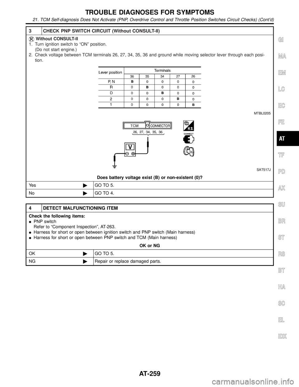
Without CONSULT-II
1. Turn ignition switch to ªONº position.
(Do not start engine.)
2. Check voltage between TCM terminals 26, 27, 34, 35, 36 and ground while moving selector lever through each posi-
tion.
MTBL0205
SAT517J
Does battery voltage exist (B) or non-existent (0)?
Ye s©GO TO 5.
No©GO TO 4.
4 DETECT MALFUNCTIONING ITEM
Check the following items:
IPNP switch
Refer to ªComponent Inspectionº, AT-263.
IHarness for short or open between ignition switch and PNP switch (Main harness)
IHarness for short or open between PNP switch and TCM (Main harness)
OK or NG
OK©GO TO 5.
NG©Repair or replace damaged parts.
GI
MA
EM
LC
EC
FE
TF
PD
AX
SU
BR
ST
RS
BT
HA
SC
EL
IDX
TROUBLE DIAGNOSES FOR SYMPTOMS
21. TCM Self-diagnosis Does Not Activate (PNP, Overdrive Control and Throttle Position Switches Circuit Checks) (Cont'd)
AT-259
Page 265 of 2395
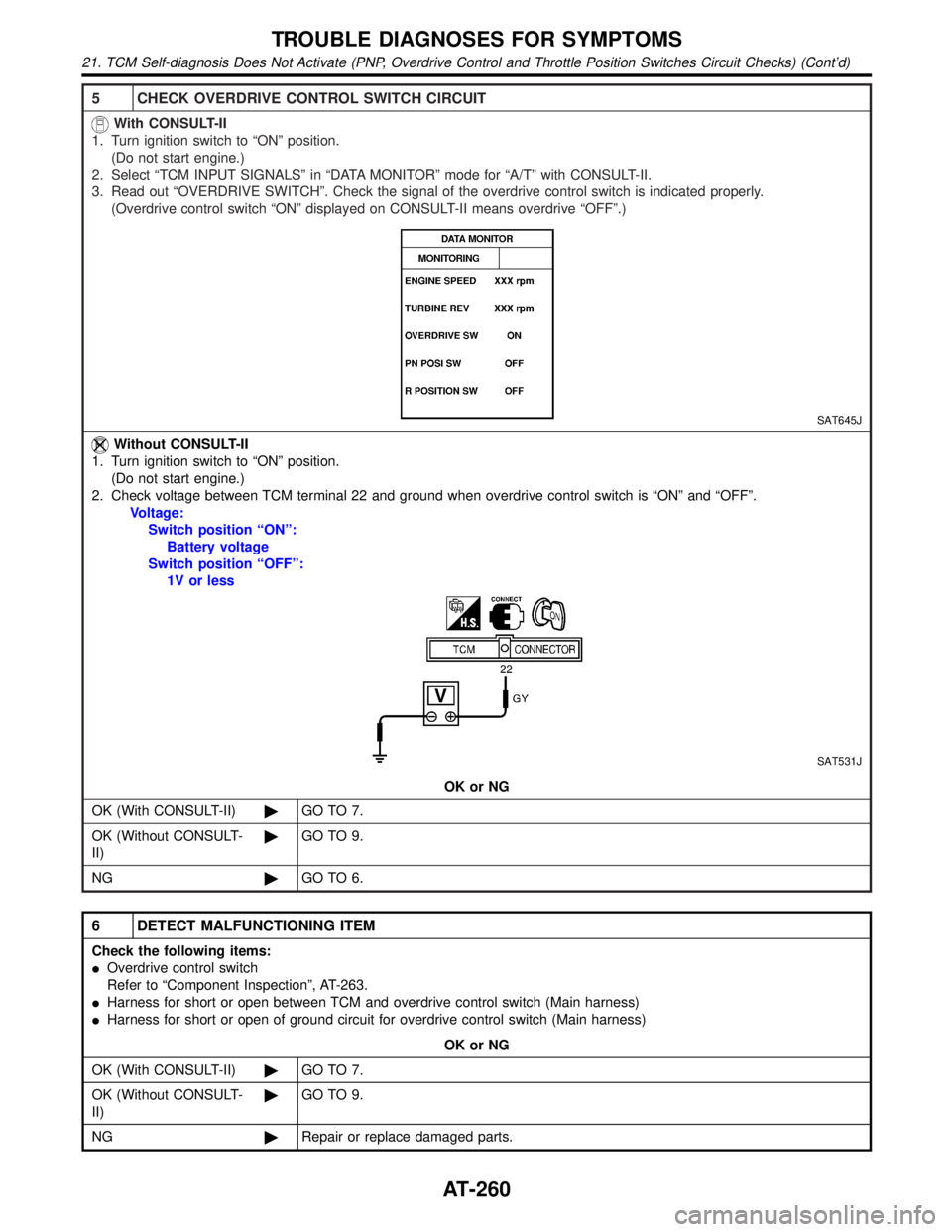
5 CHECK OVERDRIVE CONTROL SWITCH CIRCUIT
With CONSULT-II
1. Turn ignition switch to ªONº position.
(Do not start engine.)
2. Select ªTCM INPUT SIGNALSº in ªDATA MONITORº mode for ªA/Tº with CONSULT-II.
3. Read out ªOVERDRIVE SWITCHº. Check the signal of the overdrive control switch is indicated properly.
(Overdrive control switch ªONº displayed on CONSULT-II means overdrive ªOFFº.)
SAT645J
Without CONSULT-II
1. Turn ignition switch to ªONº position.
(Do not start engine.)
2. Check voltage between TCM terminal 22 and ground when overdrive control switch is ªONº and ªOFFº.
Voltage:
Switch position ªONº:
Battery voltage
Switch position ªOFFº:
1V or less
SAT531J
OK or NG
OK (With CONSULT-II)©GO TO 7.
OK (Without CONSULT-
II)©GO TO 9.
NG©GO TO 6.
6 DETECT MALFUNCTIONING ITEM
Check the following items:
IOverdrive control switch
Refer to ªComponent Inspectionº, AT-263.
IHarness for short or open between TCM and overdrive control switch (Main harness)
IHarness for short or open of ground circuit for overdrive control switch (Main harness)
OK or NG
OK (With CONSULT-II)©GO TO 7.
OK (Without CONSULT-
II)©GO TO 9.
NG©Repair or replace damaged parts.
TROUBLE DIAGNOSES FOR SYMPTOMS
21. TCM Self-diagnosis Does Not Activate (PNP, Overdrive Control and Throttle Position Switches Circuit Checks) (Cont'd)
AT-260
Page 273 of 2395
![INFINITI QX4 2001 Factory Owners Guide 4 DETECT MALFUNCTIONING ITEM
Check the following items:
1. Harness for short or open between ignition switch and A/T device harness terminal 5
2. 7.5A fuse [No. 11, located in the fuse block (J/B)]
3. INFINITI QX4 2001 Factory Owners Guide 4 DETECT MALFUNCTIONING ITEM
Check the following items:
1. Harness for short or open between ignition switch and A/T device harness terminal 5
2. 7.5A fuse [No. 11, located in the fuse block (J/B)]
3.](/img/42/57027/w960_57027-272.png)
4 DETECT MALFUNCTIONING ITEM
Check the following items:
1. Harness for short or open between ignition switch and A/T device harness terminal 5
2. 7.5A fuse [No. 11, located in the fuse block (J/B)]
3. Ignition switch (Refer to EL-9, ªSchematicº.)
OK or NG
OK©GO TO 5.
NG©Repair or replace damaged parts.
5 CHECK INPUT SIGNAL A/T DEVICE
Turn ignition switch to OFF position.
ICheck voltage between A/T device harness terminal 7 and ground.
SAT179K
OK or NG
OK©GO TO 7.
NG©GO TO 6.
6 DETECT MALFUNCTIONING ITEM
Check the following items:
1. Harness for short or open between battery and stop lamp switch harness connector 1
2. Harness for short or open between stop lamp switch harness connector 2 and A/T device harness connector 7
3. Diode
4. 10A fuse [No. 14, located in the fuse block (J/B)]
5. Stop lamp switch
a. Check continuity between terminals 1 and 2.
SAT146K
Check stop lamp switch after adjusting brake pedal Ð refer to BR-14, ªAdjustmentº.
OK or NG
OK©GO TO 7.
NG©Repair or replace damaged parts.
A/T SHIFT LOCK SYSTEM
Diagnostic Procedure (Cont'd)
AT-268
Page 275 of 2395
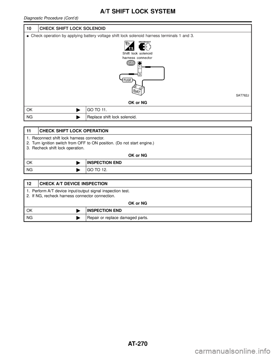
10 CHECK SHIFT LOCK SOLENOID
ICheck operation by applying battery voltage shift lock solenoid harness terminals 1 and 3.
SAT762J
OK or NG
OK©GO TO 11.
NG©Replace shift lock solenoid.
11 CHECK SHIFT LOCK OPERATION
1. Reconnect shift lock harness connector.
2. Turn ignition switch from OFF to ON position. (Do not start engine.)
3. Recheck shift lock operation.
OK or NG
OK©INSPECTION END
NG©GO TO 12.
12 CHECK A/T DEVICE INSPECTION
1. Perform A/T device input/output signal inspection test.
2. If NG, recheck harness connector connection.
OK or NG
OK©INSPECTION END
NG©Repair or replace damaged parts.
A/T SHIFT LOCK SYSTEM
Diagnostic Procedure (Cont'd)
AT-270
Page 282 of 2395
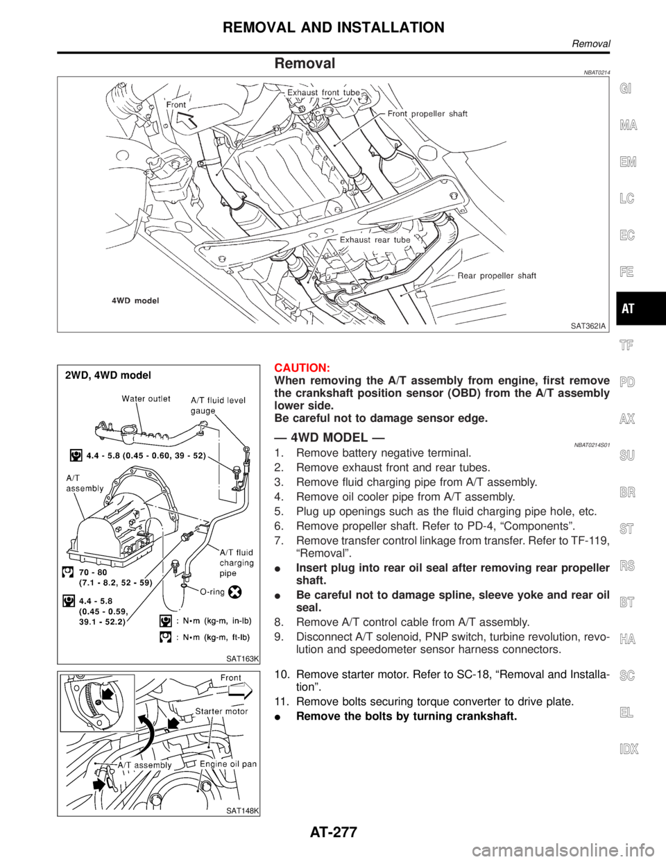
RemovalNBAT0214
SAT362IA
SAT163K
CAUTION:
When removing the A/T assembly from engine, first remove
the crankshaft position sensor (OBD) from the A/T assembly
lower side.
Be careful not to damage sensor edge.
Ð 4WD MODEL ÐNBAT0214S011. Remove battery negative terminal.
2. Remove exhaust front and rear tubes.
3. Remove fluid charging pipe from A/T assembly.
4. Remove oil cooler pipe from A/T assembly.
5. Plug up openings such as the fluid charging pipe hole, etc.
6. Remove propeller shaft. Refer to PD-4, ªComponentsº.
7. Remove transfer control linkage from transfer. Refer to TF-119,
ªRemovalº.
IInsert plug into rear oil seal after removing rear propeller
shaft.
IBe careful not to damage spline, sleeve yoke and rear oil
seal.
8. Remove A/T control cable from A/T assembly.
9. Disconnect A/T solenoid, PNP switch, turbine revolution, revo-
lution and speedometer sensor harness connectors.
SAT148K
10. Remove starter motor. Refer to SC-18, ªRemoval and Installa-
tionº.
11. Remove bolts securing torque converter to drive plate.
IRemove the bolts by turning crankshaft.
GI
MA
EM
LC
EC
FE
TF
PD
AX
SU
BR
ST
RS
BT
HA
SC
EL
IDX
REMOVAL AND INSTALLATION
Removal
AT-277
Page 283 of 2395
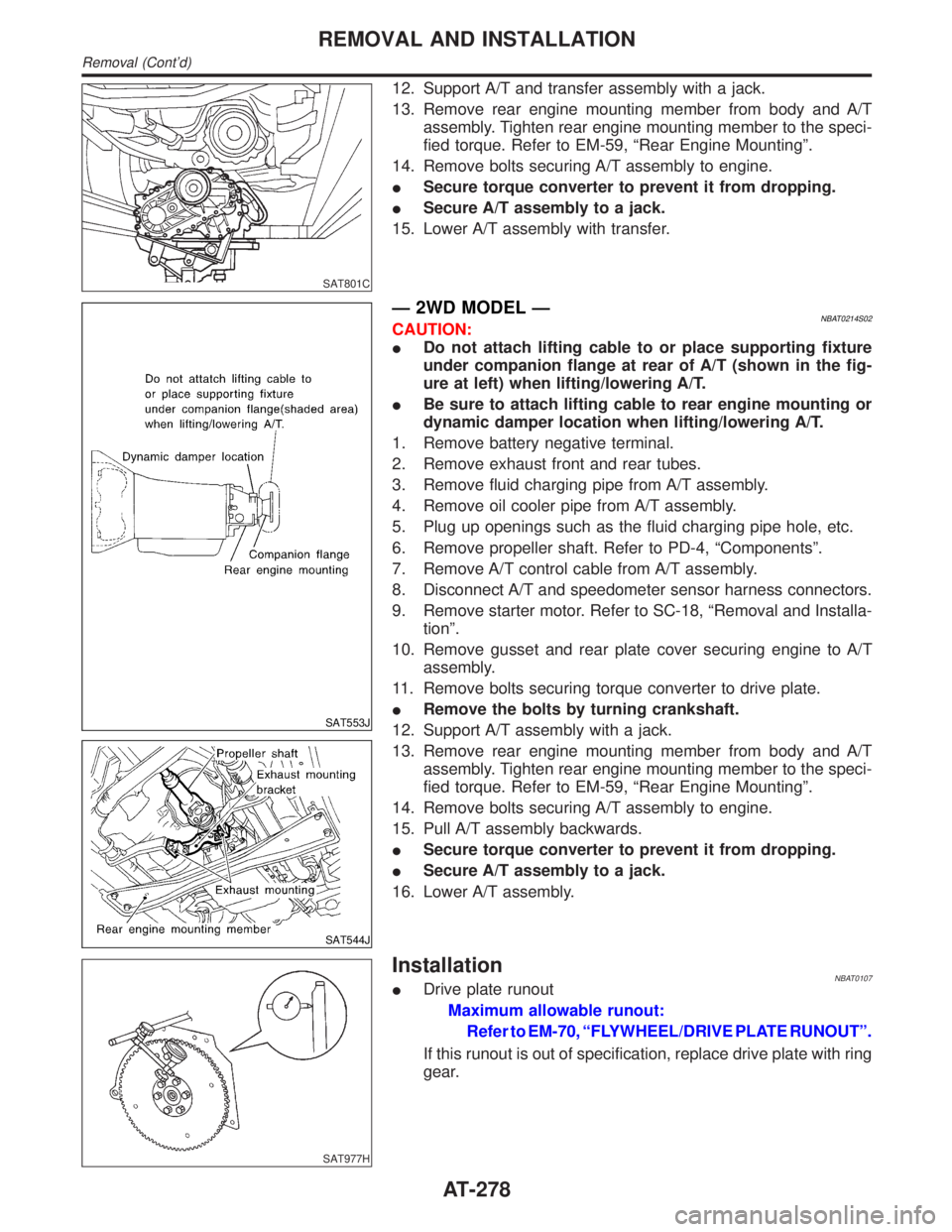
SAT801C
12. Support A/T and transfer assembly with a jack.
13. Remove rear engine mounting member from body and A/T
assembly. Tighten rear engine mounting member to the speci-
fied torque. Refer to EM-59, ªRear Engine Mountingº.
14. Remove bolts securing A/T assembly to engine.
ISecure torque converter to prevent it from dropping.
ISecure A/T assembly to a jack.
15. Lower A/T assembly with transfer.
SAT553J
SAT544J
Ð 2WD MODEL ÐNBAT0214S02CAUTION:
IDo not attach lifting cable to or place supporting fixture
under companion flange at rear of A/T (shown in the fig-
ure at left) when lifting/lowering A/T.
IBe sure to attach lifting cable to rear engine mounting or
dynamic damper location when lifting/lowering A/T.
1. Remove battery negative terminal.
2. Remove exhaust front and rear tubes.
3. Remove fluid charging pipe from A/T assembly.
4. Remove oil cooler pipe from A/T assembly.
5. Plug up openings such as the fluid charging pipe hole, etc.
6. Remove propeller shaft. Refer to PD-4, ªComponentsº.
7. Remove A/T control cable from A/T assembly.
8. Disconnect A/T and speedometer sensor harness connectors.
9. Remove starter motor. Refer to SC-18, ªRemoval and Installa-
tionº.
10. Remove gusset and rear plate cover securing engine to A/T
assembly.
11. Remove bolts securing torque converter to drive plate.
IRemove the bolts by turning crankshaft.
12. Support A/T assembly with a jack.
13. Remove rear engine mounting member from body and A/T
assembly. Tighten rear engine mounting member to the speci-
fied torque. Refer to EM-59, ªRear Engine Mountingº.
14. Remove bolts securing A/T assembly to engine.
15. Pull A/T assembly backwards.
ISecure torque converter to prevent it from dropping.
ISecure A/T assembly to a jack.
16. Lower A/T assembly.
SAT977H
InstallationNBAT0107IDrive plate runout
Maximum allowable runout:
Refer to EM-70, ªFLYWHEEL/DRIVE PLATE RUNOUTº.
If this runout is out of specification, replace drive plate with ring
gear.
REMOVAL AND INSTALLATION
Removal (Cont'd)
AT-278