Battery INFINITI QX4 2001 Factory Repair Manual
[x] Cancel search | Manufacturer: INFINITI, Model Year: 2001, Model line: QX4, Model: INFINITI QX4 2001Pages: 2395, PDF Size: 43.2 MB
Page 570 of 2395

SEF462UA
SEF598U
Without CONSULT-IINBEC0019S08021) Attach the EVAP service port adapter securely to the EVAP
service port.
2) Also attach the pressure pump with pressure gauge to the
EVAP service port adapter.
3) Apply battery voltage to between the terminals of both EVAP
canister vent control valve and vacuum cut valve bypass valve
to make a closed EVAP system.
4) To locate the leak, deliver positive pressure to the EVAP sys-
tem until pressure gauge points reach 1.38 to 2.76 kPa (0.014
to 0.028 kg/cm
2, 0.2 to 0.4 psi).
5) Remove EVAP service port adapter and hose with pressure
pump.
6) Locate the leak using a leak detector. Refer to ªEVAPORATIVE
EMISSION LINE DRAWINGº, EC-36.
GI
MA
EM
LC
FE
AT
TF
PD
AX
SU
BR
ST
RS
BT
HA
SC
EL
IDX
ENGINE AND EMISSION BASIC CONTROL SYSTEM DESCRIPTION
Evaporative Emission System (Cont'd)
EC-35
Page 578 of 2395

SEF943Y
SEF572X
b) Connect No. 1 ignition coil and No. 1 spark plug with suitable
high-tension wire as shown, and attach timing light clamp to
this wire.
c) Check ignition timing.
SEF311Q
Idle Speed/Ignition Timing/Idle Mixture Ratio
Adjustment
NBEC0028PREPARATIONNBEC0028S011) Make sure that the following parts are in good order.
IBattery
IIgnition system
IEngine oil and coolant levels
IFuses
IECM harness connector
IVacuum hoses
GI
MA
EM
LC
FE
AT
TF
PD
AX
SU
BR
ST
RS
BT
HA
SC
EL
IDX
BASIC SERVICE PROCEDURE
How to Check Idle Speed and Ignition Timing (Cont'd)
EC-43
Page 588 of 2395

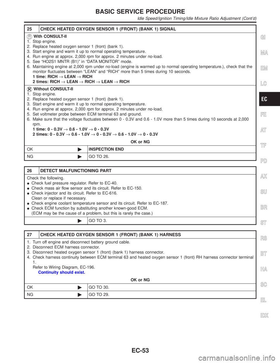
25 CHECK HEATED OXYGEN SENSOR 1 (FRONT) (BANK 1) SIGNAL
With CONSULT-II
1. Stop engine.
2. Replace heated oxygen sensor 1 (front) (bank 1).
3. Start engine and warm it up to normal operating temperature.
4. Run engine at approx. 2,000 rpm for approx. 2 minutes under no-load.
5. See ªHO2S1 MNTR (B1)º in ªDATA MONITORº mode.
6. Maintaining engine at 2,000 rpm under no-load (engine is warmed up to normal operating temperature.), check that the
monitor fluctuates between ªLEANº and ªRICHº more than 5 times during 10 seconds.
1 time: RICH®LEAN®RICH
2 times: RICH®LEAN®RICH®LEAN®RICH
Without CONSULT-II
1. Stop engine.
2. Replace heated oxygen sensor 1 (front) (bank 1).
3. Start engine and warm it up to normal operating temperature.
4. Run engine at approx. 2,000 rpm for approx. 2 minutes under no-load.
5. Set voltmeter probe between ECM terminal 63 and ground.
6. Make sure that the voltage fluctuates between 0 - 0.3V and 0.6 - 1.0V more than 5 times during 10 seconds at 2,000
rpm.
1 time: 0 - 0.3V®0.6 - 1.0V®0 - 0.3V
2 times: 0 - 0.3V®0.6 - 1.0V®0 - 0.3V®0.6 - 1.0V®0 - 0.3V
OK or NG
OK©INSPECTION END
NG©GO TO 26.
26 DETECT MALFUNCTIONING PART
Check the following.
ICheck fuel pressure regulator. Refer to EC-40.
ICheck mass air flow sensor and its circuit. Refer to EC-150.
ICheck injector and its circuit. Refer to EC-616.
Clean or replace if necessary.
ICheck engine coolant temperature sensor and its circuit. Refer to EC-187.
ICheck ECM function by substituting another known-good ECM.
(ECM may be the cause of a problem, but this is rarely the case.)
©GO TO 3.
27 CHECK HEATED OXYGEN SENSOR 1 (FRONT) (BANK 1) HARNESS
1. Turn off engine and disconnect battery ground cable.
2. Disconnect ECM harness connector.
3. Disconnect heated oxygen sensor 1 (front) (bank 1) harness connector.
4. Check harness continuity between ECM terminal 63 and heated oxygen sensor 1 (front) RH harness connector terminal
1.
Refer to Wiring Diagram, EC-196.
Continuity should exist.
OK or NG
OK©GO TO 30.
NG©GO TO 29.
GI
MA
EM
LC
FE
AT
TF
PD
AX
SU
BR
ST
RS
BT
HA
SC
EL
IDX
BASIC SERVICE PROCEDURE
Idle Speed/Ignition Timing/Idle Mixture Ratio Adjustment (Cont'd)
EC-53
Page 589 of 2395

28 CHECK HEATED OXYGEN SENSOR 1 (FRONT) (BANK 2) HARNESS
1. Turn off engine and disconnect battery ground cable.
2. Disconnect ECM harness connector.
3. Disconnect heated oxygen sensor 1 (front) (bank 2) harness connector.
4. Check harness continuity between ECM terminal 62 and front heated oxygen sensor LH harness connector terminal 1.
Refer to Wiring Diagram, EC-197.
Continuity should exist.
OK or NG
OK©GO TO 30.
NG©GO TO 29.
29 REPAIR OR REPLACE
Repair or replace harness between ECM and heated oxygen sensor 1 (front).
©GO TO 3.
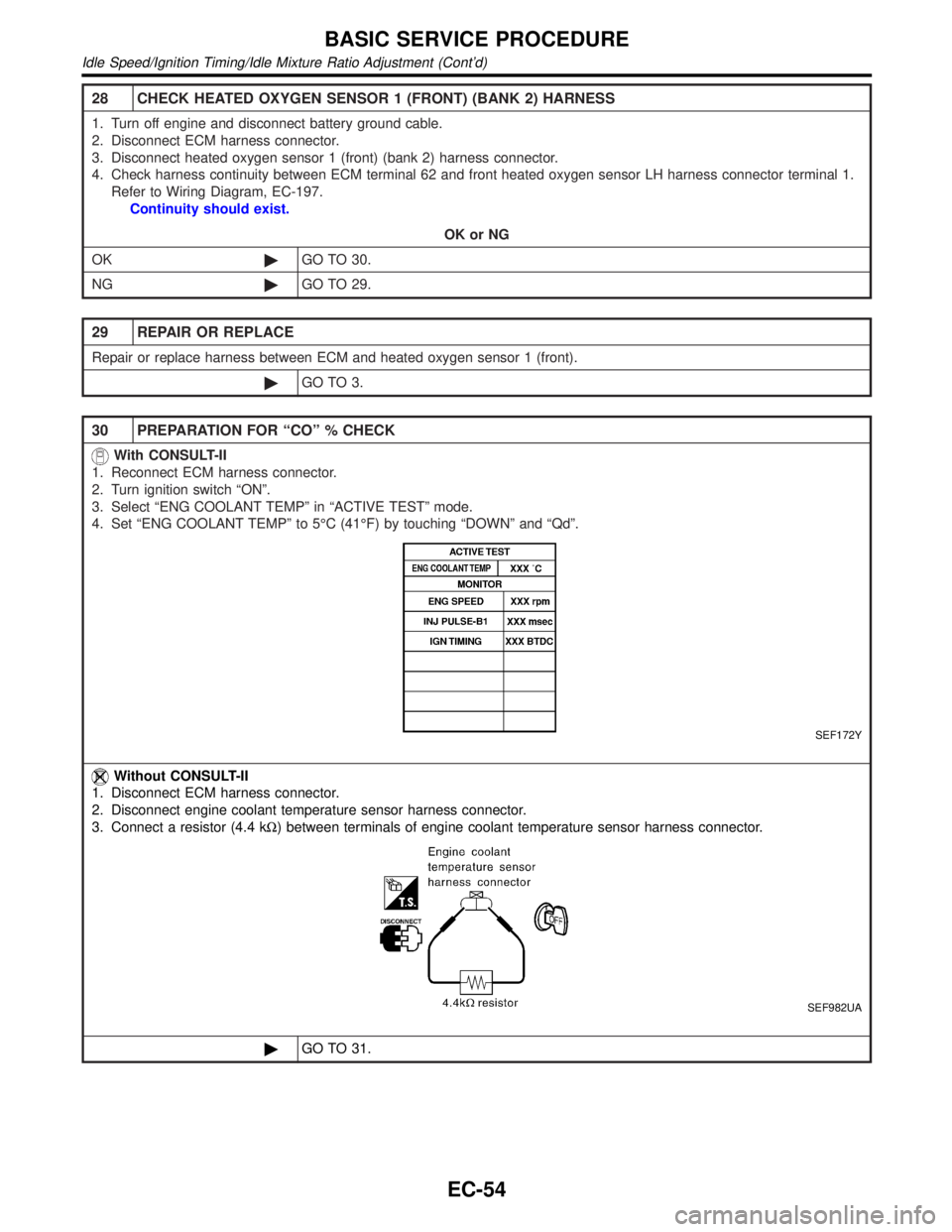
30 PREPARATION FOR ªCOº % CHECK
With CONSULT-II
1. Reconnect ECM harness connector.
2. Turn ignition switch ªONº.
3. Select ªENG COOLANT TEMPº in ªACTIVE TESTº mode.
4. Set ªENG COOLANT TEMPº to 5ÉC (41ÉF) by touching ªDOWNº and ªQdº.
SEF172Y
Without CONSULT-II
1. Disconnect ECM harness connector.
2. Disconnect engine coolant temperature sensor harness connector.
3. Connect a resistor (4.4 kW) between terminals of engine coolant temperature sensor harness connector.
SEF982UA
©GO TO 31.
BASIC SERVICE PROCEDURE
Idle Speed/Ignition Timing/Idle Mixture Ratio Adjustment (Cont'd)
EC-54
Page 592 of 2395

SEF452Y
Idle Air Volume LearningNBEC0642
SEF454Y
SEF455Y
DESCRIPTIONNBEC0642S01ªIdle Air Volume Learningº is an operation to learn the idle air vol-
ume that keeps each engine within the specific range. It must be
performed under any of the following conditions:
IEach time IACV-AAC valve, throttle body or ECM is replaced.
IIdle speed or ignition timing is out of specification.
PRE-CONDITIONINGNBEC0642S02Before performing ªIdle Air Volume Learningº, make sure that all of
the following conditions are satisfied.
Learning will be cancelled if any of the following conditions are
missed for even a moment.
IBattery voltage: More than 12.9V (At idle)
IEngine coolant temperature: 70 - 99ÉC (158 - 210ÉF)
IPNP switch: ON
IElectric load switch: OFF
(Air conditioner, headlamp, rear window defogger)
On vehicles equipped with daytime running light systems, if
the parking brake is applied before the engine is started the
headlamp will not illuminate.
ICooling fan motor: Not operating
ISteering wheel: Neutral (Straight-ahead position)
IVehicle speed: Stopped
ITransmission: Warmed-up
For A/T models with CONSULT-II, drive vehicle until ªFLUID
TEMP SEº in ªDATA MONITORº mode of ªA/Tº system indi-
cates less than 0.9V.
For A/T models without CONSULT-II, drive vehicle for 10 min-
utes.
OPERATION PROCEDURENBEC0642S03With CONSULT-IINBEC0642S03011. Turn ignition switch ªONº and wait at least 1 second.
2. Turn ignition switch ªOFFº and wait at least 10 seconds.
3. Start engine and warm it up to normal operating temperature.
4. Check that all items listed under the topic ªPRE-CONDITION-
INGº (previously mentioned) are in good order.
5. Turn ignition switch ªOFFº and wait at least 10 seconds.
6. Start the engine and let it idle for at least 30 seconds.
7. Select ªIDLE AIR VOL LEARNº in ªWORK SUPPORTº mode.
8. Touch ªSTARTº and wait 20 seconds.
9. Make sure that ªCMPLTº is displayed on CONSULT-II screen.
If ªINCMPº is displayed, ªIdle Air Volume Learningº will not be
carried out successfully. In this case, find the cause of the
problem by referring to the NOTE below.
10. Rev up the engine two or three times. Make sure that idle
speed and ignition timing are within specifications.
ITEM SPECIFICATION
Idle speed 750±50 rpm (in ªPº or ªNº position)
Ignition timing 15ɱ5É BTDC (in ªPº or ªNº position)
GI
MA
EM
LC
FE
AT
TF
PD
AX
SU
BR
ST
RS
BT
HA
SC
EL
IDX
BASIC SERVICE PROCEDURE
Idle Air Volume Learning
EC-57
Page 608 of 2395

SEF823YA
The emission related diagnostic information in the ECM can be erased by selecting ªERASEº in the ªSELF-
DIAG RESULTSº mode with CONSULT-II.
How to Erase DTC (With GST)NBEC0031S0602NOTE:
If the DTC is not for A/T related items (see EC-8), skip step 2.
1. If the ignition switch stays ªONº after repair work, be sure to turn ignition switch ªOFFº once. Wait at least
10 seconds and then turn it ªONº (engine stopped) again.
2. Perform ªSELF-DIAGNOSTIC PROCEDURE (Without CONSULT-II)º in AT section titled ªTROUBLE
DIAGNOSISº, ªSelf-diagnosisº. (The engine warm-up step can be skipped when performing the diagnosis
only to erase the DTC.)
3. Select Mode 4 with GST (Generic Scan Tool).
The emission related diagnostic information in the ECM can be erased by selecting Mode 4 with GST.
IIf the battery is disconnected, the emission-related diagnostic information will be lost after approx.
24 hours.
IThe following data are cleared when the ECM memory is erased.
1) Diagnostic trouble codes
2) 1st trip diagnostic trouble codes
3) Freeze frame data
4) 1st trip freeze frame data
5) System readiness test (SRT) codes
6) Test values
7) Others
GI
MA
EM
LC
FE
AT
TF
PD
AX
SU
BR
ST
RS
BT
HA
SC
EL
IDX
ON BOARD DIAGNOSTIC SYSTEM DESCRIPTION
Emission-related Diagnostic Information (Cont'd)
EC-73
Page 617 of 2395

ENGINE CONTROL COMPONENT PARTS/CONTROL
SYSTEMS APPLICATION
NBEC0034S02
ItemDIAGNOSTIC TEST MODE
WORK
SUP-
PORTSELF-DIAGNOSTIC
RESULTS
D ATA
MONI-
TORD ATA
MONI-
TOR
(SPEC)ACTIVE
TESTDTC & SRT
CONFIRMATION
DTC*1FREEZE
FRAME
DATA*2SRT
STATUSDTC
WORK
SUP-
PORT
ENGINE CONTROL COMPONENT PARTS
INPUT
Crankshaft position sensor
(POS)XXXX
Crankshaft position sensor (REF) X X X
Mass air flow sensor X X X
Engine coolant temperature sen-
sorXXXXX
Heated oxygen sensor 1 (front) X X X X X
Heated oxygen sensor 2 (rear) X X X X X
Vehicle speed sensorXXXX
Throttle position sensor X X X
Fuel tank temperature sensor X X X X
EVAP control system pressure
sensorXXX
Absolute pressure sensor X X X
Intake air temperature sensor X X X
Knock sensor X
Ignition switch (start signal) X X
Closed throttle position switch X X X
Closed throttle position switch
(throttle position sensor signal)XX
Air conditioner switch X X
Park/neutral position (PNP)
switchXXX
Power steering oil pressure
switchXX
Battery voltage X X
Ambient air temperature switch X X
Load signal X X
Swirl control valve control
vacuum check switchXXX
Fuel level sensor X X X
Intake valve timing control posi-
tion sensorXXX
ON BOARD DIAGNOSTIC SYSTEM DESCRIPTION
CONSULT-II (Cont'd)
EC-82
Page 620 of 2395

WORK SUPPORT MODE=NBEC0034S04
WORK ITEM CONDITION USAGE
TP SW/TP SEN IDLE POSI ADJIFOLLOW THE BASIC INSPECTION INSTRUCTION IN
THE SERVICE MANUAL.When adjusting the idle throttle
position
FUEL PRESSURE RELEASEIFUEL PUMP WILL STOP BY TOUCHING ªSTARTº
DURING IDLING.
CRANK A FEW TIMES AFTER ENGINE STALLS.When releasing fuel pressure
from fuel line
IDLE AIR VOL LEARNITHE IDLE AIR VOLUME THAT KEEPS THE ENGINE
WITHIN THE SPECIFIED RANGE IS MEMORIZED IN
ECM.When learning the idle air volume
SELF-LEARNING CONTITHE COEFFICIENT OF SELF-LEARNING CONTROL
MIXTURE RATIO RETURNS TO THE ORIGINAL
COEFFICIENT.When clearing the coefficient of
self-learning control valve
EVAP SYSTEM CLOSE OPEN THE VACUUM CUT VALVE BYPASS VALVE AND
CLOSE THE EVAP CANISTER VENT CONTROL VALVE
IN ORDER TO MAKE EVAP SYSTEM CLOSE UNDER
THE FOLLOWING CONDITIONS.
IIGN SW ªONº
IENGINE NOT RUNNING
IAMBIENT TEMPERATURE IS ABOVE 0ÉC (32ÉF).
INO VACUUM AND NO HIGH PRESSURE IN EVAP
SYSTEM
ITANK FUEL TEMP. IS MORE THAN 0ÉC (32ÉF).
IWITHIN 10 MINUTES AFTER STARTING ªEVAP SYS-
TEM CLOSEº
IWHEN TRYING TO EXECUTE ªEVAP SYSTEM
CLOSEº UNDER THE CONDITION EXCEPT ABOVE,
CONSULT-II WILL DISCONTINUE IT AND DISPLAY
APPROPRIATE INSTRUCTION.
NOTE:
WHEN STARTING ENGINE, CONSULT-II MAY DIS-
PLAY ªBATTERY VOLTAGE IS LOW. CHARGE
BATTERYº, EVEN IN USING CHARGED BATTERY.When detecting EVAP vapor leak
point of EVAP system
TARGET IGNITION TIMING ADJ*IIDLE CONDITIONIWhen adjusting target ignition
timing
After adjustment, confirm target
ignition timing with a timing
light.
IIf once the ªTARGET IDLE
RPM ADJº has been done, the
Idle Air Volume Learning proce-
dure will not be completed.
TARGET IDLE RPM ADJ*IIDLE CONDITION When setting target idle speed
*: This function is not necessary in the usual service procedure.
SELF-DIAGNOSTIC MODENBEC0034S05DTC and 1st Trip DTCNBEC0034S0501Regarding items of ªDTC and 1st trip DTCº, refer to ªTROUBLE
DIAGNOSIS Ð INDEXº (See EC-8.)
Freeze Frame Data and 1st Trip Freeze Frame DataNBEC0034S0502
Freeze frame data
item*1Description
DIAG TROUBLE
CODE
[PXXXX]IThe engine control component part/control system has a trouble code, it is displayed as ªPXXXXº.
(Refer to ªTROUBLE DIAGNOSIS Ð INDEXº, EC-8.)
GI
MA
EM
LC
FE
AT
TF
PD
AX
SU
BR
ST
RS
BT
HA
SC
EL
IDX
ON BOARD DIAGNOSTIC SYSTEM DESCRIPTION
CONSULT-II (Cont'd)
EC-85
Page 622 of 2395
![INFINITI QX4 2001 Factory Repair Manual DATA MONITOR MODE=NBEC0034S06
Monitored item [Unit]ECM
input
signalsMain
signalsDescription Remarks
ENG SPEED [rpm]qqIIndicates the engine speed computed
from the REF signal (120É signal) of the
cran INFINITI QX4 2001 Factory Repair Manual DATA MONITOR MODE=NBEC0034S06
Monitored item [Unit]ECM
input
signalsMain
signalsDescription Remarks
ENG SPEED [rpm]qqIIndicates the engine speed computed
from the REF signal (120É signal) of the
cran](/img/42/57027/w960_57027-621.png)
DATA MONITOR MODE=NBEC0034S06
Monitored item [Unit]ECM
input
signalsMain
signalsDescription Remarks
ENG SPEED [rpm]qqIIndicates the engine speed computed
from the REF signal (120É signal) of the
crankshaft position sensor (REF).
CKPS´RPM (POS)
[rpm]qIIndicates the engine speed computed
from the POS signal (1É signal) of the
crankshaft position sensor (POS).IAccuracy becomes poor if engine
speed drops below the idle rpm.
IIf the signal is interrupted while the
engine is running, an abnormal value
may be indicated.
POS COUNTqIIndicates the number of signal plate
(Flywheel/Drive Plate) cogs (tooth) dur-
ing one revolution of the engine.
MAS A/F SE-B1 [V]qqIThe signal voltage of the mass air flow
sensor is displayed.IWhen the engine is stopped, a certain
value is indicated.
COOLAN TEMP/S
[ÉC] or [ÉF]qqIThe engine coolant temperature (deter-
mined by the signal voltage of the
engine coolant temperature sensor) is
displayed.IWhen the engine coolant temperature
sensor is open or short-circuited, ECM
enters fail-safe mode. The engine cool-
ant temperature determined by the
ECM is displayed.
HO2S1 (B1) [V]qq
IThe signal voltage of the front heated
oxygen sensor is displayed.
HO2S1 (B2) [V]qq
HO2S2 (B1) [V]qq
IThe signal voltage of the rear heated
oxygen sensor is displayed.
HO2S2 (B2) [V]qq
HO2S1 MNTR (B1)
[RICH/LEAN]qIDisplay of front heated oxygen sensor
signal during air-fuel ratio feedback
control:
RICH ... means the mixture became
ªrichº, and control is being affected
toward a leaner mixture.
LEAN ... means the mixture became
ªleanº, and control is being affected
toward a rich mixture.IAfter turning ON the ignition switch,
ªRICHº is displayed until air-fuel mixture
ratio feedback control begins.
IWhen the air-fuel ratio feedback is
clamped, the value just before the
clamping is displayed continuously. HO2S1 MNTR (B2)
[RICH/LEAN]q
HO2S2 MNTR (B1)
[RICH/LEAN]qIDisplay of rear heated oxygen sensor
signal:
RICH ... means the amount of oxygen
after three way catalyst is relatively
small.
LEAN ... means the amount of oxygen
after three way catalyst is relatively
large.IWhen the engine is stopped, a certain
value is indicated.
HO2S2 MNTR (B2)
[RICH/LEAN]q
VHCL SPEED SE
[km/h] or [mph]qqIThe vehicle speed computed from the
vehicle speed sensor signal is dis-
played.
BATTERY VOLT [V]qqIThe power supply voltage of ECM is
displayed.
THRTL POS SEN [V]qqIThe throttle position sensor signal volt-
age is displayed.
FUEL T/TMP SE
[ÉC] or [ÉF]IThe fuel temperature judged from the
tank fuel temperature sensor signal
voltage is displayed.GI
MA
EM
LC
FE
AT
TF
PD
AX
SU
BR
ST
RS
BT
HA
SC
EL
IDX
ON BOARD DIAGNOSTIC SYSTEM DESCRIPTION
CONSULT-II (Cont'd)
EC-87
Page 631 of 2395

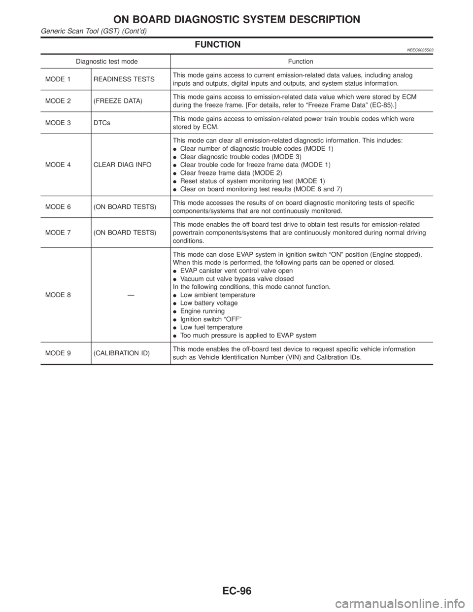
FUNCTIONNBEC0035S03
Diagnostic test mode Function
MODE 1 READINESS TESTSThis mode gains access to current emission-related data values, including analog
inputs and outputs, digital inputs and outputs, and system status information.
MODE 2 (FREEZE DATA)This mode gains access to emission-related data value which were stored by ECM
during the freeze frame. [For details, refer to ªFreeze Frame Dataº (EC-85).]
MODE 3 DTCsThis mode gains access to emission-related power train trouble codes which were
stored by ECM.
MODE 4 CLEAR DIAG INFOThis mode can clear all emission-related diagnostic information. This includes:
IClear number of diagnostic trouble codes (MODE 1)
IClear diagnostic trouble codes (MODE 3)
IClear trouble code for freeze frame data (MODE 1)
IClear freeze frame data (MODE 2)
IReset status of system monitoring test (MODE 1)
IClear on board monitoring test results (MODE 6 and 7)
MODE 6 (ON BOARD TESTS)This mode accesses the results of on board diagnostic monitoring tests of specific
components/systems that are not continuously monitored.
MODE 7 (ON BOARD TESTS)This mode enables the off board test drive to obtain test results for emission-related
powertrain components/systems that are continuously monitored during normal driving
conditions.
MODE 8 ÐThis mode can close EVAP system in ignition switch ªONº position (Engine stopped).
When this mode is performed, the following parts can be opened or closed.
IEVAP canister vent control valve open
IVacuum cut valve bypass valve closed
In the following conditions, this mode cannot function.
ILow ambient temperature
ILow battery voltage
IEngine running
IIgnition switch ªOFFº
ILow fuel temperature
IToo much pressure is applied to EVAP system
MODE 9 (CALIBRATION ID)This mode enables the off-board test device to request specific vehicle information
such as Vehicle Identification Number (VIN) and Calibration IDs.
ON BOARD DIAGNOSTIC SYSTEM DESCRIPTION
Generic Scan Tool (GST) (Cont'd)
EC-96