Battery INFINITI QX4 2001 Factory Workshop Manual
[x] Cancel search | Manufacturer: INFINITI, Model Year: 2001, Model line: QX4, Model: INFINITI QX4 2001Pages: 2395, PDF Size: 43.2 MB
Page 465 of 2395
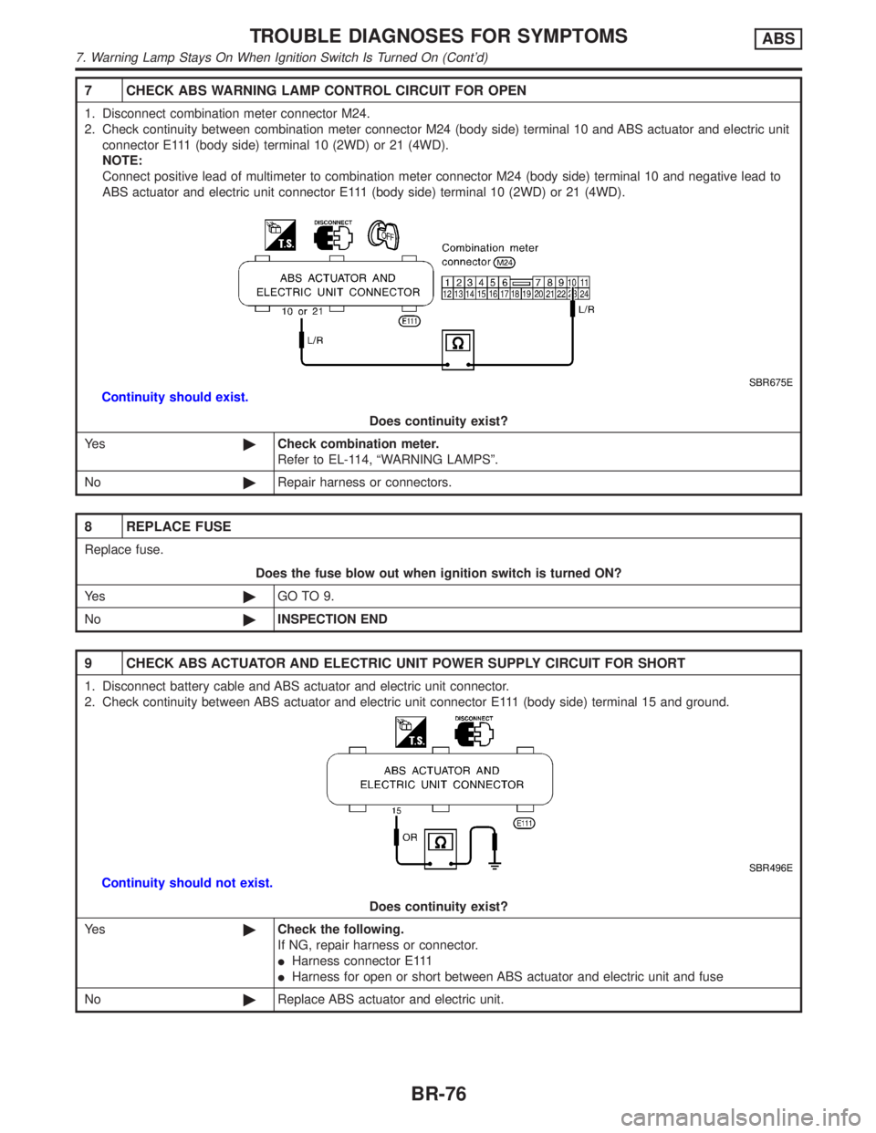
7 CHECK ABS WARNING LAMP CONTROL CIRCUIT FOR OPEN
1. Disconnect combination meter connector M24.
2. Check continuity between combination meter connector M24 (body side) terminal 10 and ABS actuator and electric unit
connector E111 (body side) terminal 10 (2WD) or 21 (4WD).
NOTE:
Connect positive lead of multimeter to combination meter connector M24 (body side) terminal 10 and negative lead to
ABS actuator and electric unit connector E111 (body side) terminal 10 (2WD) or 21 (4WD).
SBR675E
Continuity should exist.
Does continuity exist?
Ye s©Check combination meter.
Refer to EL-114, ªWARNING LAMPSº.
No©Repair harness or connectors.
8 REPLACE FUSE
Replace fuse.
Does the fuse blow out when ignition switch is turned ON?
Ye s©GO TO 9.
No©INSPECTION END
9 CHECK ABS ACTUATOR AND ELECTRIC UNIT POWER SUPPLY CIRCUIT FOR SHORT
1. Disconnect battery cable and ABS actuator and electric unit connector.
2. Check continuity between ABS actuator and electric unit connector E111 (body side) terminal 15 and ground.
SBR496E
Continuity should not exist.
Does continuity exist?
Ye s©Check the following.
If NG, repair harness or connector.
IHarness connector E111
IHarness for open or short between ABS actuator and electric unit and fuse
No©Replace ABS actuator and electric unit.
TROUBLE DIAGNOSES FOR SYMPTOMSABS
7. Warning Lamp Stays On When Ignition Switch Is Turned On (Cont'd)
BR-76
Page 471 of 2395
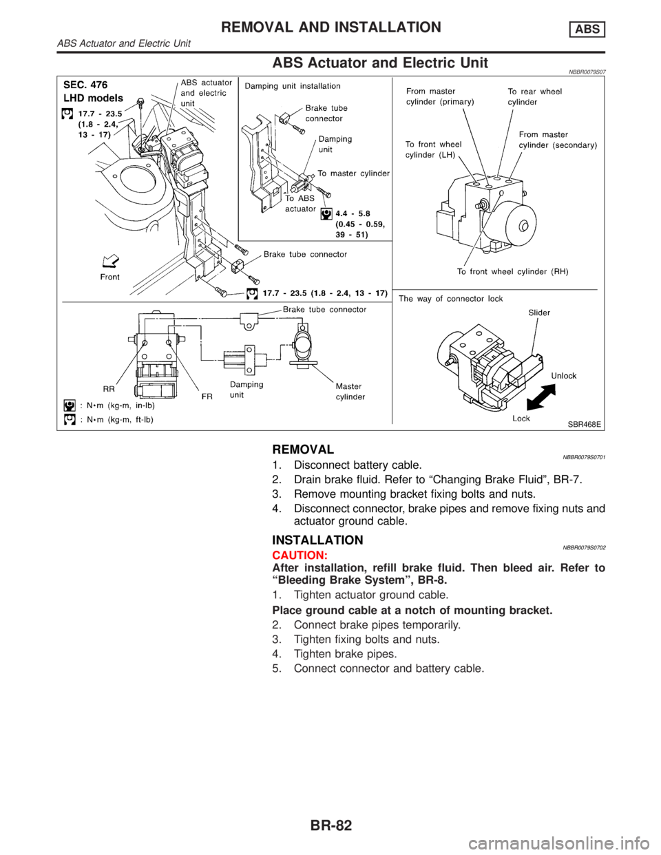
ABS Actuator and Electric UnitNBBR0079S07
SBR468E
REMOVALNBBR0079S07011. Disconnect battery cable.
2. Drain brake fluid. Refer to ªChanging Brake Fluidº, BR-7.
3. Remove mounting bracket fixing bolts and nuts.
4. Disconnect connector, brake pipes and remove fixing nuts and
actuator ground cable.
INSTALLATIONNBBR0079S0702CAUTION:
After installation, refill brake fluid. Then bleed air. Refer to
ªBleeding Brake Systemº, BR-8.
1. Tighten actuator ground cable.
Place ground cable at a notch of mounting bracket.
2. Connect brake pipes temporarily.
3. Tighten fixing bolts and nuts.
4. Tighten brake pipes.
5. Connect connector and battery cable.
REMOVAL AND INSTALLATIONABS
ABS Actuator and Electric Unit
BR-82
Page 494 of 2395

Removal and InstallationNBBT0008CAUTION:
IDisconnect both battery cables in advance.
IDisconnect air bag system line in advance.
INever tamper with or force air bag lid open, as this may
adversely affect air bag performance.
IBe careful not to scratch pad and other parts.
SBT042A
*1 RS-17 *2 BT-28
GI
MA
EM
LC
EC
FE
AT
TF
PD
AX
SU
BR
ST
RS
HA
SC
EL
IDX
INSTRUMENT PANEL ASSEMBLY
Removal and Installation
BT-21
Page 514 of 2395

Removal and InstallationNBBT0014IWhen removing or installing the seat trim, carefully handle it to keep dirt out and avoid damage.
HFor Wiring Diagram, refer to EL-181, ªPOWER SEATº for details.
CAUTION:
IBefore removing the front seat, turn the ignition switch off, disconnect both battery cables and wait
at least 3 minutes.
IWhen checking the power seat circuit for continuity using a circuit tester, do not confuse its con-
nector with the side air bag module connector. Such an error may cause the air bag to deploy.
IDo not drop, tilt, or bump the side air bag module installed in the seat. Always handle it with care.
SBT066A
SBT067A
GI
MA
EM
LC
EC
FE
AT
TF
PD
AX
SU
BR
ST
RS
HA
SC
EL
IDX
FRONT SEAT
Removal and Installation
BT-41
Page 549 of 2395
Supplemental Restraint System (SRS) ªAIR
BAGº and ªSEAT BELT PRE-TENSIONERº
NBEC0002The Supplemental Restraint System such as ªAIR BAGº and ªSEAT BELT PRE-TENSIONERº used along with
a seat belt, helps to reduce the risk or severity of injury to the driver and front passenger for certain types of
collision. The SRS system composition which is available to INFINITI QX4 is as follows:
IFor a frontal collision
The Supplemental Restraint System consists of driver air bag module (located in the center of the steer-
ing wheel), front passenger air bag module (located on the instrument panel on passenger side), seat belt
pre-tensioners, a diagnosis sensor unit, warning lamp, wiring harness and spiral cable.
IFor a side collision
The Supplemental Restraint System consists of front side air bag module (located in the outer side of front
seat), satellite sensor, diagnosis sensor unit (one of components of air bags for a frontal collision), wiring
harness, warning lamp (one of components of air bags for a frontal collision).
Information necessary to service the system safely is included in theRS sectionof this Service Manual.
WARNING:
ITo avoid rendering the SRS inoperative, which could increase the risk of personal injury or death
in the event of a collision which would result in air bag inflation, all maintenance must be performed
by an authorized INFINITI dealer.
IImproper maintenance, including incorrect removal and installation of the SRS, can lead to per-
sonal injury caused by unintentional activation of the system. For removal of Spiral Cable and Air
Bag Module, see the RS section.
IDo not use electrical test equipment on any circuit related to the SRS unless instructed to in this
Service Manual. Spiral cable and wiring harnesses covered with yellow insulation tape either just
before the harness connectors or for the complete harness are related to the SRS.
Precautions for On Board Diagnostic (OBD)
System of Engine and A/T
NBEC0003The ECM has an on board diagnostic system. It will light up the malfunction indicator lamp (MIL) to warn the
driver of a malfunction causing emission deterioration.
CAUTION:
IBe sure to turn the ignition switch OFF and disconnect the negative battery terminal before any
repair or inspection work. The open/short circuit of related switches, sensors, solenoid valves, etc.
will cause the MIL to light up.
IBe sure to connect and lock the connectors securely after work. A loose (unlocked) connector will
cause the MIL to light up due to the open circuit. (Be sure the connector is free from water, grease,
dirt, bent terminals, etc.)
ICertain systems and components, especially those related to OBD, may use a new style slide-
locking type harness connector. For description and how to disconnect, refer to EL-6, ªHARNESS
CONNECTOR (SLIDE-LOCKING TYPE)º.
IBe sure to route and secure the harnesses properly after work. The interference of the harness with
a bracket, etc. may cause the MIL to light up due to the short circuit.
IBe sure to connect rubber tubes properly after work. A misconnected or disconnected rubber tube
may cause the MIL to light up due to the malfunction of the fuel injection system, etc.
IBe sure to erase the unnecessary malfunction information (repairs completed) from the ECM and
TCM (Transmission control module) before returning the vehicle to the customer.
PRECAUTIONS
Supplemental Restraint System (SRS) ªAIR BAGº and ªSEAT BELT PRE-TENSIONERº
EC-14
Page 551 of 2395

SEF289H
PrecautionsNBEC0005IBefore connecting or disconnecting the ECM harness
connector, turn ignition switch OFF and disconnect nega-
tive battery terminal. Failure to do so may damage the
ECM because battery voltage is applied to ECM even if
ignition switch is turned off.
SEF908W
IWhen connecting ECM harness connector, fasten it
securely with a lever as far as it will go as shown at left.
SEF291H
IWhen connecting or disconnecting pin connectors into or
from ECM, take care not to damage pin terminals (bend or
break).
Make sure that there are not any bends or breaks on ECM
pin terminal, when connecting pin connectors.
MEF040D
IBefore replacing ECM, perform ªECM Terminals and Ref-
erence Valueº inspection and make sure ECM functions
properly. Refer to EC-127.
SEF217U
IAfter performing each TROUBLE DIAGNOSIS, perform
ªDTC Confirmation Procedureº or ªOverall Function
Checkº.
The DTC should not be displayed in the ªDTC Confirma-
tion Procedureº if the repair is completed. The ªOverall
Function Checkº should be a good result if the repair is
completed.
PRECAUTIONS
Precautions
EC-16
Page 562 of 2395
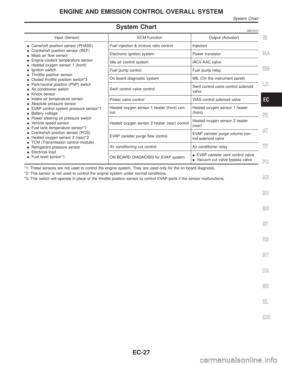
System ChartNBEC0013
Input (Sensor) ECM Function Output (Actuator)
ICamshaft position sensor (PHASE)
ICrankshaft position sensor (REF)
IMass air flow sensor
IEngine coolant temperature sensor
IHeated oxygen sensor 1 (front)
IIgnition switch
IThrottle position sensor
IClosed throttle position switch*3
IPark/neutral position (PNP) switch
IAir conditioner switch
IKnock sensor
IIntake air temperature sensor
IAbsolute pressure sensor
IEVAP control system pressure sensor*1
IBattery voltage
IPower steering oil pressure switch
IVehicle speed sensor
IFuel tank temperature sensor*1
ICrankshaft position sensor (POS)
IHeated oxygen sensor 2 (rear)*2
ITCM (Transmission control module)
IRefrigerant pressure sensor
IElectrical load
IFuel level sensor*1Fuel injection & mixture ratio control Injectors
Electronic ignition system Power transistor
Idle air control system IACV-AAC valve
Fuel pump control Fuel pump relay
On board diagnostic system MIL (On the instrument panel)
Swirl control valve controlSwirl control valve control solenoid
valve
Power valve control VIAS control solenoid valve
Heated oxygen sensor 1 heater (front) con-
trolHeated oxygen sensor 1 heater
(front)
Heated oxygen sensor 2 heater (rear) controlHeated oxygen sensor 2 heater
(rear)
EVAP canister purge flow controlEVAP canister purge volume con-
trol solenoid valve
Air conditioning cut control Air conditioner relay
ON BOARD DIAGNOSIS for EVAP systemIEVAP canister vent control valve
IVacuum cut valve bypass valve
*1: These sensors are not used to control the engine system. They are used only for the on board diagnosis.
*2: This sensor is not used to control the engine system under normal conditions.
*3: This switch will operate in place of the throttle position sensor to control EVAP parts if the sensor malfunctions.GI
MA
EM
LC
FE
AT
TF
PD
AX
SU
BR
ST
RS
BT
HA
SC
EL
IDX
ENGINE AND EMISSION CONTROL OVERALL SYSTEM
System Chart
EC-27
Page 563 of 2395
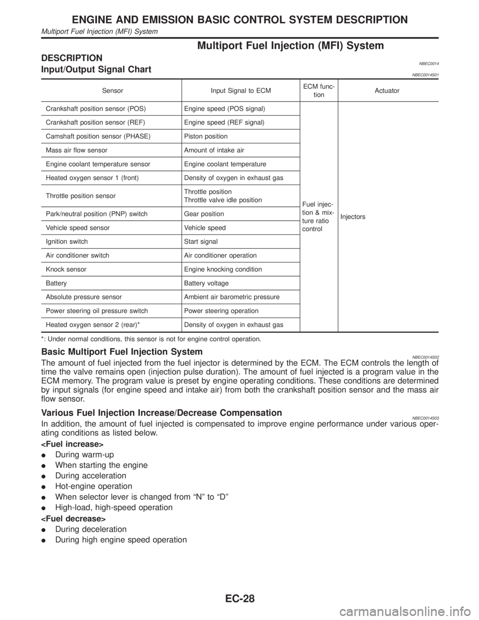
Multiport Fuel Injection (MFI) System
DESCRIPTIONNBEC0014Input/Output Signal ChartNBEC0014S01
Sensor Input Signal to ECMECM func-
tionActuator
Crankshaft position sensor (POS) Engine speed (POS signal)
Fuel injec-
tion & mix-
ture ratio
controlInjectors Crankshaft position sensor (REF) Engine speed (REF signal)
Camshaft position sensor (PHASE) Piston position
Mass air flow sensor Amount of intake air
Engine coolant temperature sensor Engine coolant temperature
Heated oxygen sensor 1 (front) Density of oxygen in exhaust gas
Throttle position sensorThrottle position
Throttle valve idle position
Park/neutral position (PNP) switch Gear position
Vehicle speed sensor Vehicle speed
Ignition switch Start signal
Air conditioner switch Air conditioner operation
Knock sensor Engine knocking condition
Battery Battery voltage
Absolute pressure sensor Ambient air barometric pressure
Power steering oil pressure switch Power steering operation
Heated oxygen sensor 2 (rear)* Density of oxygen in exhaust gas
*: Under normal conditions, this sensor is not for engine control operation.
Basic Multiport Fuel Injection SystemNBEC0014S02The amount of fuel injected from the fuel injector is determined by the ECM. The ECM controls the length of
time the valve remains open (injection pulse duration). The amount of fuel injected is a program value in the
ECM memory. The program value is preset by engine operating conditions. These conditions are determined
by input signals (for engine speed and intake air) from both the crankshaft position sensor and the mass air
flow sensor.
Various Fuel Injection Increase/Decrease CompensationNBEC0014S03In addition, the amount of fuel injected is compensated to improve engine performance under various oper-
ating conditions as listed below.
IDuring warm-up
IWhen starting the engine
IDuring acceleration
IHot-engine operation
IWhen selector lever is changed from ªNº to ªDº
IHigh-load, high-speed operation
IDuring deceleration
IDuring high engine speed operation
ENGINE AND EMISSION BASIC CONTROL SYSTEM DESCRIPTION
Multiport Fuel Injection (MFI) System
EC-28
Page 565 of 2395
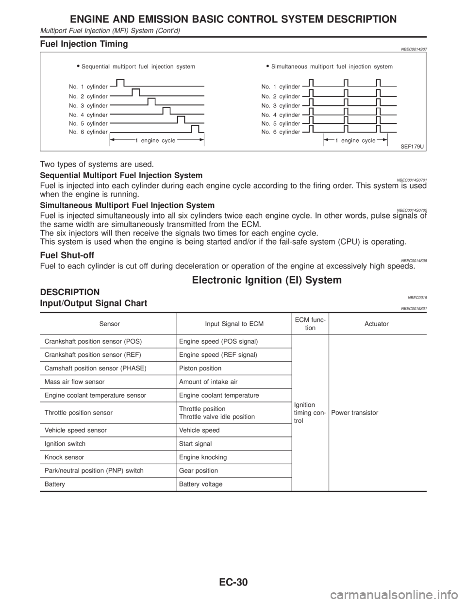
Fuel Injection TimingNBEC0014S07
SEF179U
Two types of systems are used.
Sequential Multiport Fuel Injection System
NBEC0014S0701Fuel is injected into each cylinder during each engine cycle according to the firing order. This system is used
when the engine is running.
Simultaneous Multiport Fuel Injection System
NBEC0014S0702Fuel is injected simultaneously into all six cylinders twice each engine cycle. In other words, pulse signals of
the same width are simultaneously transmitted from the ECM.
The six injectors will then receive the signals two times for each engine cycle.
This system is used when the engine is being started and/or if the fail-safe system (CPU) is operating.
Fuel Shut-offNBEC0014S08Fuel to each cylinder is cut off during deceleration or operation of the engine at excessively high speeds.
Electronic Ignition (EI) System
DESCRIPTIONNBEC0015Input/Output Signal ChartNBEC0015S01
Sensor Input Signal to ECMECM func-
tionActuator
Crankshaft position sensor (POS) Engine speed (POS signal)
Ignition
timing con-
trolPower transistor Crankshaft position sensor (REF) Engine speed (REF signal)
Camshaft position sensor (PHASE) Piston position
Mass air flow sensor Amount of intake air
Engine coolant temperature sensor Engine coolant temperature
Throttle position sensorThrottle position
Throttle valve idle position
Vehicle speed sensor Vehicle speed
Ignition switch Start signal
Knock sensor Engine knocking
Park/neutral position (PNP) switch Gear position
Battery Battery voltage
ENGINE AND EMISSION BASIC CONTROL SYSTEM DESCRIPTION
Multiport Fuel Injection (MFI) System (Cont'd)
EC-30
Page 566 of 2395
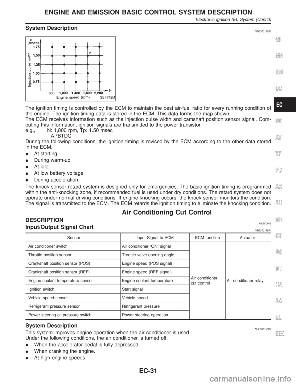
System DescriptionNBEC0015S02
SEF742M
The ignition timing is controlled by the ECM to maintain the best air-fuel ratio for every running condition of
the engine. The ignition timing data is stored in the ECM. This data forms the map shown.
The ECM receives information such as the injection pulse width and camshaft position sensor signal. Com-
puting this information, ignition signals are transmitted to the power transistor.
e.g., N: 1,800 rpm, Tp: 1.50 msec
A ÉBTDC
During the following conditions, the ignition timing is revised by the ECM according to the other data stored
in the ECM.
IAt starting
IDuring warm-up
IAt idle
IAt low battery voltage
IDuring acceleration
The knock sensor retard system is designed only for emergencies. The basic ignition timing is programmed
within the anti-knocking zone, if recommended fuel is used under dry conditions. The retard system does not
operate under normal driving conditions. If engine knocking occurs, the knock sensor monitors the condition.
The signal is transmitted to the ECM. The ECM retards the ignition timing to eliminate the knocking condition.
Air Conditioning Cut Control
DESCRIPTIONNBEC0016Input/Output Signal ChartNBEC0016S01
Sensor Input Signal to ECM ECM function Actuator
Air conditioner switch Air conditioner ªONº signal
Air conditioner
cut controlAir conditioner relay Throttle position sensor Throttle valve opening angle
Crankshaft position sensor (POS) Engine speed (POS signal)
Crankshaft position sensor (REF) Engine speed (REF signal)
Engine coolant temperature sensor Engine coolant temperature
Ignition switch Start signal
Vehicle speed sensor Vehicle speed
Refrigerant pressure sensor Refrigerant pressure
Power steering oil pressure switch Power steering operation
System DescriptionNBEC0016S02This system improves engine operation when the air conditioner is used.
Under the following conditions, the air conditioner is turned off.
IWhen the accelerator pedal is fully depressed.
IWhen cranking the engine.
IAt high engine speeds.
GI
MA
EM
LC
FE
AT
TF
PD
AX
SU
BR
ST
RS
BT
HA
SC
EL
IDX
ENGINE AND EMISSION BASIC CONTROL SYSTEM DESCRIPTION
Electronic Ignition (EI) System (Cont'd)
EC-31