elec INFINITI QX4 2001 Factory Service Manual
[x] Cancel search | Manufacturer: INFINITI, Model Year: 2001, Model line: QX4, Model: INFINITI QX4 2001Pages: 2395, PDF Size: 43.2 MB
Page 2158 of 2395

Trouble Diagnoses with
Battery/Starting/Charging System Tester
NBSC0018CAUTION:
When working with batteries, always wear appropriate eye
protection.
NOTE:
ITo ensure a complete and thorough diagnosis, the battery,
starter and alternator test segments must be done as a set
from start to finish.
IIf battery surface charge is detected while testing, the tester
will prompt you to turn on the headlights to remove the surface
charge.
IIf necessary, the tester will prompt you to determine if the bat-
tery temperature is above or below 0ÉC (32ÉF). Choose the
appropriate selection by pressing the up or down arrow button,
then press ªENTERº to make the selection.
SEL404X
1. Turn off all loads on the vehicle electrical system. Clean or
repair as necessary.
2. Visually inspect the battery, battery terminals and cable ends
with ignition switch in ªOFFº position.
NOTE:
The contact surface between the battery terminals, cable ends and
tester leads must be clean for a valid test. A poor connection will
prevent testing and a ªCHECK CONNECTIONº message will
appear during the test procedures. If this occurs, clean the battery
post and terminals, reconnect them and restart the test.
3. Connect the red tester lead clamp to the positive battery
terminal, and the black to the negative terminal.
SEL405X
4. The tester will turn on automatically. Using the arrow keys,
select ªIN VEHICLEº on the tester and then press the ªENTERº
key.
GI
MA
EM
LC
EC
FE
AT
TF
PD
AX
SU
BR
ST
RS
BT
HA
EL
IDX
BATTERY
Trouble Diagnoses with Battery/Starting/Charging System Tester
SC-7
Page 2159 of 2395

SEL406X
5. Locate the battery type and rating stamped or written on the
top case of the battery to be tested.
NOTE:
The battery type and rating will have either of the following.
CCA: Cold Cranking Amps (490 CCA, 550 CCA, etc.)
JIS: Japanese Industrial Standard.
Battery is stamped with a number such as:
80D26L: 80 (rank of output), D (physical size-depth), 26 (width
in cm). The last character L (post configuration) is not input into
the tester.
The tester requires the rating for the battery be entered exactly
as it is written or stamped on the battery. Do not attempt a CCA
conversion for JIS stamped batteries. JIS must be input
directly.
6. Using the arrow and ªENTERº keys alternately, select the bat-
tery type and rating.
NOTE:
The tester lists five choices; CCA, JIS, IEC, DIN, and EN. Only use
CCA or JIS.
SEL407X
7. Press ªENTERº to begin the test. Diagnosis results are dis-
played on the tester. Refer to ªDIAGNOSTIC RESULT ITEM
CHARTº SC-9.
SEL576X
8. Press ªENTERº, then test output code is displayed. Record the
test output code on the repair order.
9. Toggle back to the ªDIAGNOSTIC SCREENº for test results.
NOTE:
IIf necessary, the tester will ask the user to determine if the
battery has just been charged. Choose the appropriate selec-
tion by pressing the up or down arrow button and then press
the ªENTERº button to make the selection.
IWhen testing a battery installed in a vehicle that has recently
been driven, select ªBEFORE CHANGEº.
IIf the battery has just been slow charged due to a ªCHARGE
& RETESTº decision by the tester, and the tester asks the user
ªBEFORE CHARGE/AFTER CHARGEº, select ªAFTER
CHARGEº.
BATTERY
Trouble Diagnoses with Battery/Starting/Charging System Tester (Cont'd)
SC-8
Page 2160 of 2395

DIAGNOSTIC RESULT ITEM CHARTNBSC0018S01
Diagnostic item Service procedure
GOOD BATTERY Battery is OK, go to ªTrouble Diagnosesº, ªSTARTING SYSTEMº. Refer to SC-12.
REPLACE BATTERYReplace battery.
Before replacing battery, clean the battery cable clamps and battery posts. Perform bat-
tery test again with Battery/Starting/Charging system tester. If second test result is
ªReplace Batteryº, then do so. Perform battery test again to confirm repair.
BAD CELL-REPLACEReplace the battery. Perform battery test again with Battery/Starting/Charging system
tester to confirm repair.
GOOD-RECHARGEPerform the slow battery charging procedure. (Initial rate of charge is 10A for 12 hours.)
Perform battery test again with Battery/Starting/Charging system tester.
CHARGE & RETESTPerform the slow battery charging. (Initial rate of charge is 10A for 12 hours.)
Perform battery test again with Battery/Starting/Charging system tester to confirm repair.
NOTE:
If the tester asks the user ªBEFORE CHARGE/AFTER CHARGEº, select ªAFTER
CHARGEº.GI
MA
EM
LC
EC
FE
AT
TF
PD
AX
SU
BR
ST
RS
BT
HA
EL
IDX
BATTERY
Trouble Diagnoses with Battery/Starting/Charging System Tester (Cont'd)
SC-9
Page 2161 of 2395

System DescriptionNBSC0004Power is supplied at all times
Ito ignition switch terminal 1
Ithrough 40A fusible link (lettere, located in the fuse and fusible link box).
With the ignition switch in the ON or START position, power is supplied through 10A fuse [No. 18, located in
the fuse block (J/B)].
Ito park/neutral position relay terminal 1.
Also, with the ignition switch in the START position, power is supplied
Ifrom ignition switch terminal 5
Ito park/neutral position relay terminal 6.
With the selector lever in the P or N position, ground is supplied
Ito park/neutral position relay terminal 2 through the park/neutral position switch.
Then park/neutral position relay is energized and power is supplied
Ifrom park/neutral position relay terminal 7
Ito terminal 2 of the starter motor windings.
The starter motor plunger closes and provides a closed circuit between the battery and starter motor. The
starter motor is grounded to the engine block. With power and ground supplied, cranking occurs and the engine
starts.
STARTING SYSTEM
System Description
SC-10
Page 2163 of 2395

Trouble Diagnoses with
Battery/Starting/Charging System Tester
NBSC0019NOTE:
To ensure a complete and thorough diagnosis, the battery, starter
and alternator test segments must be done as a set from start to
finish.
SEL408X
1. Turn off all loads on the vehicle electrical system.
2. Perform battery test with Battery/Starting/Charging system
tester. Refer to SC-7.
3. Press ªENTERº to begin the starting system test.
SEL409X
4. Start the engine.
SEL410X
5. Diagnosis result is displayed on the tester. Refer to ªDIAG-
NOSTIC RESULT ITEM CHARTº, SC-13.
NOTE:
IIf the starter performs normally but the engine does not start,
perform engine diagnosis.
IFor intermittent ªNO CRANKº or ªNO STARTER OPERATIONº
incidents, go to DIAGNOSTIC PROCEDURE 2.
STARTING SYSTEM
Trouble Diagnoses with Battery/Starting/Charging System Tester
SC-12
Page 2170 of 2395

System DescriptionNBSC0009The alternator provides DC voltage to operate the vehicle's electrical system and to keep the battery charged.
The voltage output is controlled by the IC regulator.
Power is supplied at all times to alternator terminal S through:
I120A fusible link (lettera, located in the fuse and fusible link box), and
I7.5A fuse (No. 65, located in the fuse and fusible link box).
Terminal B supplies power to charge the battery and operate the vehicle's electrical system. Output voltage
is controlled by the IC regulator at terminal S detecting the input voltage. The charging circuit is protected by
the 120A fusible link.
Terminal E of the alternator supplies ground through body ground E101.
With the ignition switch in the ON or START position, power is supplied
Ithrough 10A fuse [No. 8, located in the fuse block (J/B)]
Ito combination meter terminal 12 for the charge warning lamp.
Ground is supplied to terminal 43 of the combination meter through terminal L of the alternator. With power
and ground supplied, the charge warning lamp will illuminate. When the alternator is providing sufficient volt-
age with the engine running, the ground is opened and the charge warning lamp will go off.
If the charge warning lamp illuminates with the engine running, a fault is indicated.GI
MA
EM
LC
EC
FE
AT
TF
PD
AX
SU
BR
ST
RS
BT
HA
EL
IDX
CHARGING SYSTEM
System Description
SC-19
Page 2172 of 2395

Trouble Diagnoses with
Battery/Starting/Charging System Tester
NBSC0020NOTE:
To ensure a complete and thorough diagnosis, the battery, starter
and alternator test segments must be done as a set from start to
finish.
SEL417X
1. Turn off all loads on the vehicle electrical system.
2. Perform battery and starting system test with Battery/Starting/
Charging system tester.
3. Press ªENTERº to begin the charging system test.
4. Start engine.
SEL418X
5. Press ªENTERº until ªLOADS OFF REV ENGINE 5 SECº is
displayed.
6. Raise and hold the engine speed at 1,500 to 2,000 rpm for
about 5 seconds, then return to the engine to idle.
Once the increase in engine rpm is detected, press ªENTERº
to continue.
NOTE:
IIf after 30 seconds an increase in engine idle speed is not
detected, ªRPM NOT DETECTEDº will display.
ISome engines may have a higher idle initially after starting,
particularly when the engine is cold. The tester may detect this
without any other action being taken. If this occurs, continue on
with the testing process. The final results will not be affected.
SEL419X
7. The tester now checks the engine at idle and performs the
DIODE/RIPPLE check.
8. When complete, the tester will prompt you to turn on the fol-
lowing electrical loads.
IHeater fun set to highest. Do not run the A/C or windshield
defroster.
IHeadlamp high beam
IRear window defogger
NOTE:
Do not run the windshield wipers or any other cyclical loads.
GI
MA
EM
LC
EC
FE
AT
TF
PD
AX
SU
BR
ST
RS
BT
HA
EL
IDX
CHARGING SYSTEM
Trouble Diagnoses with Battery/Starting/Charging System Tester
SC-21
Page 2183 of 2395

Supplemental Restraint System (SRS) ªAIR
BAGº and ªSEAT BELT PRE-TENSIONERº
NBST0044The Supplemental Restraint System such as ªAIR BAGº and ªSEAT BELT PRE-TENSIONERº used along with
a seat belt, helps to reduce the risk or severity of injury to the driver and front passenger for certain types of
collision. The SRS system composition which is available to INFINITI QX4 is as follows:
IFor a frontal collision
The Supplemental Restraint System consists of driver air bag module (located in the center of the steer-
ing wheel), front passenger air bag module (located on the instrument panel on passenger side), seat belt
pre-tensioners, a diagnosis sensor unit, warning lamp, wiring harness and spiral cable.
IFor a side collision
The Supplemental Restraint System consists of side air bag module (located in the outer side of front seat),
satellite sensor, diagnosis sensor unit (one of components of air bags for a frontal collision), wiring harness,
warning lamp (one of components of air bags for a frontal collision).
Information necessary to service the system safely is included in theRS sectionof this Service Manual.
WARNING:
ITo avoid rendering the SRS inoperative, which could increase the risk of personal injury or death
in the event of a collision which would result in air bag inflation, all maintenance must be performed
by an authorized INFINITI dealer.
IImproper maintenance, including incorrect removal and installation of the SRS, can lead to per-
sonal injury caused by unintentional activation of the system. For removal of Spiral Cable and Air
Bag Module, see the RS section.
IDo not use electrical test equipment on any circuit related to the SRS unless instructed to in this
Service Manual. Spiral cable and wiring harnesses covered with yellow insulation tape either just
before the harness connectors or for the complete harness are related to the SRS.
Precautions for Steering SystemNBST0002IBefore disassembly, thoroughly clean the outside of the unit.
IDisassembly should be done in a clean work area. It is important to prevent the internal parts from
becoming contaminated by dirt or other foreign matter.
IPlace disassembled parts in order, on a parts rack, for easier and proper assembly.
IUse nylon cloths or paper towels to clean the parts; common shop rags can leave lint that might
interfere with their operation.
IBefore inspection or reassembly, carefully clean all parts with a general purpose, non-flammable
solvent.
IBefore assembly, apply a coat of recommended power steering fluid* to hydraulic parts. Vaseline
may be applied to O-rings and seals. Do not use any grease.
IReplace all gaskets, seals and O-rings. Avoid damaging O-rings, seals and gaskets during instal-
lation. Perform functional tests whenever designated.
*: Genuine Nissan PSF II or equivalent. Refer to MA-11, ªFluids and Lubricantsº.
PRECAUTIONS
Supplemental Restraint System (SRS) ªAIR BAGº and ªSEAT BELT PRE-TENSIONERº
ST-2
Page 2236 of 2395

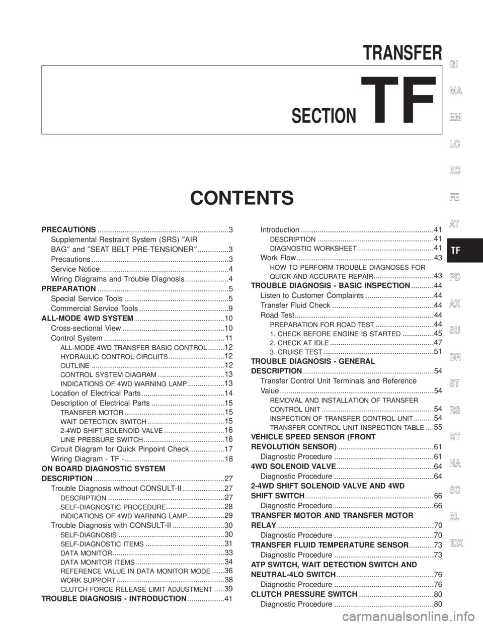
TRANSFER
SECTION
TF
CONTENTS
PRECAUTIONS...............................................................3
Supplemental Restraint System (SRS)²AIR
BAG²and²SEAT BELT PRE-TENSIONER²...............3
Precautions ..................................................................3
Service Notice..............................................................4
Wiring Diagrams and Trouble Diagnosis .....................4
PREPARATION...............................................................5
Special Service Tools ..................................................5
Commercial Service Tools ...........................................9
ALL-MODE 4WD SYSTEM...........................................10
Cross-sectional View .................................................10
Control System .......................................................... 11
ALL-MODE 4WD TRANSFER BASIC CONTROL........12
HYDRAULIC CONTROL CIRCUITS...........................12
OUTLINE................................................................12
CONTROL SYSTEM DIAGRAM................................13
INDICATIONS OF 4WD WARNING LAMP..................13
Location of Electrical Parts ........................................14
Description of Electrical Parts ...................................15
TRANSFER MOTOR................................................15
WAIT DETECTION SWITCH.....................................15
2-4WD SHIFT SOLENOID VALVE.............................16
LINE PRESSURE SWITCH.......................................16
Circuit Diagram for Quick Pinpoint Check.................17
Wiring Diagram - TF -................................................18
ON BOARD DIAGNOSTIC SYSTEM
DESCRIPTION...............................................................27
Trouble Diagnosis without CONSULT-II ....................27
DESCRIPTION........................................................27
SELF-DIAGNOSTIC PROCEDURE............................28
INDICATIONS OF 4WD WARNING LAMP..................29
Trouble Diagnosis with CONSULT-II .........................30
SELF-DIAGNOSIS...................................................30
SELF-DIAGNOSTIC ITEMS......................................31
DATA MONITOR......................................................33
DATA MONITOR ITEMS...........................................34
REFERENCE VALUE IN DATA MONITOR MODE......36
WORK SUPPORT....................................................38
CLUTCH FORCE RELEASE LIMIT ADJUSTMENT.....39
TROUBLE DIAGNOSIS - INTRODUCTION..................41Introduction ................................................................41
DESCRIPTION........................................................41
DIAGNOSTIC WORKSHEET.....................................41
Work Flow ..................................................................43
HOW TO PERFORM TROUBLE DIAGNOSES FOR
QUICK AND ACCURATE REPAIR
.............................43
TROUBLE DIAGNOSIS - BASIC INSPECTION...........44
Listen to Customer Complaints .................................44
Transfer Fluid Check .................................................44
Road Test...................................................................44
PREPARATION FOR ROAD TEST............................44
1. CHECK BEFORE ENGINE IS STARTED...............45
2. CHECK AT IDLE..................................................47
3. CRUISE TEST.....................................................51
TROUBLE DIAGNOSIS - GENERAL
DESCRIPTION...............................................................54
Transfer Control Unit Terminals and Reference
Value ..........................................................................54
REMOVAL AND INSTALLATION OF TRANSFER
CONTROL UNIT
......................................................54
INSPECTION OF TRANSFER CONTROL UNIT..........54
TRANSFER CONTROL UNIT INSPECTION TABLE....55
VEHICLE SPEED SENSOR (FRONT
REVOLUTION SENSOR)..............................................61
Diagnostic Procedure ................................................61
4WD SOLENOID VALVE...............................................64
Diagnostic Procedure ................................................64
2-4WD SHIFT SOLENOID VALVE AND 4WD
SHIFT SWITCH..............................................................66
Diagnostic Procedure ................................................66
TRANSFER MOTOR AND TRANSFER MOTOR
RELAY...........................................................................70
Diagnostic Procedure ................................................70
TRANSFER FLUID TEMPERATURE SENSOR............73
Diagnostic Procedure ................................................73
ATP SWITCH, WAIT DETECTION SWITCH AND
NEUTRAL-4LO SWITCH...............................................76
Diagnostic Procedure ................................................76
CLUTCH PRESSURE SWITCH....................................80
Diagnostic Procedure ................................................80
GI
MA
EM
LC
EC
FE
AT
PD
AX
SU
BR
ST
RS
BT
HA
SC
EL
IDX
Page 2238 of 2395

Supplemental Restraint System (SRS) ªAIR
BAGº and ªSEAT BELT PRE-TENSIONERº
NBTF0001The Supplemental Restraint System such as ªAIR BAGº and ªSEAT BELT PRE-TENSIONERº used along with
a seat belt, helps to reduce the risk or severity of injury to the driver and front passenger for certain types of
collision. The SRS system composition which is available to INFINITI QX4 is as follows:
IFor a frontal collision
The Supplemental Restraint System consists of driver air bag module (located in the center of the steer-
ing wheel), front passenger air bag module (located on the instrument panel on passenger side), seat belt
pre-tensioners, a diagnosis sensor unit, warning lamp, wiring harness and spiral cable.
IFor a side collision
The Supplemental Restraint System consists of side air bag module (located in the outer side of front seat),
satellite sensor, diagnosis sensor unit (one of components of air bags for a frontal collision), wiring harness,
warning lamp (one of components of air bags for a frontal collision).
Information necessary to service the system safely is included in theRSsection of this Service Manual.
WARNING:
ITo avoid rendering the SRS inoperative, which could increase the risk of personal injury or death
in the event of a collision which would result in air bag inflation, all maintenance must be performed
by an authorized INFINITI dealer.
IImproper maintenance, including incorrect removal and installation of the SRS, can lead to per-
sonal injury caused by unintentional activation of the system. For removal of Spiral Cable and Air
Bag Module, see the RS section.
IDo not use electrical test equipment on any circuit related to the SRS unless instructed to in this
Service Manual. Spiral cable and wiring harnesses covered with yellow insulation tape either just
before the harness connectors or for the complete harness are related to the SRS.
SEF289H
PrecautionsNBTF0092IBefore connecting or disconnecting the Transfer control
unit harness connector, turn ignition switch OFF and dis-
connect negative battery terminal. Failure to do so may
damage the Transfer control unit. Because battery voltage
is applied to Transfer control unit even if ignition switch
is turned off.
SEF291H
IWhen connecting or disconnecting pin connectors into or
from Transfer control unit, take care not to damage pin
terminals (bend or break).
Make sure that there are not any bends or breaks on
Transfer control unit pin terminal, when connecting pin
connectors.
GI
MA
EM
LC
EC
FE
AT
PD
AX
SU
BR
ST
RS
BT
HA
SC
EL
IDX
PRECAUTIONS
Supplemental Restraint System (SRS) ªAIR BAGº and ªSEAT BELT PRE-TENSIONERº
TF-3