elec INFINITI QX4 2001 Factory Service Manual
[x] Cancel search | Manufacturer: INFINITI, Model Year: 2001, Model line: QX4, Model: INFINITI QX4 2001Pages: 2395, PDF Size: 43.2 MB
Page 1997 of 2395
Supplemental Restraint System (SRS) ªAIR
BAGº and ªSEAT BELT PRE-TENSIONERº
NBMA0001The Supplemental Restraint System such as ªAIR BAGº and ªSEAT BELT PRE-TENSIONERº used along with
a seat belt, helps to reduce the risk or severity of injury to the driver and front passenger for certain types of
collision. The SRS system composition which is available to INFINITI QX4 is as follows:
IFor a frontal collision
The Supplemental Restraint System consists of driver air bag module (located in the center of the steer-
ing wheel), front passenger air bag module (located on the instrument panel on passenger side), seat belt
pre-tensioners, a diagnosis sensor unit, warning lamp, wiring harness and spiral cable.
IFor a side collision
The Supplemental Restraint System consists of side air bag module (located in the outer side of front seat),
satellite sensor, diagnosis sensor unit (one of components of air bags for a frontal collision), wiring harness,
warning lamp (one of components of air bags for a frontal collision).
Information necessary to service the system safely is included in theRS sectionof this Service Manual.
WARNING:
ITo avoid rendering the SRS inoperative, which could increase the risk of personal injury or death
in the event of a collision which would result in air bag inflation, all maintenance must be performed
by an authorized INFINITI dealer.
IImproper maintenance, including incorrect removal and installation of the SRS, can lead to per-
sonal injury caused by unintentional activation of the system. For removal of Spiral Cable and Air
Bag Module, see the RS section.
IDo not use electrical test equipment on any circuit related to the SRS unless instructed to in this
Service Manual. Spiral cable and wiring harnesses covered with yellow insulation tape either just
before the harness connectors or for the complete harness are related to the SRS.
PRECAUTIONS
Supplemental Restraint System (SRS) ªAIR BAGº and ªSEAT BELT PRE-TENSIONERº
MA-2
Page 2000 of 2395
ItemReference page
Brake pedal and
boosterCheck the pedal for smooth operation and make sure it has the proper dis-
tance under it when depressed fully. Check the brake booster function. Be
sure to keep floor mats away from the pedal.BR-14, ªBrake Pedal and
Bracketº and BR-19,
ªBrake Boosterº
Parking brakeCheck that the lever has the proper travel and make sure that the vehicle is
held securely on a fairly steep hill when only the parking brake is applied.BR-31, ªParking Brake
Controlº
Automatic transmis-
sion ªParkº mecha-
nismCheck that the lock release button on the selector lever operates properly
and smoothly. On a fairly steep hill check that the vehicle is held securely
with the selector lever in the ªPº position without applying any brakes.Ð
UNDER THE HOOD AND VEHICLE
The maintenance items listed here should be checked periodically (e.g. each time you check the engine oil or refuel).
ItemReference page
Windshield washer
fluidCheck that there is adequate fluid in the tank. Ð
Engine coolant levelCheck the coolant level when the engine is cold. MA-15
Radiator and hosesCheck the front of the radiator and clean off any dirt, insects, leaves, etc.,
that may have accumulated. Make sure the hoses have no cracks,
deformation, deterioration or loose connections.Ð
Brake fluid levelsMake sure that the brake fluid levels are between the ªMAXº and ªMINº lines
on the reservoir.MA-25
BatteryCheck the fluid level in each cell. It should be between the ªMAXº and ªMINº
lines.Ð
Engine drive beltsMake sure that no belt is frayed, worn, cracked or oily. MA-13
Engine oil levelCheck the level on the dipstick after parking the vehicle on a level spot and
turning off the engine.MA-18
Power steering fluid
level and linesCheck the level on the dipstick with the engine off. Check the lines for
improper attachment, leaks, cracks, etc.MA-27
Automatic transmis-
sion fluid levelCheck the level on the dipstick after putting the selector lever in ªPº with the
engine idling.MA-21
Exhaust systemMake sure there are no loose supports, cracks or holes. If the sound of the
exhaust seems unusual or there is a smell of exhaust fumes, immediately
locate the trouble and correct it.MA-21
UnderbodyThe underbody is frequently exposed to corrosive substances such as those
used on icy roads or to control dust. It is very important to remove these
substances, otherwise rust will form on the floor pan, frame, fuel lines and
around the exhaust system. At the end of winter, the underbody should be
thoroughly flushed with plain water, being careful to clean those areas where
mud and dirt can easily accumulate.Ð
Fluid leaksCheck under the vehicle for fuel, oil, water or other fluid leaks after the
vehicle has been parked for a while. Water dripping from the air conditioner
after use is normal. If you should notice any leaks or gasoline fumes are
evident, check for the cause and correct it immediately.Ð
GI
EM
LC
EC
FE
AT
TF
PD
AX
SU
BR
ST
RS
BT
HA
SC
EL
IDX
GENERAL MAINTENANCE
MA-5
Page 2016 of 2395
SMA211A
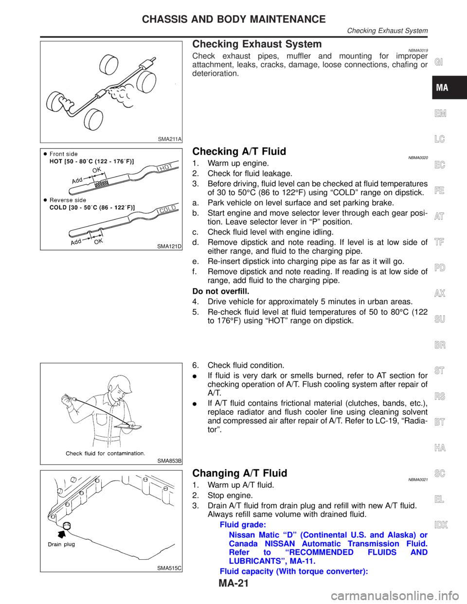
Checking Exhaust SystemNBMA0019Check exhaust pipes, muffler and mounting for improper
attachment, leaks, cracks, damage, loose connections, chafing or
deterioration.
SMA121D
Checking A/T FluidNBMA00201. Warm up engine.
2. Check for fluid leakage.
3. Before driving, fluid level can be checked at fluid temperatures
of 30 to 50ÉC (86 to 122ÉF) using ªCOLDº range on dipstick.
a. Park vehicle on level surface and set parking brake.
b. Start engine and move selector lever through each gear posi-
tion. Leave selector lever in ªPº position.
c. Check fluid level with engine idling.
d. Remove dipstick and note reading. If level is at low side of
either range, and fluid to the charging pipe.
e. Re-insert dipstick into charging pipe as far as it will go.
f. Remove dipstick and note reading. If reading is at low side of
range, add fluid to the charging pipe.
Do not overfill.
4. Drive vehicle for approximately 5 minutes in urban areas.
5. Re-check fluid level at fluid temperatures of 50 to 80ÉC (122
to 176ÉF) using ªHOTº range on dipstick.
SMA853B
6. Check fluid condition.
IIf fluid is very dark or smells burned, refer to AT section for
checking operation of A/T. Flush cooling system after repair of
A/T.
IIf A/T fluid contains frictional material (clutches, bands, etc.),
replace radiator and flush cooler line using cleaning solvent
and compressed air after repair of A/T. Refer to LC-19, ªRadia-
torº.
SMA515C
Changing A/T FluidNBMA00211. Warm up A/T fluid.
2. Stop engine.
3. Drain A/T fluid from drain plug and refill with new A/T fluid.
Always refill same volume with drained fluid.
Fluid grade:
Nissan Matic ªDº (Continental U.S. and Alaska) or
Canada NISSAN Automatic Transmission Fluid.
Refer to ªRECOMMENDED FLUIDS AND
LUBRICANTSº, MA-11.
Fluid capacity (With torque converter):
GI
EM
LC
EC
FE
AT
TF
PD
AX
SU
BR
ST
RS
BT
HA
SC
EL
IDX
CHASSIS AND BODY MAINTENANCE
Checking Exhaust System
MA-21
Page 2034 of 2395
SPD131
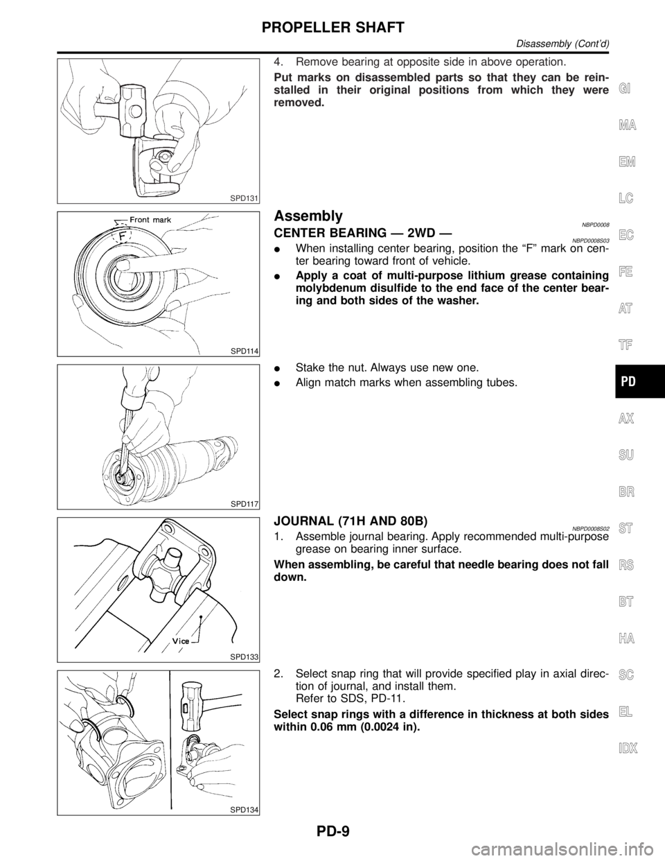
4. Remove bearing at opposite side in above operation.
Put marks on disassembled parts so that they can be rein-
stalled in their original positions from which they were
removed.
SPD114
AssemblyNBPD0008CENTER BEARING Ð 2WD ÐNBPD0008S03IWhen installing center bearing, position the ªFº mark on cen-
ter bearing toward front of vehicle.
IApply a coat of multi-purpose lithium grease containing
molybdenum disulfide to the end face of the center bear-
ing and both sides of the washer.
SPD117
IStake the nut. Always use new one.
IAlign match marks when assembling tubes.
SPD133
JOURNAL (71H AND 80B)NBPD0008S021. Assemble journal bearing. Apply recommended multi-purpose
grease on bearing inner surface.
When assembling, be careful that needle bearing does not fall
down.
SPD134
2. Select snap ring that will provide specified play in axial direc-
tion of journal, and install them.
Refer to SDS, PD-11.
Select snap rings with a difference in thickness at both sides
within 0.06 mm (0.0024 in).
GI
MA
EM
LC
EC
FE
AT
TF
AX
SU
BR
ST
RS
BT
HA
SC
EL
IDX
PROPELLER SHAFT
Disassembly (Cont'd)
PD-9
Page 2039 of 2395
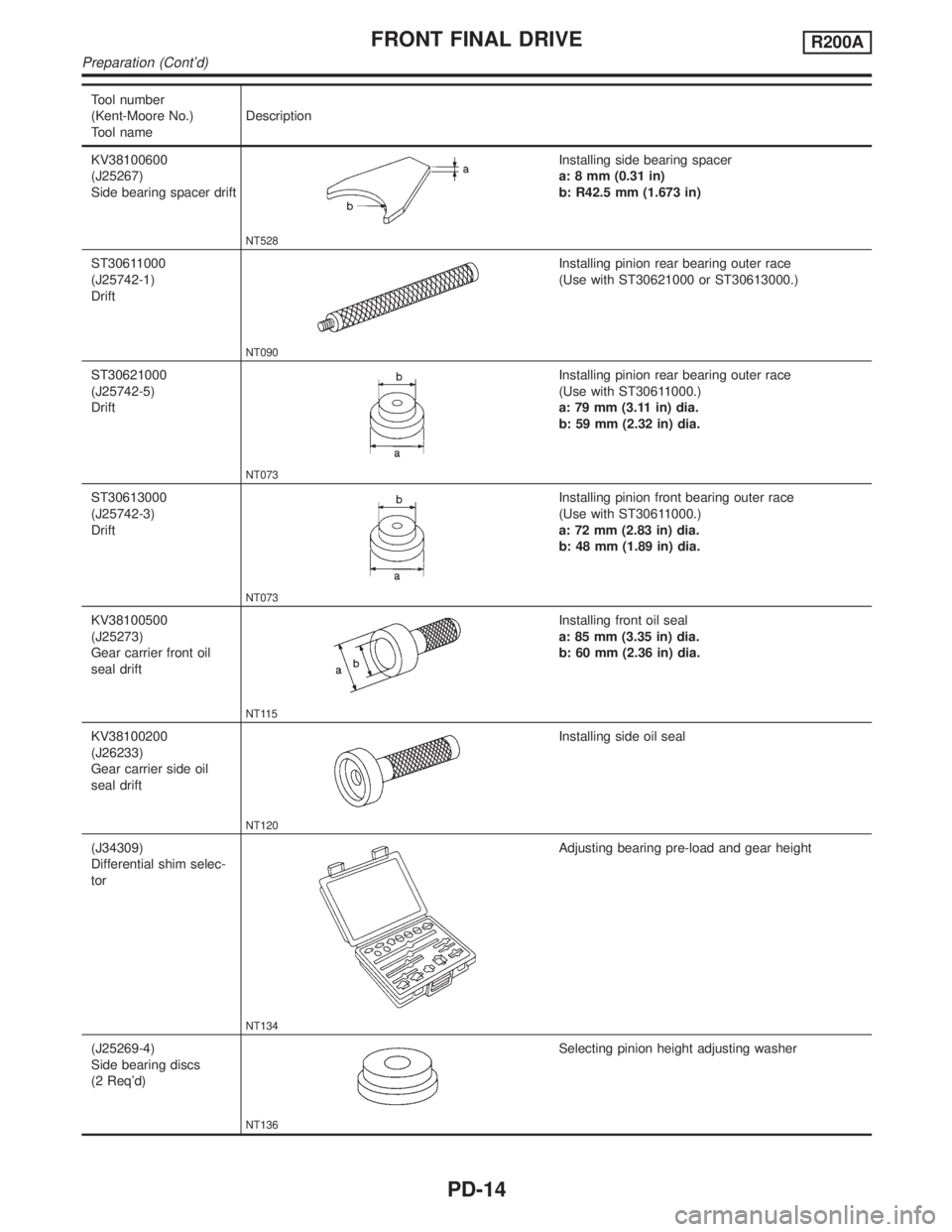
Tool number
(Kent-Moore No.)
Tool nameDescription
KV38100600
(J25267)
Side bearing spacer drift
NT528
Installing side bearing spacer
a: 8 mm (0.31 in)
b: R42.5 mm (1.673 in)
ST30611000
(J25742-1)
Drift
NT090
Installing pinion rear bearing outer race
(Use with ST30621000 or ST30613000.)
ST30621000
(J25742-5)
Drift
NT073
Installing pinion rear bearing outer race
(Use with ST30611000.)
a: 79 mm (3.11 in) dia.
b: 59 mm (2.32 in) dia.
ST30613000
(J25742-3)
Drift
NT073
Installing pinion front bearing outer race
(Use with ST30611000.)
a: 72 mm (2.83 in) dia.
b: 48 mm (1.89 in) dia.
KV38100500
(J25273)
Gear carrier front oil
seal drift
NT115
Installing front oil seal
a: 85 mm (3.35 in) dia.
b: 60 mm (2.36 in) dia.
KV38100200
(J26233)
Gear carrier side oil
seal drift
NT120
Installing side oil seal
(J34309)
Differential shim selec-
tor
NT134
Adjusting bearing pre-load and gear height
(J25269-4)
Side bearing discs
(2 Req'd)
NT136
Selecting pinion height adjusting washer
FRONT FINAL DRIVER200A
Preparation (Cont'd)
PD-14
Page 2049 of 2395
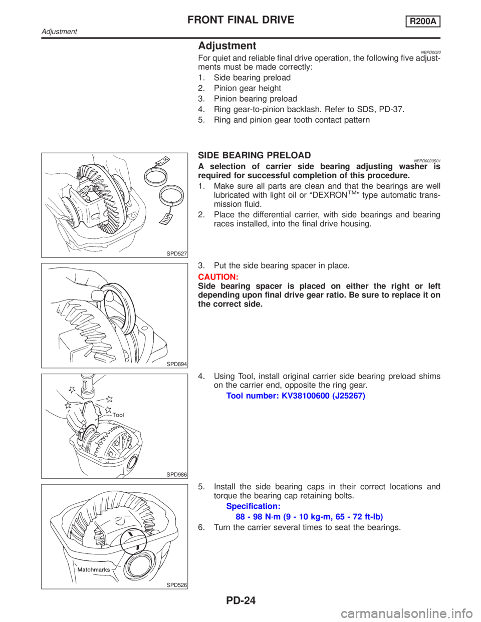
AdjustmentNBPD0020For quiet and reliable final drive operation, the following five adjust-
ments must be made correctly:
1. Side bearing preload
2. Pinion gear height
3. Pinion bearing preload
4. Ring gear-to-pinion backlash. Refer to SDS, PD-37.
5. Ring and pinion gear tooth contact pattern
SPD527
SIDE BEARING PRELOADNBPD0020S01A selection of carrier side bearing adjusting washer is
required for successful completion of this procedure.
1. Make sure all parts are clean and that the bearings are well
lubricated with light oil or ªDEXRON
TMº type automatic trans-
mission fluid.
2. Place the differential carrier, with side bearings and bearing
races installed, into the final drive housing.
SPD894
3. Put the side bearing spacer in place.
CAUTION:
Side bearing spacer is placed on either the right or left
depending upon final drive gear ratio. Be sure to replace it on
the correct side.
SPD986
4. Using Tool, install original carrier side bearing preload shims
on the carrier end, opposite the ring gear.
Tool number: KV38100600 (J25267)
SPD526
5. Install the side bearing caps in their correct locations and
torque the bearing cap retaining bolts.
Specification:
88 - 98 N´m (9 - 10 kg-m, 65 - 72 ft-lb)
6. Turn the carrier several times to seat the bearings.
FRONT FINAL DRIVER200A
Adjustment
PD-24
Page 2050 of 2395
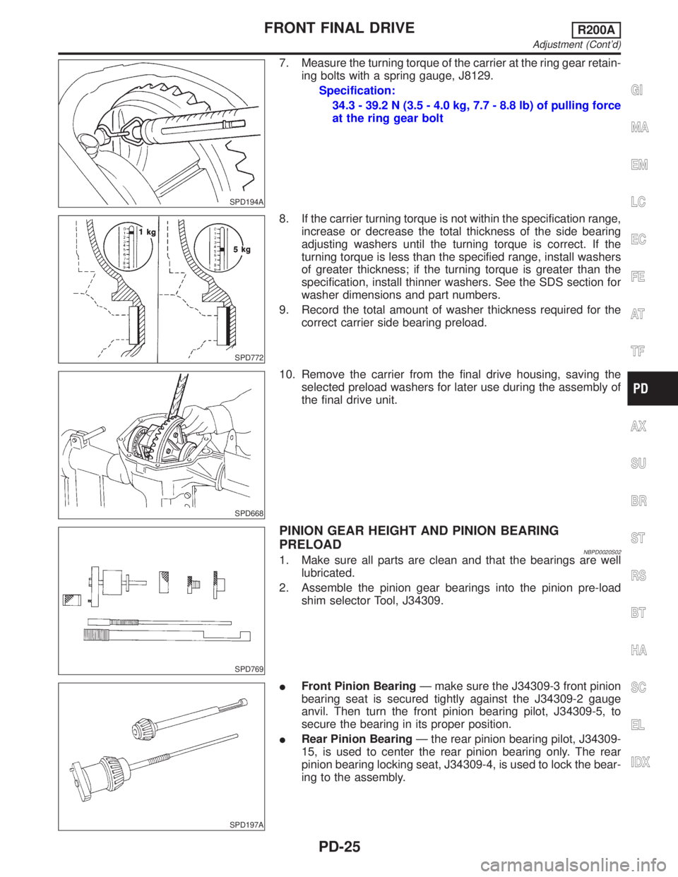
SPD194A
7. Measure the turning torque of the carrier at the ring gear retain-
ing bolts with a spring gauge, J8129.
Specification:
34.3 - 39.2 N (3.5 - 4.0 kg, 7.7 - 8.8 lb) of pulling force
at the ring gear bolt
SPD772
8. If the carrier turning torque is not within the specification range,
increase or decrease the total thickness of the side bearing
adjusting washers until the turning torque is correct. If the
turning torque is less than the specified range, install washers
of greater thickness; if the turning torque is greater than the
specification, install thinner washers. See the SDS section for
washer dimensions and part numbers.
9. Record the total amount of washer thickness required for the
correct carrier side bearing preload.
SPD668
10. Remove the carrier from the final drive housing, saving the
selected preload washers for later use during the assembly of
the final drive unit.
SPD769
PINION GEAR HEIGHT AND PINION BEARING
PRELOAD
NBPD0020S021. Make sure all parts are clean and that the bearings are well
lubricated.
2. Assemble the pinion gear bearings into the pinion pre-load
shim selector Tool, J34309.
SPD197A
IFront Pinion BearingÐ make sure the J34309-3 front pinion
bearing seat is secured tightly against the J34309-2 gauge
anvil. Then turn the front pinion bearing pilot, J34309-5, to
secure the bearing in its proper position.
IRear Pinion BearingÐ the rear pinion bearing pilot, J34309-
15, is used to center the rear pinion bearing only. The rear
pinion bearing locking seat, J34309-4, is used to lock the bear-
ing to the assembly.
GI
MA
EM
LC
EC
FE
AT
TF
AX
SU
BR
ST
RS
BT
HA
SC
EL
IDX
FRONT FINAL DRIVER200A
Adjustment (Cont'd)
PD-25
Page 2051 of 2395
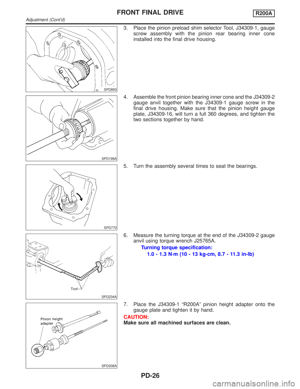
SPD893
3. Place the pinion preload shim selector Tool, J34309-1, gauge
screw assembly with the pinion rear bearing inner cone
installed into the final drive housing.
SPD199A
4. Assemble the front pinion bearing inner cone and the J34309-2
gauge anvil together with the J34309-1 gauge screw in the
final drive housing. Make sure that the pinion height gauge
plate, J34309-16, will turn a full 360 degrees, and tighten the
two sections together by hand.
SPD770
5. Turn the assembly several times to seat the bearings.
SPD234A
6. Measure the turning torque at the end of the J34309-2 gauge
anvil using torque wrench J25765A.
Turning torque specification:
1.0 - 1.3 N´m (10 - 13 kg-cm, 8.7 - 11.3 in-lb)
SPD208A
7. Place the J34309-1 ªR200Aº pinion height adapter onto the
gauge plate and tighten it by hand.
CAUTION:
Make sure all machined surfaces are clean.
FRONT FINAL DRIVER200A
Adjustment (Cont'd)
PD-26
Page 2052 of 2395
SPD209A
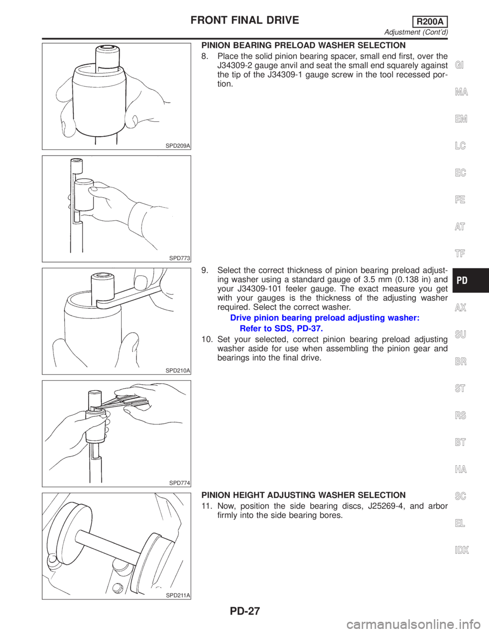
PINION BEARING PRELOAD WASHER SELECTION
8. Place the solid pinion bearing spacer, small end first, over the
J34309-2 gauge anvil and seat the small end squarely against
the tip of the J34309-1 gauge screw in the tool recessed por-
tion.
SPD773
SPD210A
SPD774
9. Select the correct thickness of pinion bearing preload adjust-
ing washer using a standard gauge of 3.5 mm (0.138 in) and
your J34309-101 feeler gauge. The exact measure you get
with your gauges is the thickness of the adjusting washer
required. Select the correct washer.
Drive pinion bearing preload adjusting washer:
Refer to SDS, PD-37.
10. Set your selected, correct pinion bearing preload adjusting
washer aside for use when assembling the pinion gear and
bearings into the final drive.
SPD211A
PINION HEIGHT ADJUSTING WASHER SELECTION
11. Now, position the side bearing discs, J25269-4, and arbor
firmly into the side bearing bores.
GI
MA
EM
LC
EC
FE
AT
TF
AX
SU
BR
ST
RS
BT
HA
SC
EL
IDX
FRONT FINAL DRIVER200A
Adjustment (Cont'd)
PD-27
Page 2053 of 2395
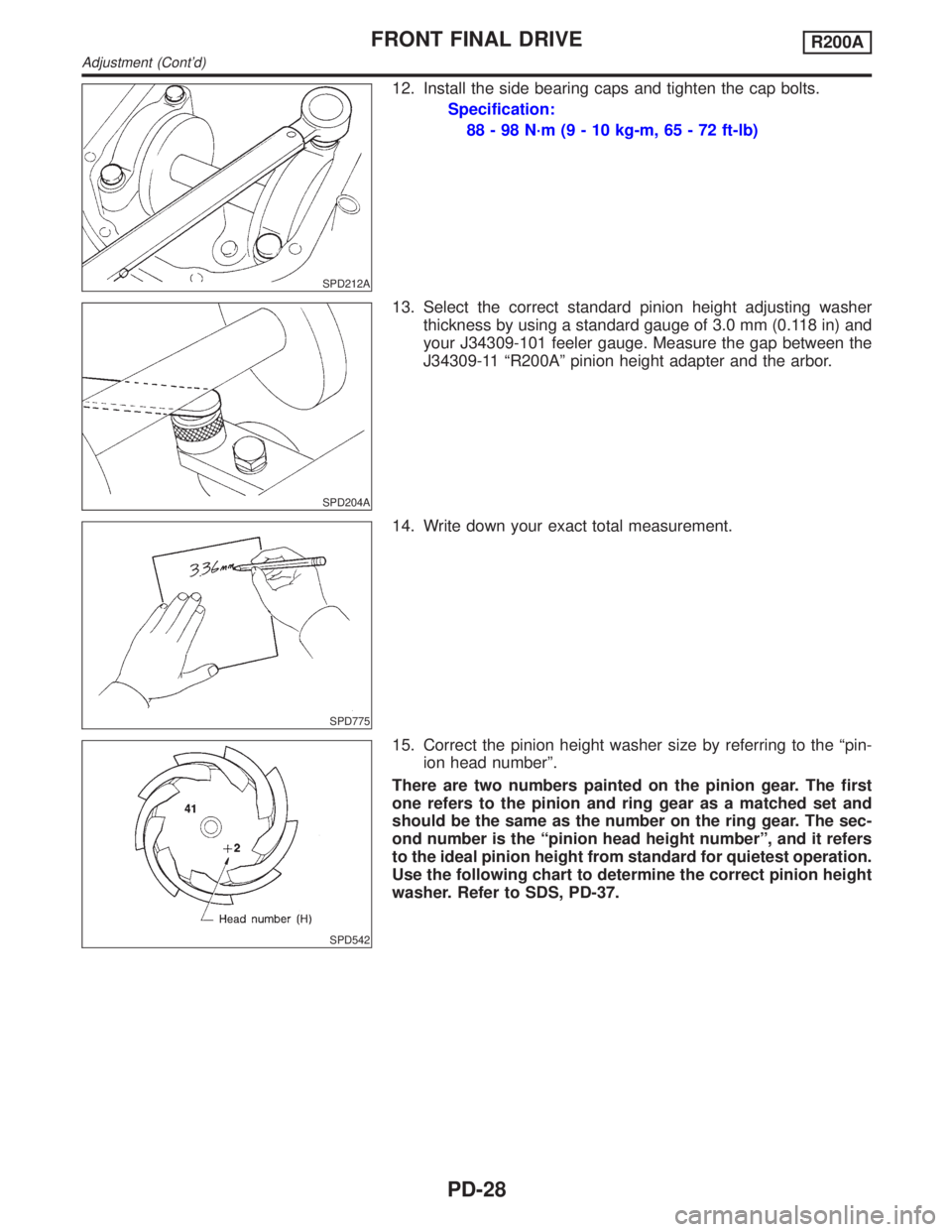
SPD212A
12. Install the side bearing caps and tighten the cap bolts.
Specification:
88 - 98 N´m (9 - 10 kg-m, 65 - 72 ft-lb)
SPD204A
13. Select the correct standard pinion height adjusting washer
thickness by using a standard gauge of 3.0 mm (0.118 in) and
your J34309-101 feeler gauge. Measure the gap between the
J34309-11 ªR200Aº pinion height adapter and the arbor.
SPD775
14. Write down your exact total measurement.
SPD542
15. Correct the pinion height washer size by referring to the ªpin-
ion head numberº.
There are two numbers painted on the pinion gear. The first
one refers to the pinion and ring gear as a matched set and
should be the same as the number on the ring gear. The sec-
ond number is the ªpinion head height numberº, and it refers
to the ideal pinion height from standard for quietest operation.
Use the following chart to determine the correct pinion height
washer. Refer to SDS, PD-37.
FRONT FINAL DRIVER200A
Adjustment (Cont'd)
PD-28