engine INFINITI QX4 2001 Factory Service Manual
[x] Cancel search | Manufacturer: INFINITI, Model Year: 2001, Model line: QX4, Model: INFINITI QX4 2001Pages: 2395, PDF Size: 43.2 MB
Page 2017 of 2395

2WD, 4WD model
8.5(9 US qt, 7-1/2 Imp qt)
Drain plug:
: 29 - 39 N´m (3.0 - 4.0 kg-m, 22 - 29 ft-lb)
4. Run engine at idle speed for five minutes.
5. Check fluid level and condition. Refer to MA-21, ªChecking A/T
Fluidº. If fluid is still dirty, repeat steps 2 through 5.
SMA439B
Checking All-mode 4WD Transfer FluidNBMA0022Check for oil leakage and fluid level.
A/T fluid is used for the all-mode 4WD transfer in the factory.
Never start engine while checking fluid level.
Filler plug:
: 10 - 20 N´m (1.0 - 2.0 kg-m, 87 - 174 in-lb)
SMA444B
Changing All-mode 4WD Transfer FluidNBMA0023When changing all-mode 4WD transfer fluid completely, A/T fluid
may be used.
Fluid grade:
Nissan Matic ªDº (Continental U.S. and Alaska) or
Canada NISSAN Automatic Transmission Fluid.
Refer to ªFluids and Lubricantsº, ªRECOMMENDED
FLUIDS AND LUBRICANTSº, MA-11.
Fluid capacity:
3.0(3-1/8 US qt, 2-5/8 Imp qt)
Drain plug:
: 10 - 20 N´m (1.0 - 2.0 kg-m, 87 - 174 in-lb)
CHASSIS AND BODY MAINTENANCE
Changing A/T Fluid (Cont'd)
MA-22
Page 2022 of 2395

SST280B
Checking Power Steering Fluid and LinesNBMA0035CHECKING FLUID LEVELNBMA0035S01ICheck fluid level with engine off.
ICheck fluid level with dipstick on reservoir cap. Use ªHOTº
range at fluid temperatures of 50 to 80ÉC (122 to 176ÉF). Use
ªCOLDº range at fluid temperatures of 0 to 30ÉC (32 to 86ÉF).
CAUTION:
IDo not overfill.
IRecommended fluid is Genuine NISSAN PSF II or equiva-
lent. Refer to ªRECOMMENDED FLUIDS AND
LUBRICANTSº, MA-11.
SST118B
CHECKING LINESNBMA0035S02ICheck lines for improper attachment, leaks, cracks, damage,
loose connections, chafing and deterioration.
ICheck rack boots for accumulation of power steering fluid.
Lubricating Locks, Hinges and Hood LatchesNBMA0036
SMA897C
GI
EM
LC
EC
FE
AT
TF
PD
AX
SU
BR
ST
RS
BT
HA
SC
EL
IDX
CHASSIS AND BODY MAINTENANCE
Checking Power Steering Fluid and Lines
MA-27
Page 2024 of 2395

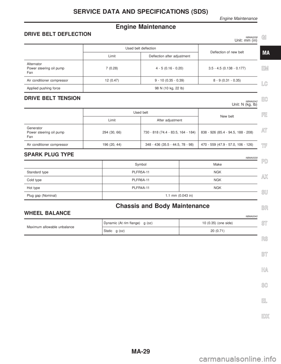
Engine Maintenance
DRIVE BELT DEFLECTIONNBMA0038Unit: mm (in)
Used belt deflection
Deflection of new belt
Limit Deflection after adjustment
Alternator
Power steering oil pump
Fan7 (0.28)4 - 5 (0.16 - 0.20) 3.5 - 4.5 (0.138 - 0.177)
Air conditioner compressor 12 (0.47) 9 - 10 (0.35 - 0.39)8 - 9 (0.31 - 0.35)
Applied pushing force 98 N (10 kg, 22 lb)
DRIVE BELT TENSIONNBMA0042Unit: N (kg, lb)
Used belt
New belt
Limit After adjustment
Generator
Power steering oil pump
Fan294 (30, 66) 730 - 818 (74.4 - 83.5, 164 - 184) 838 - 926 (85.4 - 94.5, 188 - 208)
Air conditioner compressor 196 (20, 44) 348 - 436 (35.5 - 44.5, 78 - 98) 470 - 559 (47.9 - 57.0, 106 - 126)
SPARK PLUG TYPENBMA0039
Symbol Make
Standard type PLFR5A-11 NGK
Cold type PLFR6A-11 NGK
Hot type PLFR4A-11 NGK
Plug gap (Nominal) 1.1 mm (0.043 in)
Chassis and Body Maintenance
WHEEL BALANCENBMA0040
Maximum allowable unbalanceDynamic (At rim flange) g (oz) 10 (0.35) (one side)
Static g (oz) 20 (0.71)
GI
EM
LC
EC
FE
AT
TF
PD
AX
SU
BR
ST
RS
BT
HA
SC
EL
IDX
SERVICE DATA AND SPECIFICATIONS (SDS)
Engine Maintenance
MA-29
Page 2073 of 2395

DISASSEMBLYNBPD0036
SPD404A
CAUTION:
Do not run engine when one wheel (rear) is off the ground.
SPD275
1. Remove side bearing inner cone with Tool.
2. Loosen ring gear bolts in a criss-cross pattern.
3. Tap ring gear off gear case with a soft hammer.
Tap evenly all around to keep ring gear from binding.
SPD363A
4. Remove couple bolts on differential cases A and B with a
press.
Tool number: ST33081000 ( Ð )
5. Separate differential case A and B.
Draw out component parts (discs and plates, etc.).
Put marks on gears and pressure rings so that they can be
reinstalled in their original positions from which they were
removed.
REAR FINAL DRIVEH233B
Limited Slip Differential (Cont'd)
PD-48
Page 2155 of 2395

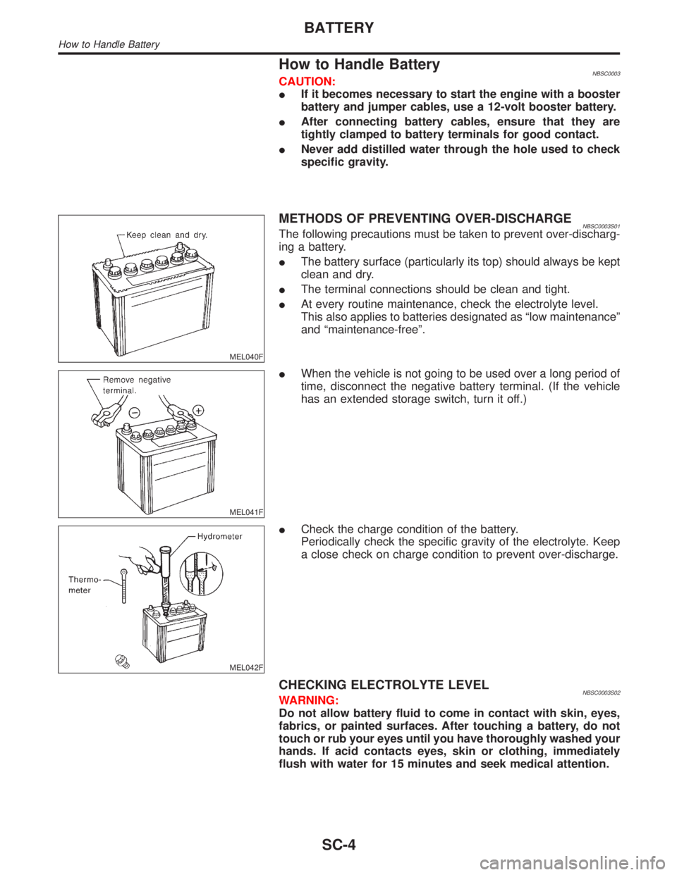
How to Handle BatteryNBSC0003CAUTION:
IIf it becomes necessary to start the engine with a booster
battery and jumper cables, use a 12-volt booster battery.
IAfter connecting battery cables, ensure that they are
tightly clamped to battery terminals for good contact.
INever add distilled water through the hole used to check
specific gravity.
MEL040F
METHODS OF PREVENTING OVER-DISCHARGENBSC0003S01The following precautions must be taken to prevent over-discharg-
ing a battery.
IThe battery surface (particularly its top) should always be kept
clean and dry.
IThe terminal connections should be clean and tight.
IAt every routine maintenance, check the electrolyte level.
This also applies to batteries designated as ªlow maintenanceº
and ªmaintenance-freeº.
MEL041F
IWhen the vehicle is not going to be used over a long period of
time, disconnect the negative battery terminal. (If the vehicle
has an extended storage switch, turn it off.)
MEL042F
ICheck the charge condition of the battery.
Periodically check the specific gravity of the electrolyte. Keep
a close check on charge condition to prevent over-discharge.
CHECKING ELECTROLYTE LEVELNBSC0003S02WARNING:
Do not allow battery fluid to come in contact with skin, eyes,
fabrics, or painted surfaces. After touching a battery, do not
touch or rub your eyes until you have thoroughly washed your
hands. If acid contacts eyes, skin or clothing, immediately
flush with water for 15 minutes and seek medical attention.
BATTERY
How to Handle Battery
SC-4
Page 2161 of 2395

System DescriptionNBSC0004Power is supplied at all times
Ito ignition switch terminal 1
Ithrough 40A fusible link (lettere, located in the fuse and fusible link box).
With the ignition switch in the ON or START position, power is supplied through 10A fuse [No. 18, located in
the fuse block (J/B)].
Ito park/neutral position relay terminal 1.
Also, with the ignition switch in the START position, power is supplied
Ifrom ignition switch terminal 5
Ito park/neutral position relay terminal 6.
With the selector lever in the P or N position, ground is supplied
Ito park/neutral position relay terminal 2 through the park/neutral position switch.
Then park/neutral position relay is energized and power is supplied
Ifrom park/neutral position relay terminal 7
Ito terminal 2 of the starter motor windings.
The starter motor plunger closes and provides a closed circuit between the battery and starter motor. The
starter motor is grounded to the engine block. With power and ground supplied, cranking occurs and the engine
starts.
STARTING SYSTEM
System Description
SC-10
Page 2163 of 2395

Trouble Diagnoses with
Battery/Starting/Charging System Tester
NBSC0019NOTE:
To ensure a complete and thorough diagnosis, the battery, starter
and alternator test segments must be done as a set from start to
finish.
SEL408X
1. Turn off all loads on the vehicle electrical system.
2. Perform battery test with Battery/Starting/Charging system
tester. Refer to SC-7.
3. Press ªENTERº to begin the starting system test.
SEL409X
4. Start the engine.
SEL410X
5. Diagnosis result is displayed on the tester. Refer to ªDIAG-
NOSTIC RESULT ITEM CHARTº, SC-13.
NOTE:
IIf the starter performs normally but the engine does not start,
perform engine diagnosis.
IFor intermittent ªNO CRANKº or ªNO STARTER OPERATIONº
incidents, go to DIAGNOSTIC PROCEDURE 2.
STARTING SYSTEM
Trouble Diagnoses with Battery/Starting/Charging System Tester
SC-12
Page 2166 of 2395

DIAGNOSTIC PROCEDURE 1NBSC0019S03Check ªBº Terminal CircuitNBSC0019S0301
1 CHECK POWER SUPPLY FOR STARTER MOTOR ªBº TERMINAL
1. Remove the fuel pump fuse.
2. Crank or start the engine (where possible) until the fuel pressure is released.
3. Turn the ignition OFF.
4. Check that the starter motor terminal 1 connection is clean and tight.
5. Check voltage between starter motor terminal 1 and ground using a digital circuit tester.
SEL412X
OK or NG
OK©GO TO 2.
NG©Check harness between the battery and the starter motor for open circuit.
2 CHECK BATTERY CABLE CONNECTION QUALITY (VOLTAGE DROP TEST)
1. Check voltage between starter motor terminal 1 and battery positive terminal using a digital circuit tester.
SEL413X
OK or NG
OK©GO TO 3.
NG©Check harness between the battery and the starter motor for poor continuity.
GI
MA
EM
LC
EC
FE
AT
TF
PD
AX
SU
BR
ST
RS
BT
HA
EL
IDX
STARTING SYSTEM
Trouble Diagnoses with Battery/Starting/Charging System Tester (Cont'd)
SC-15
Page 2168 of 2395

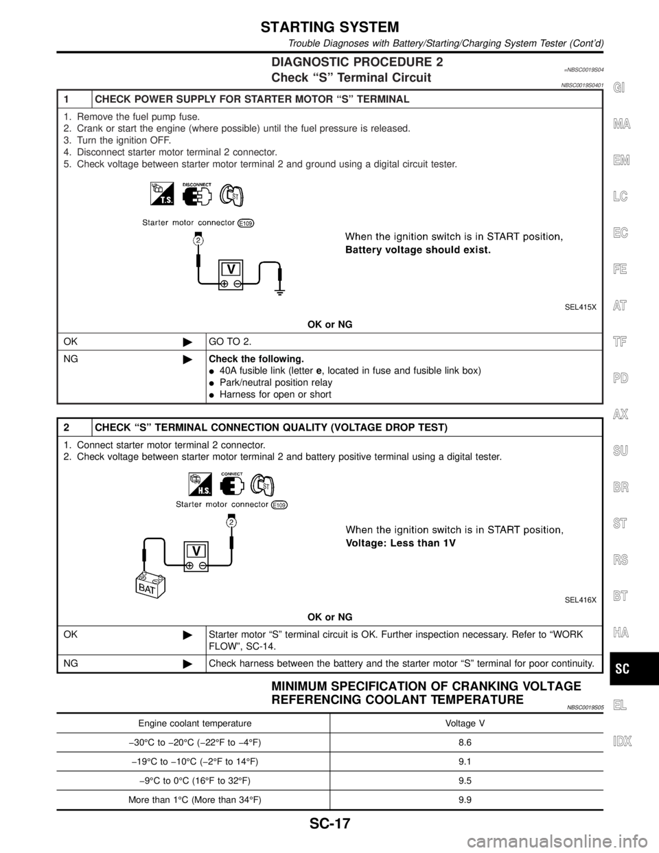
DIAGNOSTIC PROCEDURE 2=NBSC0019S04Check ªSº Terminal CircuitNBSC0019S0401
1 CHECK POWER SUPPLY FOR STARTER MOTOR ªSº TERMINAL
1. Remove the fuel pump fuse.
2. Crank or start the engine (where possible) until the fuel pressure is released.
3. Turn the ignition OFF.
4. Disconnect starter motor terminal 2 connector.
5. Check voltage between starter motor terminal 2 and ground using a digital circuit tester.
SEL415X
OK or NG
OK©GO TO 2.
NG©Check the following.
I40A fusible link (lettere, located in fuse and fusible link box)
IPark/neutral position relay
IHarness for open or short
2 CHECK ªSº TERMINAL CONNECTION QUALITY (VOLTAGE DROP TEST)
1. Connect starter motor terminal 2 connector.
2. Check voltage between starter motor terminal 2 and battery positive terminal using a digital tester.
SEL416X
OK or NG
OK©Starter motor ªSº terminal circuit is OK. Further inspection necessary. Refer to ªWORK
FLOWº, SC-14.
NG©Check harness between the battery and the starter motor ªSº terminal for poor continuity.
MINIMUM SPECIFICATION OF CRANKING VOLTAGE
REFERENCING COOLANT TEMPERATURE
NBSC0019S05
Engine coolant temperature Voltage V
þ30ÉC to þ20ÉC (þ22ÉF to þ4ÉF) 8.6
þ19ÉC to þ10ÉC (þ2ÉF to 14ÉF) 9.1
þ9ÉC to 0ÉC (16ÉF to 32ÉF) 9.5
More than 1ÉC (More than 34ÉF) 9.9
GI
MA
EM
LC
EC
FE
AT
TF
PD
AX
SU
BR
ST
RS
BT
HA
EL
IDX
STARTING SYSTEM
Trouble Diagnoses with Battery/Starting/Charging System Tester (Cont'd)
SC-17
Page 2170 of 2395

System DescriptionNBSC0009The alternator provides DC voltage to operate the vehicle's electrical system and to keep the battery charged.
The voltage output is controlled by the IC regulator.
Power is supplied at all times to alternator terminal S through:
I120A fusible link (lettera, located in the fuse and fusible link box), and
I7.5A fuse (No. 65, located in the fuse and fusible link box).
Terminal B supplies power to charge the battery and operate the vehicle's electrical system. Output voltage
is controlled by the IC regulator at terminal S detecting the input voltage. The charging circuit is protected by
the 120A fusible link.
Terminal E of the alternator supplies ground through body ground E101.
With the ignition switch in the ON or START position, power is supplied
Ithrough 10A fuse [No. 8, located in the fuse block (J/B)]
Ito combination meter terminal 12 for the charge warning lamp.
Ground is supplied to terminal 43 of the combination meter through terminal L of the alternator. With power
and ground supplied, the charge warning lamp will illuminate. When the alternator is providing sufficient volt-
age with the engine running, the ground is opened and the charge warning lamp will go off.
If the charge warning lamp illuminates with the engine running, a fault is indicated.GI
MA
EM
LC
EC
FE
AT
TF
PD
AX
SU
BR
ST
RS
BT
HA
EL
IDX
CHARGING SYSTEM
System Description
SC-19