check engine INFINITI QX56 2007 Factory Owners Manual
[x] Cancel search | Manufacturer: INFINITI, Model Year: 2007, Model line: QX56, Model: INFINITI QX56 2007Pages: 3061, PDF Size: 64.56 MB
Page 263 of 3061

TROUBLE DIAGNOSIS FOR SYMPTOMS
AT-193
< SERVICE INFORMATION >
D
E
F
G
H
I
J
K
L
MA
B
AT
N
O
P
1. Turn ignition switch “ON”.
2. Select "ECU INPUT SIGNALS" in "DATA MONITOR" mode for
"A/T" with CONSULT-II.
3. Read out "OD CONT SW" switch moving selector lever to each
position.
Without CONSULT-II
1. Turn ignition switch “ON”. (Do not start engine)
2. Check voltage between A/T device harness connector terminal
and ground.
OK or NG
OK >> GO TO 3.
NG >> Repair or replace damaged parts.
3.CHECK A/T FLUID LEVEL
Check the A/T fluid level. Refer to AT-13, "
Checking Automatic
Transmission Fluid (ATF)".
OK or NG
OK >> GO TO 4.
NG >> Refill ATF.
4.CHECK CONTROL CABLE
Check the control cable.
• Refer to AT-208, "
Checking of A/T Position".
OK or NG
OK >> GO TO 5.
NG >> Adjust control cable. Refer to AT-208, "
Adjustment of A/
T Position".
Monitor item Condition Display value
OD CONT SWWhen setting the selector
lever to "4" and "3" posi-
tion.ON
When setting selector le-
ver to other positions.OFF
LCIA0339E
Item Connector No. Terminal No. ConditionData
(Approx.)
4th position
switchM203 1 - GroundWhen setting
the selector le-
ver to "4" and
"3" position.0V
When setting
selector lever
to other posi-
tions.Battery volt-
age
LCIA0340E
SAT638A
LCIA0345E
Page 268 of 3061

AT-198
< SERVICE INFORMATION >
TROUBLE DIAGNOSIS FOR SYMPTOMS
1. Turn ignition switch “ON”.
2. Select "ECU INPUT SIGNALS" in "DATA MONITOR" mode for
"A/T" with CONSULT-II.
3. Read out "1 POSITION SW" switch moving selector lever to
each position.
Without CONSULT-II
1. Turn ignition switch “ON”. (Do not start engine)
2. Check voltage between A/T device harness connector terminal
and ground.
OK or NG
OK >> GO TO 3.
NG >> Repair or replace damaged parts.
3.CHECK A/T FLUID LEVEL
Check the A/T fluid level. Refer to AT-13, "
Checking Automatic
Transmission Fluid (ATF)".
OK or NG
OK >> GO TO 4.
NG >> Refill ATF.
4.CHECK CONTROL CABLE
Check the control cable.
• Refer to AT-208, "
Checking of A/T Position".
OK or NG
OK >> GO TO 5.
NG >> Adjust control cable. Refer to AT-208, "
Adjustment of A/
T Position".
5.CHECK A/T FLUID CONDITION
Monitor item Condition Display value
1 POSITION SWWhen setting the selector
lever to "1" position.ON
When setting selector le-
ver to other positions.OFF
LCIA0339E
Item Connector No. Terminal No. ConditionData
(Approx.)
1st position
switchM203 7 - GroundWhen setting
the selector le-
ver to "1" posi-
tion.0V
When setting
selector lever
to other posi-
tions.Battery volt-
age
LCIA0341E
SAT638A
LCIA0345E
Page 269 of 3061

TROUBLE DIAGNOSIS FOR SYMPTOMS
AT-199
< SERVICE INFORMATION >
D
E
F
G
H
I
J
K
L
MA
B
AT
N
O
P
1. Remove oil pan. Refer to AT-210, "Control Valve with TCM and A/T Fluid Temperature Sensor 2".
2. Check A/T fluid condition. Refer to AT-51, "
Inspections Before
Trouble Diagnosis".
OK or NG
OK >> GO TO 6.
NG >> GO TO 9.
6.DETECT MALFUNCTIONING ITEM
• Check the malfunction items. If any items are damaged, repair or replace damaged parts. Refer to AT-60,
"Symptom Chart" (Symptom No.17).
OK or NG
OK >> GO TO 7.
NG >> Repair or replace damaged parts.
7.CHECK SYMPTOM
Check again. Refer to AT-58, "
Cruise Test - Part 2".
OK or NG
OK >>INSPECTION END
NG >> GO TO 8.
8.PERFORM TCM INSPECTION
1. Perform TCM input/output signals inspection. Refer to AT-82, "
TCM Input/Output Signal Reference
Va l u e".
2. If NG, recheck A/T assembly harness connector terminals for damage or loose connection with harness
connector.
OK or NG
OK >>INSPECTION END
NG >> Repair or replace damaged parts.
9.DETECT MALFUNCTIONING ITEM
• Check the malfunction items. If any items are damaged, repair or replace damaged parts. Refer to AT-60,
"Symptom Chart" (Symptom No.17).
OK or NG
OK >> GO TO 7.
NG >> Repair or replace damaged parts.
Vehicle Does Not Decelerate By Engine BrakeINFOID:0000000003532468
SYMPTOM:
No engine brake is applied when the gear is shifted from the 22 to 11.
DIAGNOSTIC PROCEDURE
1.CHECK SELF-DIAGNOSIS RESULTS
Perform self-diagnosis.
Do the self-diagnosis results indicate PNP switch, ATF pressure switch 5?
YES >> Check the malfunctioning system. Refer to AT- 9 9' AT-154.
NO >> GO TO 2.
2.CHECK 1ST POSITION SWITCH CIRCUIT
With CONSULT-II
SCIA5199E
Page 270 of 3061

AT-200
< SERVICE INFORMATION >
TROUBLE DIAGNOSIS FOR SYMPTOMS
1. Turn ignition switch “ON”.
2. Select "ECU INPUT SIGNALS" in "DATA MONITOR" mode for
"A/T" with CONSULT-II.
3. Read out "1 POSITION SW" moving switch selector lever to
each position.
Without CONSULT-II
1. Turn ignition switch “ON”. (Do not start engine)
2. Check voltage between A/T device harness connector terminal
and ground.
OK or NG
OK >> GO TO 3.
NG >> Repair or replace damaged parts.
3.CHECK A/T FLUID LEVEL
Check the A/T fluid level. Refer to AT-13, "
Checking Automatic
Transmission Fluid (ATF)".
OK or NG
OK >> GO TO 4.
NG >> Refill ATF.
4.CHECK CONTROL CABLE
Check the control cable.
• Refer to AT-208, "
Checking of A/T Position".
OK or NG
OK >> GO TO 5.
NG >> Adjust control cable. Refer to AT-208, "
Adjustment of A/
T Position".
5.CHECK A/T FLUID CONDITION
Monitor item Condition Display value
1 POSITION SWWhen setting the selector
lever to "1" position.ON
When setting selector le-
ver to other positions.OFF
LCIA0339E
Item Connector No. Terminal No. ConditionData
(Approx.)
1st position
switchM203 7 - GroundWhen setting
the selector le-
ver to "1" posi-
tion.0V
When setting
selector lever
to other posi-
tions.Battery volt-
age
LCIA0341E
SAT638A
LCIA0345E
Page 278 of 3061

AT-208
< SERVICE INFORMATION >
SHIFT CONTROL SYSTEM
Adjustment of A/T Position
INFOID:0000000003532475
1. Loosen nut of control cable.
2. Place PNP switch and selector lever in “P” position.
3. After pushing the control cable in the direction shown with a
force of 9.8 N·m (1kg-m, 2.2 lb-ft), release it. This is in the natu-
ral state, tighten control cable nut to specifications.
Checking of A/T PositionINFOID:0000000003532476
1. Place selector lever in “P” position, and turn ignition switch ON
(engine stop).
2. Make sure selector lever can be shifted to other than “P” position
when brake pedal is depressed. Also make sure selector lever
can be shifted from “P” position only when brake pedal is
depressed.
3. Move the selector lever and check for excessive effort, sticking,
noise or rattle.
4. Confirm the selector lever stops at each position with the feel of
engagement when it is moved through all the positions. Check
whether or not the actual position the selector lever is in
matches the position shown by the shift position indicator and
the transmission body.
5. The method of operating the lever to individual positions correctly should be as shown.
6. Confirm the back-up lamps illuminate only when lever is placed in the “R” position. Confirm the back-up
lamps does not illuminate when selector lever is pushed against “R” position in the “P” or “N” position.
7. Confirm the engine can only be started with the selector lever in the “P” and “N” positions.
8. Make sure transmission is locked completely in “P” position.Control cable nut : 14.5 N·m (1.5 kg-m, 11 ft-lb)
LCIA0345E
LCIA0325E
Page 294 of 3061

AT-224
< SERVICE INFORMATION >
TRANSMISSION ASSEMBLY
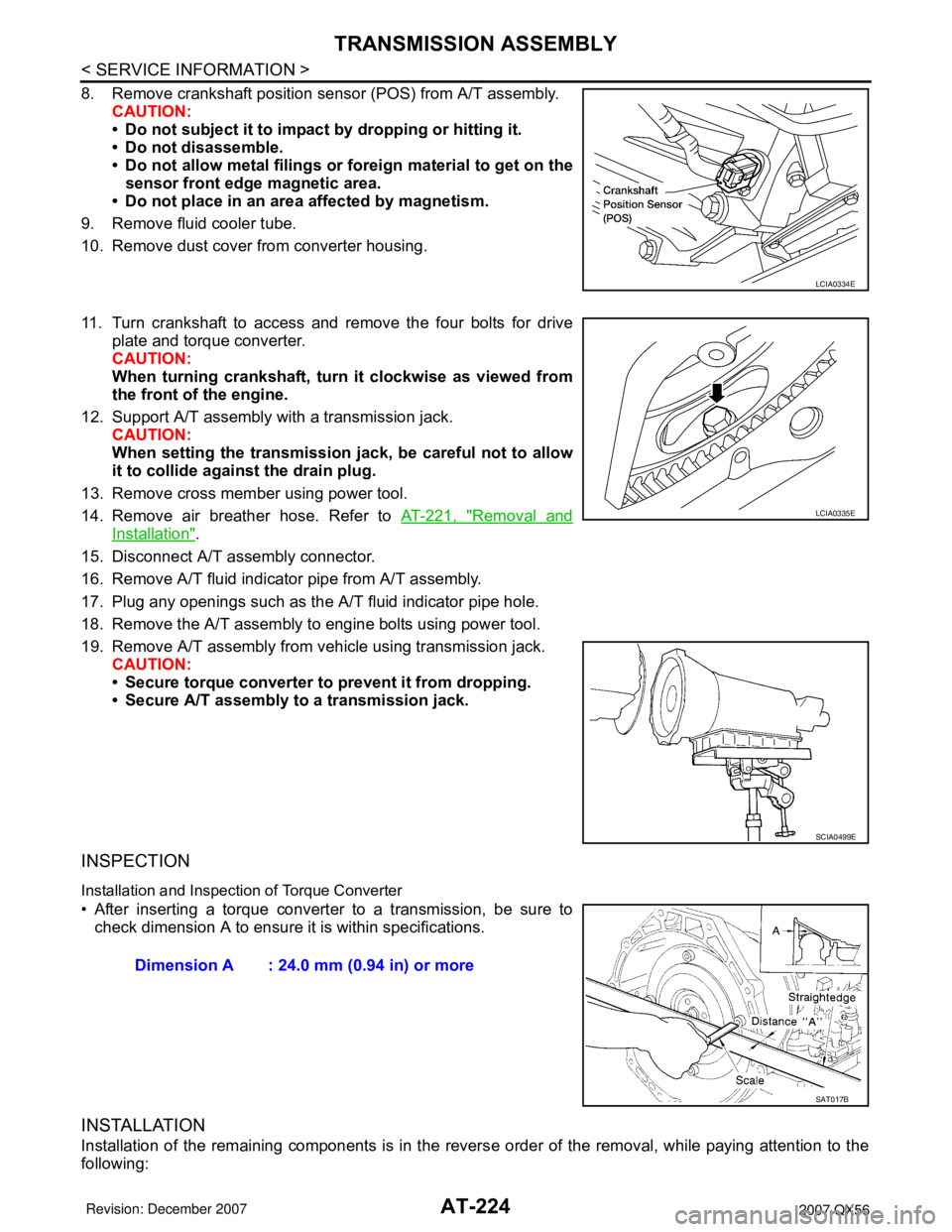
8. Remove crankshaft position sensor (POS) from A/T assembly.
CAUTION:
• Do not subject it to impact by dropping or hitting it.
• Do not disassemble.
• Do not allow metal filings or foreign material to get on the
sensor front edge magnetic area.
• Do not place in an area affected by magnetism.
9. Remove fluid cooler tube.
10. Remove dust cover from converter housing.
11. Turn crankshaft to access and remove the four bolts for drive
plate and torque converter.
CAUTION:
When turning crankshaft, turn it clockwise as viewed from
the front of the engine.
12. Support A/T assembly with a transmission jack.
CAUTION:
When setting the transmission jack, be careful not to allow
it to collide against the drain plug.
13. Remove cross member using power tool.
14. Remove air breather hose. Refer to AT-221, "
Removal and
Installation".
15. Disconnect A/T assembly connector.
16. Remove A/T fluid indicator pipe from A/T assembly.
17. Plug any openings such as the A/T fluid indicator pipe hole.
18. Remove the A/T assembly to engine bolts using power tool.
19. Remove A/T assembly from vehicle using transmission jack.
CAUTION:
• Secure torque converter to prevent it from dropping.
• Secure A/T assembly to a transmission jack.
INSPECTION
Installation and Inspection of Torque Converter
• After inserting a torque converter to a transmission, be sure to
check dimension A to ensure it is within specifications.
INSTALLATION
Installation of the remaining components is in the reverse order of the removal, while paying attention to the
following:
LCIA0334E
LCIA0335E
SCIA0499E
Dimension A : 24.0 mm (0.94 in) or more
SAT017B
Page 295 of 3061

TRANSMISSION ASSEMBLY
AT-225
< SERVICE INFORMATION >
D
E
F
G
H
I
J
K
L
MA
B
AT
N
O
P
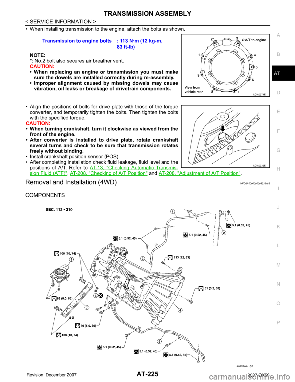
• When installing transmission to the engine, attach the bolts as shown.
NOTE:
*: No.2 bolt also secures air breather vent.
CAUTION:
• When replacing an engine or transmission you must make
sure the dowels are installed correctly during re-assembly.
• Improper alignment caused by missing dowels may cause
vibration, oil leaks or breakage of drivetrain components.
• Align the positions of bolts for drive plate with those of the torque
converter, and temporarily tighten the bolts. Then tighten the bolts
with the specified torque.
CAUTION:
• When turning crankshaft, turn it clockwise as viewed from the
front of the engine.
• After converter is installed to drive plate, rotate crankshaft
several turns and check to be sure that transmission rotates
freely without binding.
• Install crankshaft position sensor (POS).
• After completing installation check fluid leakage, fluid level and the
positions of A/T. Refer to AT-13, "
Checking Automatic Transmis-
sion Fluid (ATF)", AT-208, "Checking of A/T Position" and AT-208, "Adjustment of A/T Position".
Removal and Installation (4WD)INFOID:0000000003532482
COMPONENTS
Transmission to engine bolts : 113 N·m (12 kg-m,
83 ft-lb)
LCIA0371E
LCIA0335E
AWDIA0441GB
Page 297 of 3061

TRANSMISSION ASSEMBLY
AT-227
< SERVICE INFORMATION >
D
E
F
G
H
I
J
K
L
MA
B
AT
N
O
P
17. Plug any openings such as the fluid charging pipe hole.
18. Remove A/T assembly to engine bolts using power tool.
19. Remove A/T assembly with transfer from vehicle.
CAUTION:
• Secure torque converter to prevent it from dropping.
• Secure A/T assembly to transmission jack.
20. Remove transfer from A/T assembly. Refer to TF-128, "
Removal and Installation".
INSPECTION
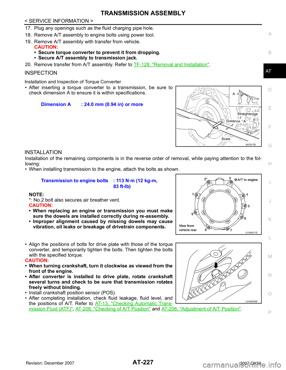
Installation and Inspection of Torque Converter
• After inserting a torque converter to a transmission, be sure to
check dimension A to ensure it is within specifications.
INSTALLATION
Installation of the remaining components is in the reverse order of removal, while paying attention to the fol-
lowing:
• When installing transmission to the engine, attach the bolts as shown.
NOTE:
*: No.2 bolt also secures air breather vent.
CAUTION:
• When replacing an engine or transmission you must make
sure the dowels are installed correctly during re-assembly.
• Improper alignment caused by missing dowels may cause
vibration, oil leaks or breakage of drivetrain components.
• Align the positions of bolts for drive plate with those of the torque
converter, and temporarily tighten the bolts. Then tighten the bolts
with the specified torque.
CAUTION:
• When turning crankshaft, turn it clockwise as viewed from the
front of the engine.
• After converter is installed to drive plate, rotate crankshaft
several turns and check to be sure that transmission rotates
freely without binding.
• Install crankshaft position sensor (POS).
• After completing installation, check fluid leakage, fluid level, and
the positions of A/T. Refer to AT-13, "
Checking Automatic Trans-
mission Fluid (ATF)", AT-208, "Checking of A/T Position" and AT-208, "Adjustment of A/T Position". Dimension A : 24.0 mm (0.94 in) or more
SAT017B
Transmission to engine bolts : 113 N·m (12 kg-m,
83 ft-lb)
LCIA0371E
LCIA0335E
Page 379 of 3061

PRECAUTIONSATC-9
< SERVICE INFORMATION >
C
DE
F
G H
I
K L
M A
B
AT C
N
O P
Precaution for Service of CompressorINFOID:0000000003533224
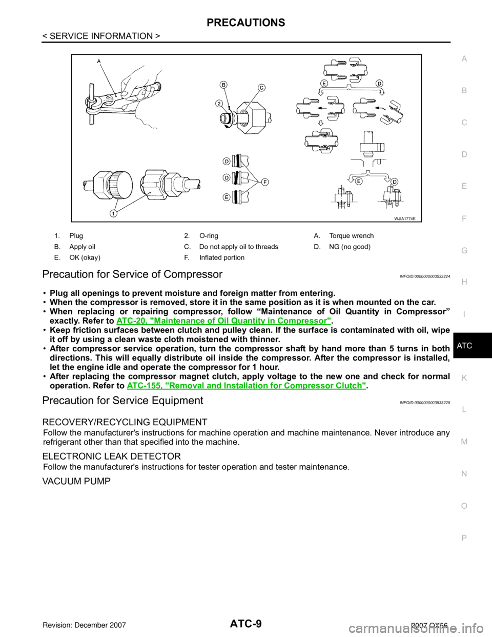
• Plug all openings to prevent moisture and foreign matter from entering.
• When the compressor is removed, store it in the same position as it is when mounted on the car.
• When replacing or repairing co mpressor, follow “Maintenance of Oil Quantity in Compressor”
exactly. Refer to ATC-20, "
Maintenance of Oil Quantity in Compressor".
• Keep friction surfaces between clutch and pulley clean . If the surface is contaminated with oil, wipe
it off by using a clean wast e cloth moistened with thinner.
• After compressor service operation, turn the compressor shaft by hand more than 5 turns in both
directions. This will equa lly distribute oil inside the compresso r. After the compressor is installed,
let the engine idle and oper ate the compressor for 1 hour.
• After replacing the compressor magnet clutch, ap ply voltage to the new one and check for normal
operation. Refer to ATC-155, "
Removal and Installation for Compressor Clutch".
Precaution for Service EquipmentINFOID:0000000003533225
RECOVERY/RECYCLING EQUIPMENT
Follow the manufacturer's instructions for machine operation and machine maintenance. Never introduce any
refrigerant other than that specified into the machine.
ELECTRONIC LEAK DETECTOR
Follow the manufacturer's instructions fo r tester operation and tester maintenance.
VACUUM PUMP
1. Plug 2. O-ring A. Torque wrench
B. Apply oil C. Do not apply oil to threads D. NG (no good)
E. OK (okay) F. Inflated portion
WJIA1774E
Page 390 of 3061

ATC-20
< SERVICE INFORMATION >
OIL
OIL
Maintenance of Oil Quantity in CompressorINFOID:0000000003533232
The oil in the compressor circulates through the system with the refrigerant. Add oil to compressor when
replacing any component or after a large refrigerant leakage has occurred. It is important to maintain the spec-
ified amount.
If oil quantity is not maintained properly, the following malfunctions may result:
• Lack of oil: May lead to a seized compressor
• Excessive oil: Inadequate cooling (thermal exchange interference)
OIL
Name: NISSAN A/C System Oil Type S or equivalent
CHECKING AND ADJUSTING
CAUTION:
If excessive oil leakage is noted, do no t perform the oil return operation.
Start the engine and set the following conditions:
Test Condition
• Engine speed: Idling to 1,200 rpm
• A/C switch: On
• Blower fan speed: MAX position
• Temp. control: Optional [Set so that intake air temperature is 25 ° to 30 ° C (77 ° to 86 °F)]
• Intake position: Recirculation ( )
• Perform oil return operation for about ten minutes
Adjust the oil quantity according to the following table.
Oil Adjusting Procedure for Components Replacement Except Compressor
After replacing any of the following major component s, add the correct amount of oil to the system.
Amount of oil to be added :
• *1: If refrigerant leak is small, no addition of oil is needed.
Oil Adjustment Procedure for Compressor Replacement
Part replaced Oil to be added to system
Remarks
Amount of oil
m (US fl oz, Imp fl oz)
Front evaporator 75 (2.5, 2.6) —
Rear evaporator 75 (2.5, 2.6) —
Condenser 75 (2.5, 2.6) —
Liquid tank 5 (0.2, 0.2) Add if compressor is not replaced.
In case of refrigerant leak 30 (1.0, 1.1) Large leak
— Small leak *1