stop start INFINITI QX56 2007 Factory Owners Manual
[x] Cancel search | Manufacturer: INFINITI, Model Year: 2007, Model line: QX56, Model: INFINITI QX56 2007Pages: 3061, PDF Size: 64.56 MB
Page 1810 of 3061
EM-40
< SERVICE INFORMATION >
TIMING CHAIN
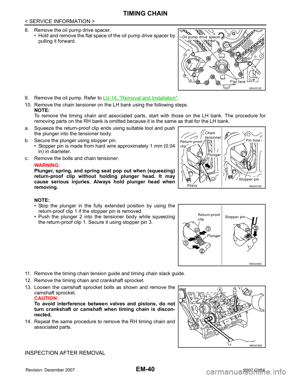
8. Remove the oil pump drive spacer.• Hold and remove the flat space of the oil pump drive spacer bypulling it forward.
9. Remove the oil pump. Refer to LU-14, "
Removal and Installation".
10. Remove the chain tensioner on the LH bank using the following steps. NOTE:
To remove the timing chain and associated parts, start with those on the LH bank. The procedure for
removing parts on the RH bank is omitted because it is the same as that for the LH bank.
a. Squeeze the return-proof clip ends using suitable tool and push the plunger into the tensioner body.
b. Secure the plunger using stopper pin. • Stopper pin is made from hard wire approximately 1 mm (0.04
in) in diameter.
c. Remove the bolts and chain tensioner.
WARNING:
Plunger, spring, and spring seat pop out when (squeezing)
return-proof clip without holding plunger head. It may
cause serious injuries. Alw ays hold plunger head when
removing.
NOTE:
• Stop the plunger in the fully extended position by using the return-proof clip 1 if the stopper pin is removed.
• Push the plunger 2 into the tensioner body while squeezing
the return-proof clip 1. Secure it using stopper pin 3.
11. Remove the timing chain tension guide and timing chain slack guide.
12. Remove the timing chain and crankshaft sprocket.
13. Loosen the camshaft sprocket bolts as shown and remove the camshaft sprocket.
CAUTION:
To avoid interference between valves and pistons, do not
turn crankshaft or camshaft wh en timing chain is discon-
nected.
14. Repeat the same procedure to remove the RH timing chain and associated parts.
INSPECTION AFTER REMOVAL
KBIA2512E
KBIA2479E
KBIA2483E
WBIA0799E
Page 1826 of 3061
EM-56
< SERVICE INFORMATION >
CAMSHAFT
2. Perform the following procedure so as to prevent the engine from being unintentionally started while
checking.
a. Release fuel pressure. Refer to EC-80, "
Fuel Pressure Check".
b. Disconnect ignition coil and injector harness connectors if practical.
3. Remove IVT control solenoid valve.
4. Crank engine, and then make sure that engine oil comes out from IVT control cover oil hole. End cranking
after checking.
WARNING:
Be careful not to touch rotating parts (drive be lts, idler pulley, and crankshaft pulley, etc.).
CAUTION:
• Engine oil may squirt from IVT control soleno id valve installation hole during cranking. Use a
shop cloth to prevent engine oil from splashin g on worker, engine components and vehicle.
• Do not allow engine oil to get on rubber compon ents such as drive belts or engine mount insula-
tors. Immediately wipe off any splashed engine oil.
5. Clean oil groove between oil strainer and IVT control solenoid valve if engine oil does not come out from IVT control valve cover oil hole. Refer to LU-7, "
Schematic".
6. Remove components between IVT control solenoid va lve and camshaft sprocket (INT), and then check
each oil groove for clogging.
• Clean oil groove if necessary.
7. After inspection, installation of the remaining components is in the reverse order of removal.
Valve ClearanceINFOID:0000000003531536
INSPECTION
NOTE:
Perform the following inspection after removal, installation or replacement of camshaft or valve-related parts,
or if there are unusual engine conditions due to changes in valve clearance over time (starting, idling, and/or
noise).
1. Warm up the engine. Then stop the engine.
2. Remove the engine cover and. Refer to EM-12, "
Removal and Installation".
3. Remove the battery cover. Refer to SC-8, "
Removal and Installation".
4. Remove the air cleaner and air duct assembly EM-15, "
Removal and Installation".
5. Remove the RH bank and LH bank rocker covers using power tool. Refer to EM-35, "
Removal and Instal-
lation".
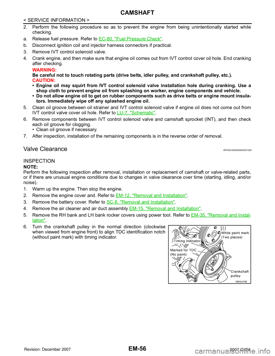
6. Turn the crankshaft pulley in the normal direction (clockwise when viewed from engine front) to align TDC identification notch
(without paint mark) with timing indicator.
KBIA2476E
Page 1834 of 3061

EM-64
< SERVICE INFORMATION >
CYLINDER HEAD
CYLINDER HEAD
On-Vehicle ServiceINFOID:0000000003531540
CHECKING COMPRESSION PRESSURE
1. Warm up the engine thoroughly. Then stop the engine.
2. Release the fuel pressure. Refer to EC-80, "
Fuel Pressure Check".
CAUTION:
If CONSULT-II is not used to release fuel pressure leave the fu el pump fuse disconnected until
step 7.
3. Remove the spark plug from each cylinder. Refer to EM-29, "
Removal and Installation".
4. Connect the engine tachometer (not required in use of CONSULT-II).
5. Install the compression tester with Tool into the spark plug hole.
6. With the accelerator pedal fully depressed, turn the ignition switch to “START” for cranking. When the gauge pointer stabi-
lizes, read the compression pressure and engine rpm. Perform
these steps to check each cylinder.
Unit: kPa (kg/cm2, psi) /rpm
CAUTION:
Always use a fully charged battery to obtain specified engine speed.
• If the engine speed is out of the specified range, che ck the battery liquid for proper gravity. Check the
engine speed again with normal battery gravity.
• If the compression pressure is below the minimum value, check the valve clearances and parts associ- ated with the combustion chamber (valve, valve seat , piston, piston ring, cylinder bore, cylinder head,
cylinder head gasket). After checking, measure the compression pressure again.
• If some cylinders have low compression pressure, pour a small amount of engine oil into the spark plug hole of the cylinder to re-check it for compression.
- If the added engine oil improves the compression, t he piston rings may be worn out or damaged. Check
the piston rings and replace if necessary.
- If the compression pressure remains at a low level despite the addition of engine oil, the valves may be
malfunctioning. Check the valves for damage. R eplace the valve or valve seat accordingly.
• If two adjacent cylinders have respectively low co mpression pressure and their compression remains
low even after the addition of engine oil, the gaskets may be leaking, or a valve in adjacent cylinders
may be damaged. Inspect and repair as required.
7. Install the components in the reverse order of removal.
8. Start the engine and confirm that it runs smoothly.
9. Perform trouble diagnosis. If DTC appears, erase it. Refer to EC-32
.
Tool number : EG15050500 (J-45402)
Standard Minimum
Deference limit be-
tween cylinders
1,520 (15.5, 220) / 200 1,324 (13.5, 192) / 200 98 (1.0, 14) / 200WBIA0605E
Page 1846 of 3061
EM-76
< SERVICE INFORMATION >
ENGINE ASSEMBLY
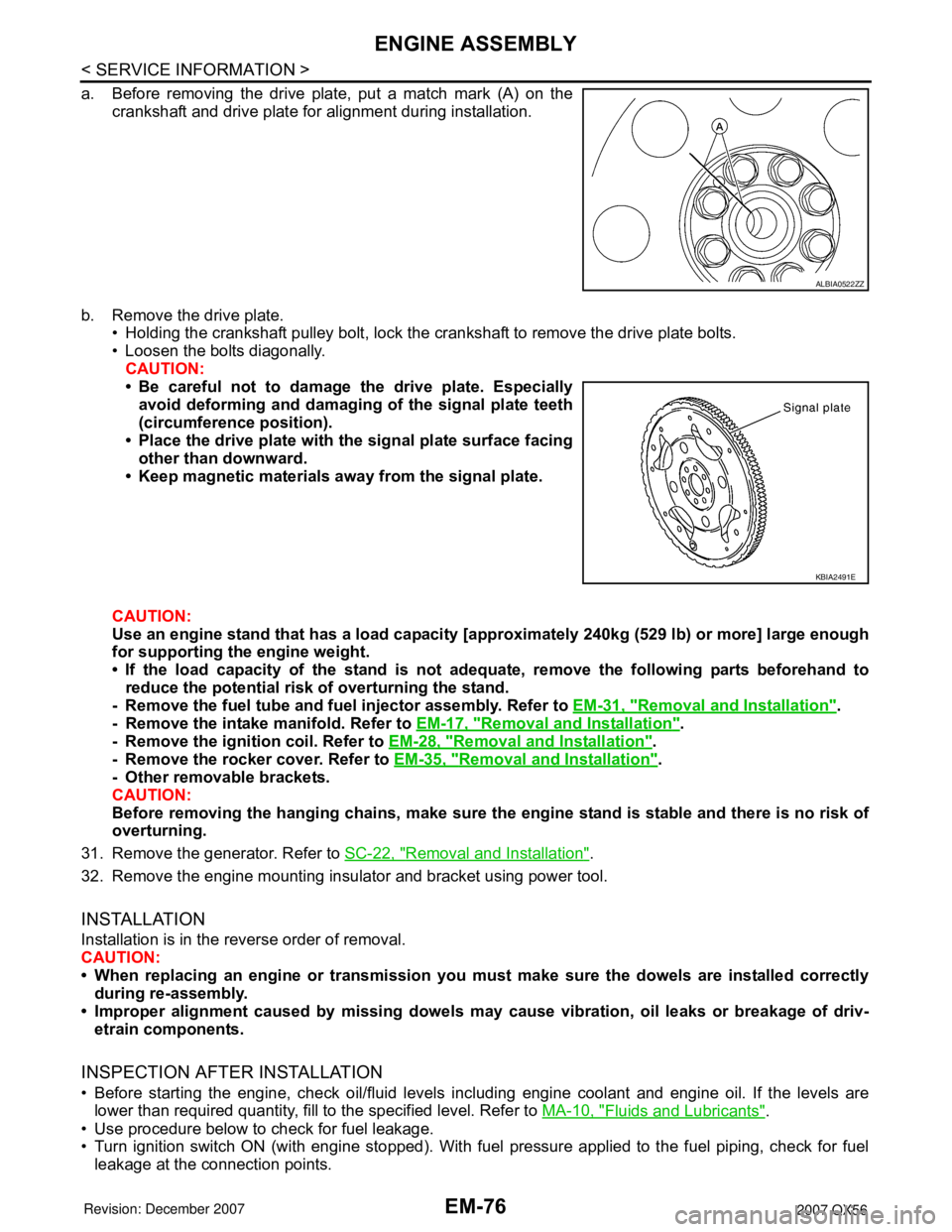
a. Before removing the drive plate, put a match mark (A) on the
crankshaft and drive plate for alignment during installation.
b. Remove the drive plate.
• Holding the crankshaft pulley bolt, lock the crankshaft to remove the drive plate bolts.
• Loosen the bolts diagonally.
CAUTION:
• Be careful not to damage the drive plate. Especially
avoid deforming and damaging of the signal plate teeth
(circumference position).
• Place the drive plate with the signal plate surface facing
other than downward.
• Keep magnetic materials away from the signal plate.
CAUTION:
Use an engine stand that has a load capacity [approximately 240kg (529 lb) or more] large enough
for supporting the engine weight.
• If the load capacity of the stand is not adequate, remove the following parts beforehand to
reduce the potential risk of overturning the stand.
- Remove the fuel tube and fuel injector assembly. Refer to EM-31, "
Removal and Installation".
- Remove the intake manifold. Refer to EM-17, "
Removal and Installation".
- Remove the ignition coil. Refer to EM-28, "
Removal and Installation".
- Remove the rocker cover. Refer to EM-35, "
Removal and Installation".
- Other removable brackets.
CAUTION:
Before removing the hanging chains, make sure the engine stand is stable and there is no risk of
overturning.
31. Remove the generator. Refer to SC-22, "
Removal and Installation".
32. Remove the engine mounting insulator and bracket using power tool.
INSTALLATION
Installation is in the reverse order of removal.
CAUTION:
• When replacing an engine or transmission you must make sure the dowels are installed correctly
during re-assembly.
• Improper alignment caused by missing dowels may cause vibration, oil leaks or breakage of driv-
etrain components.
INSPECTION AFTER INSTALLATION
• Before starting the engine, check oil/fluid levels including engine coolant and engine oil. If the levels are
lower than required quantity, fill to the specified level. Refer to MA-10, "
Fluids and Lubricants".
• Use procedure below to check for fuel leakage.
• Turn ignition switch ON (with engine stopped). With fuel pressure applied to the fuel piping, check for fuel
leakage at the connection points.
ALBIA0522ZZ
KBIA2491E
Page 1847 of 3061
ENGINE ASSEMBLY
EM-77
< SERVICE INFORMATION >
C
D
E
F
G
H
I
J
K
L
MA
EM
N
P O
• Start engine. With engine speed increased, check again for fuel leakage at connection points.
• Run engine to check for unusual noise and vibration.
• Warm up engine thoroughly to make sure there is no leakage of fuel, exhaust gas, or any oils/fluids including
engine oil and engine coolant.
• Bleed air from passages in lines and hoses, such as in cooling system.
• After cooling down the engine, again check oil/fluid levels including engine oil and engine coolant. Refill to
specified level if necessary.
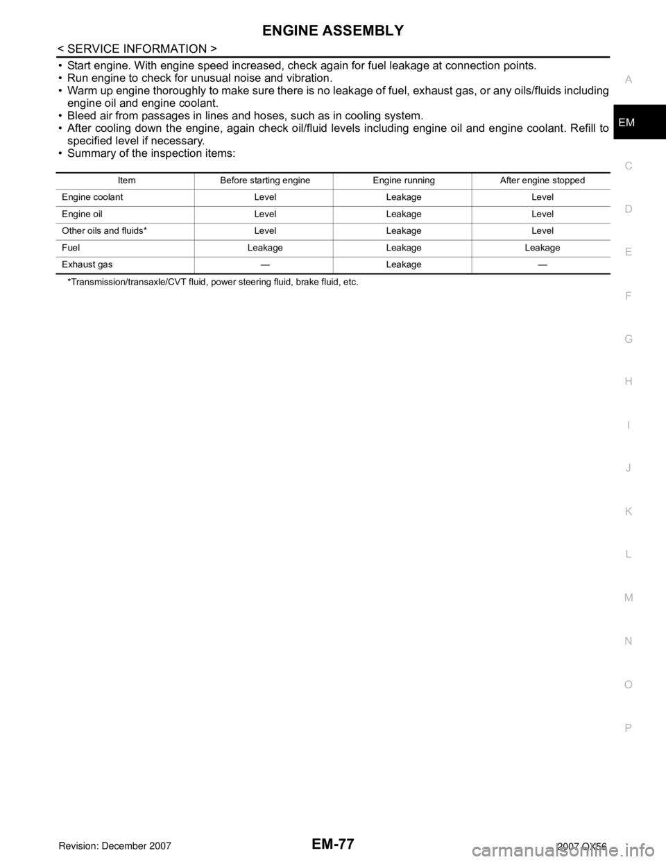
• Summary of the inspection items:
*Transmission/transaxle/CVT fluid, power steering fluid, brake fluid, etc.Item Before starting engine Engine running After engine stopped
Engine coolant Level Leakage Level
Engine oil Level Leakage Level
Other oils and fluids* Level Leakage Level
Fuel Leakage Leakage Leakage
Exhaust gas — Leakage —
Page 1906 of 3061
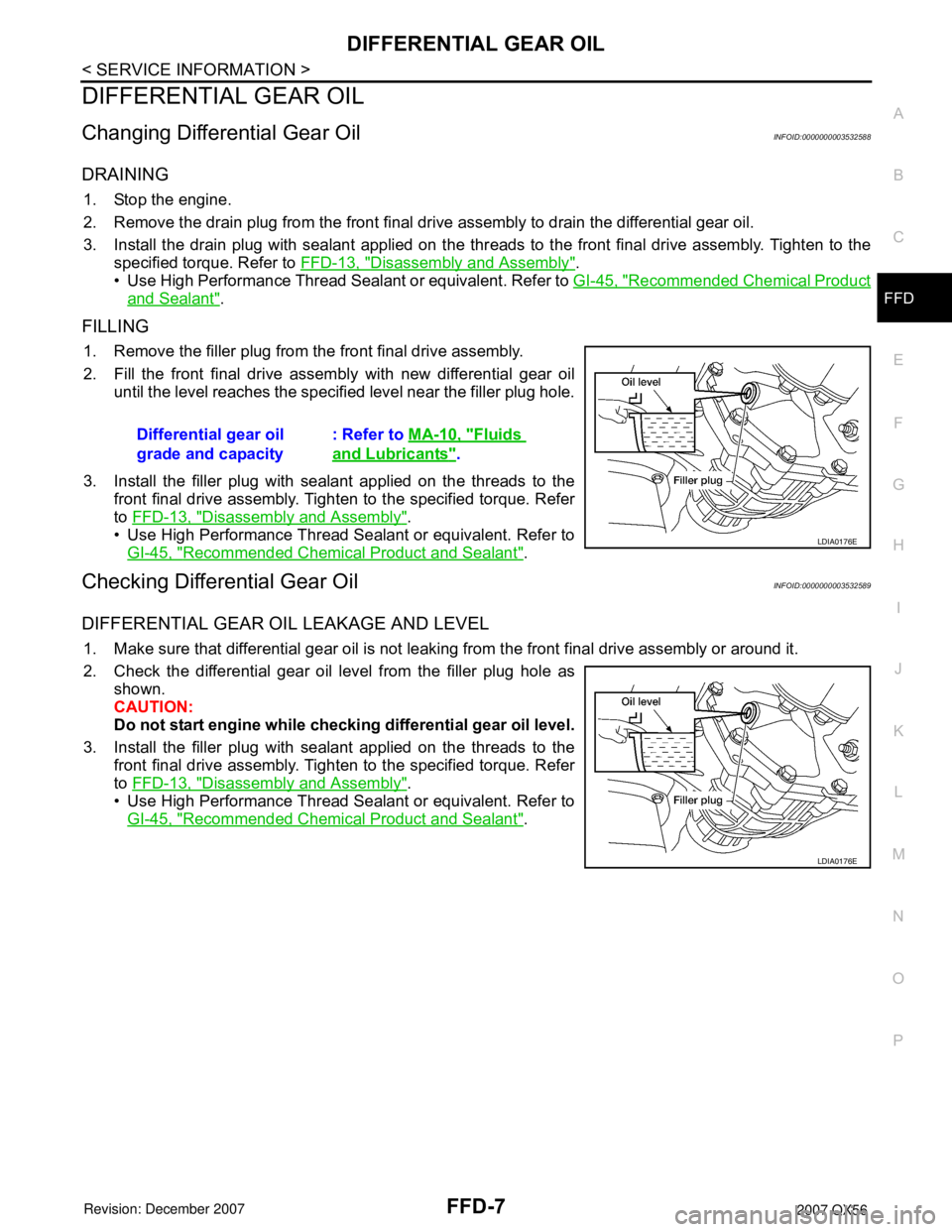
DIFFERENTIAL GEAR OIL
FFD-7
< SERVICE INFORMATION >
C
E
F
G
H
I
J
K
L
MA
B
FFD
N
O
P
DIFFERENTIAL GEAR OIL
Changing Differential Gear OilINFOID:0000000003532588
DRAINING
1. Stop the engine.
2. Remove the drain plug from the front final drive assembly to drain the differential gear oil.
3. Install the drain plug with sealant applied on the threads to the front final drive assembly. Tighten to the
specified torque. Refer to FFD-13, "
Disassembly and Assembly".
• Use High Performance Thread Sealant or equivalent. Refer to GI-45, "
Recommended Chemical Product
and Sealant".
FILLING
1. Remove the filler plug from the front final drive assembly.
2. Fill the front final drive assembly with new differential gear oil
until the level reaches the specified level near the filler plug hole.
3. Install the filler plug with sealant applied on the threads to the
front final drive assembly. Tighten to the specified torque. Refer
to FFD-13, "
Disassembly and Assembly".
• Use High Performance Thread Sealant or equivalent. Refer to
GI-45, "
Recommended Chemical Product and Sealant".
Checking Differential Gear OilINFOID:0000000003532589
DIFFERENTIAL GEAR OIL LEAKAGE AND LEVEL
1. Make sure that differential gear oil is not leaking from the front final drive assembly or around it.
2. Check the differential gear oil level from the filler plug hole as
shown.
CAUTION:
Do not start engine while checking differential gear oil level.
3. Install the filler plug with sealant applied on the threads to the
front final drive assembly. Tighten to the specified torque. Refer
to FFD-13, "
Disassembly and Assembly".
• Use High Performance Thread Sealant or equivalent. Refer to
GI-45, "
Recommended Chemical Product and Sealant". Differential gear oil
grade and capacity: Refer to MA-10, "
Fluids
and Lubricants".
LDIA0176E
LDIA0176E
Page 1935 of 3061

FL-4
< SERVICE INFORMATION >
FUEL SYSTEM
FUEL SYSTEM
Checking Fuel LineINFOID:0000000003532203
Inspect fuel lines, fuel filler cap and fuel tank for improper attach-
ment, leaks, cracks, damage, loose connections, chafing or deterio-
ration.
If necessary, repair or replace damaged parts.
General PrecautionINFOID:0000000003532204
WARNING:
When replacing fuel line parts, be sure to observe the following.
• Put a “CAUTION: INFLAMMABLE” sign in the workshop.
• Be sure to work in a well ventilated area and furnish workshop with a CO
2 fire extinguisher.
• Do not smoke while servicing fuel system. Keep open flames and sparks away from the work area.
CAUTION:
• Before removing fuel line parts, carry out the following procedures:
- Put drained fuel in an explosion-proof container and put the lid on securely. Keep the container in
safe area.
- Release fuel pressure from the fuel lines. Refer to EC-80, "
Fuel Pressure Check" .
- Disconnect the battery negative terminal.
• Always replace O-rings and clamps with new ones.
• Do not kink or twist hoses when they are being installed.
• After connecting the fuel tube quick connectors, make sure
the quick connectors are secure.
Ensure that the connector and resin tube do not contact any
adjacent parts.
• After installing tubes, make sure there is no fuel leakage at
connections in the following steps.
- Apply fuel pressure to fuel lines with turning ignition switch
ON (with engine stopped). Then check for fuel leaks at con-
nections.
- Start the engine and rev it up and check for fuel leaks at con-
nections.
• Use only a Genuine NISSAN fuel filler cap as a replacement. If
an incorrect fuel filler cap is used, the MIL may come on.
• For servicing “Evaporative Emission System” parts, refer to
EC-33
.
• For servicing “On Board Refueling Vapor Recovery (ORVR)”
parts, refer to EC-40
.
SMA803A
PBIC1268E
Page 2026 of 3061

SQUEAK AND RATTLE TROUBLE DIAGNOSIS
GW-7
< SERVICE INFORMATION >
C
D
E
F
G
H
J
K
L
MA
B
GW
N
O
P
SILICONE GREASE
Used instead of UHMW tape that will be visible or not fit.
Note: Will only last a few months.
SILICONE SPRAY
Use when grease cannot be applied.
DUCT TAPE
Use to eliminate movement.
CONFIRM THE REPAIR
Confirm that the cause of a noise is repaired by test driving the vehicle. Operate the vehicle under the same
conditions as when the noise originally occurred. Refer to the notes on the Diagnostic Worksheet.
Generic Squeak and Rattle TroubleshootingINFOID:0000000003533020
Refer to Table of Contents for specific component removal and installation information.
INSTRUMENT PANEL
Most incidents are caused by contact and movement between:
1. The cluster lid A and instrument panel
2. Acrylic lens and combination meter housing
3. Instrument panel to front pillar garnish
4. Instrument panel to windshield
5. Instrument panel mounting pins
6. Wiring harnesses behind the combination meter
7. A/C defroster duct and duct joint
These incidents can usually be located by tapping or moving the components to duplicate the noise or by
pressing on the components while driving to stop the noise. Most of these incidents can be repaired by apply-
ing felt cloth tape or silicone spray (in hard to reach areas). Urethane pads can be used to insulate wiring har-
ness.
CAUTION:
Do not use silicone spray to isolate a squeak or rattle. If you saturate the area with silicone, you will
not be able to recheck the repair.
CENTER CONSOLE
Components to pay attention to include:
1. Shifter assembly cover to finisher
2. A/C control unit and cluster lid C
3. Wiring harnesses behind audio and A/C control unit
The instrument panel repair and isolation procedures also apply to the center console.
DOORS
Pay attention to the:
1. Finisher and inner panel making a slapping noise
2. Inside handle escutcheon to door finisher
3. Wiring harnesses tapping
4. Door striker out of alignment causing a popping noise on starts and stops
Tapping or moving the components or pressing on them while driving to duplicate the conditions can isolate
many of these incidents. You can usually insulate the areas with felt cloth tape or insulator foam blocks from
the NISSAN Squeak and Rattle Kit (J-43980) to repair the noise.
TRUNK
Trunk noises are often caused by a loose jack or loose items put into the trunk by the owner.
In addition look for:
1. Trunk lid bumpers out of adjustment
2. Trunk lid striker out of adjustment
3. The trunk lid torsion bars knocking together
4. A loose license plate or bracket
Page 2037 of 3061
GW-18
< SERVICE INFORMATION >
POWER WINDOW SYSTEM
The signal is transmitted from main power window and door lock/unlock switch to power window and door
lock/unlock switch RH
• Front door window RH operation signal.
• Power window control by front door lock assembly LH (key cylinder switch) signal.
• Power window lock signal.
• Retained power operation signal.
• Rear power window operation.
POWER WINDOW LOCK
The power window lock is designed to lock operation of all windows except for front door window LH.
When in the lock position, the power window lock signal is transmitted to power window and door lock/unlock
switch RH by power window serial link. This prevents the power window motor from operating.
RETAINED POWER OPERATION
When the ignition switch is turned to the OFF position from ON or START position, power is supplied for 45
seconds
• to main power window and door lock/unlock switch terminal 10
• from BCM terminal 68.
When power and ground are supplied, the BCM continues to be energized, and the power window can be
operated.
The retained power operation is canceled when the front LH or front RH door is opened.
Retained power operation period can be changed by CONSULT-II. Refer to GW-31, "
CONSULT-II Function
(BCM)" .
ANTI-PINCH SYSTEM
Main power window and door lock/unlock switch, power window and door lock/unlock switch RH and rear
power window control unit LH and RH monitors the power window motor operation and the power window
position (full closed or other) for each power window by the signals from encoder and limit switch in power win-
dow motor.
When a window switch detects interruption during the following close operation,
• automatic close operation when ignition switch is in the ON position
• automatic close operation during retained power operation
Main power window and door lock/unlock switch, power window and door lock/unlock switch RH and rear
power window control unit LH and RH controls each power window motor for open and the power window will
be lowered about 150 mm (5.91 in).
POWER WINDOW CONTROL BY THE FRONT DOOR LOCK ASSEMBLY LH (KEY CYLINDER
SWITCH)
When ignition key switch is OFF, front power window LH and RH can be opened or closed by turning the front
door lock assembly LH (key cylinder switch) to the UNLOCK/LOCK position for more than 1 second.
• Front power windows can be opened as the front door lock assembly LH (key cylinder switch) is kept fully
turned to the UNLOCK position.
• Front power windows can be closed as the front door lock assembly LH (key cylinder switch) is kept fully
turned to the LOCK position.
• While performing open/close operation for the windows, power window is stopped when the front door lock
assembly LH (key cylinder switch) is placed in the NEUTRAL position.
• When the ignition switch is turned ON while the power window opening operation is performed, the power
window opening stops.
CAN Communication System DescriptionINFOID:0000000003533026
Refer to LAN-4.
Page 2111 of 3061
IDX-7
A
C
D
E
F
G
H
I
J
K
L B
IDX
ALPHABETICAL INDEX
Pressure switch 2 ............................................. AT-153
Pressure switch 3 ............................... AT-137, AT-157
Pressure switch 5 ............................... AT-145, AT-159
Pressure switch 6 ............................... AT-149, AT-161
Pressure test (A/T) ............................................. AT-52
Propeller shaft ........................................... PR-4, PR-8
Propeller shaft inspection .................................. MA-25
Propeller shaft on vehicle service ....................... PR-8
Propeller shaft vibration ............................ PR-4, PR-8
PS/SEN - Wiring diagram ................................ EC-471
R
R/VIEW - Wiring diagram .................................... DI-66
Radiator ............................................................. CO-14
Rear Audio Remote Control Unit ......................... AV-8
Rear axle ........................................................... RAX-5
Rear bumper ....................................................... EI-15
Rear case (Transfer) .......................... TF-148, TF-181
Rear combination lamp removal and installation ... LT-
101
Rear cover packing replacement diff. .............. RFD-28
Rear door ........................................... BL-117, GW-65
Rear seat belt ...................................................... SB-7
Rear suspension ............................................. RSU-23
Rear view monitor ............................................... DI-63
Rear washer .................................................... WW-29
Rear window defogger ..................................... GW-71
Rear wiper ....................................................... WW-29
Refrigerant connection precaution .................... ATC-6
Refrigerant discharging evacuating charging ATC-175
Refrigerant general precaution .......................... ATC-6
Refrigerant lines ........... ATC-175, ATC-183, ATC-184
Refrigerant pressure sensor ............ EC-692, ATC-184
Relay box .......................................................... PG-78
Remote keyless entry system ............................ BL-40
Removal and installation (A/T) ........... AT-238, AT-241
Removal and installation (Transfer) ................. TF-145
Ring gear diff. inspection ................................. RFD-18
Road wheel size ................................................. GI-51
Rocker cover ..................................................... EM-35
Room lamp ....................................................... LT-110
Room lamp - See Interior lamp ........................ LT-110
ROOM/L - Wiring diagram ................................ LT-116
RP/SEN - Wiring diagram ............................... EC-693
S
SAE J1979 - Service $01 - 09 ........................... EC-49
SEAT - Wiring diagram ..................................... SE-81
Seat belt inspection ............................... SB-12, MA-32
Seat belt pre-tensioner .................................... SRS-50
Seat belt, front ..................................................... SB-3
Seat belt, rear ...................................................... SB-7
Seat, front .......................................................... SE-89
Self-diagnosis (Transfer) .................................... TF-49
SEN/PW - Wiring diagram ............................... EC-483
SHIFT - Wiring diagram ................................... AT-217
Shift control (Transfer) ....................... TF-149, TF-176
Shift lock system .............................................. AT-216
Shock absorber (front) ..................................... FSU-11
Shock absorber (rear) ..................................... RSU-32
Side air bag (satellite) sensor .......................... SRS-49
Side curtain air bag .......................................... SRS-46
Side trim .............................................................. EI-35
SMJ (super multiple junction) ............................ PG-74
SONAR - Wiring diagram ................................... DI-53
Spare tire size ..................................................... GI-51
Spark plug ......................................................... EM-29
Specification value ........................................... EC-139
Speedometer ........................................................ DI-5
Spiral cable ...................................................... SRS-41
SROOF - Wiring diagram .................................. RF-13
SRS - See Supplemental Restraint System ...... SRS-5
SRS - Wiring diagram ...................................... SRS-13
SRS Trouble diagnoses ..................................... SRS-9
Stabilizer bar (front) ......................................... FSU-12
Stabilizer bar (rear) ......................................... RSU-39
Stall test (A/T) .................................................... AT-51
Standardized relay ............................................. PG-72
START - Wiring diagram ................................... SC-11
Starting system .................................................. SC-10
Steering gear, linkage and transfer gear inspection .....
MA-29
Steering linkage ................................................. PS-15
Steering wheel and column ................................. PS-7
Step lamp ......................................................... LT-111
Stop lamp ........................................................... LT-84
Stop lamp switch ................. EC-572, EC-584, EC-647
STOP/L - Wiring diagram ................................... LT-85
Strut (front) ...................................................... FSU-10
STSIG - Wiring diagram .................................... AT-97
Sub-oil pump (Transfer) ...................... TF-154, TF-167
Sun gear (Transfer) ............................ TF-149, TF-176
Sun roof, electric ................................................ RF-10
Sunload sensor .............................................. ATC-144
Sunroof .............................................................. RF-22
Supplemental Restraint System ........................ SRS-5
Supplemental restraint system - Wiring diagram . SRS-
13
Symbols and abbreviations ..................... GI-10, GI-23
Symptom matrix chart ........................................ EC-94
System readiness test (SRT) code .................... EC-55
T
Tachometer .......................................................... DI-5
Tail lamp ............................................................. LT-89
TAIL/L - Wiring diagram ...................................... LT-91
TCM circuit diagram .......................................... AT-50
TCS - Wiring diagram ..................................... BRC-16
TCS (traction control system) ........................... BRC-7
TCS component parts and connector location BRC-14
TCS wheel sensors ........................................ BRC-14
Telephone .......................................................... AV-62
Theft warning system - See Vehicle security (Theft warn-
ing) system ......................................................... BL-67
Thermometer ...................................................... DI-23