key INFINITI QX56 2007 Factory Service Manual
[x] Cancel search | Manufacturer: INFINITI, Model Year: 2007, Model line: QX56, Model: INFINITI QX56 2007Pages: 3061, PDF Size: 64.56 MB
Page 1976 of 3061
GI-10
< SERVICE INFORMATION >
HOW TO USE THIS MANUAL
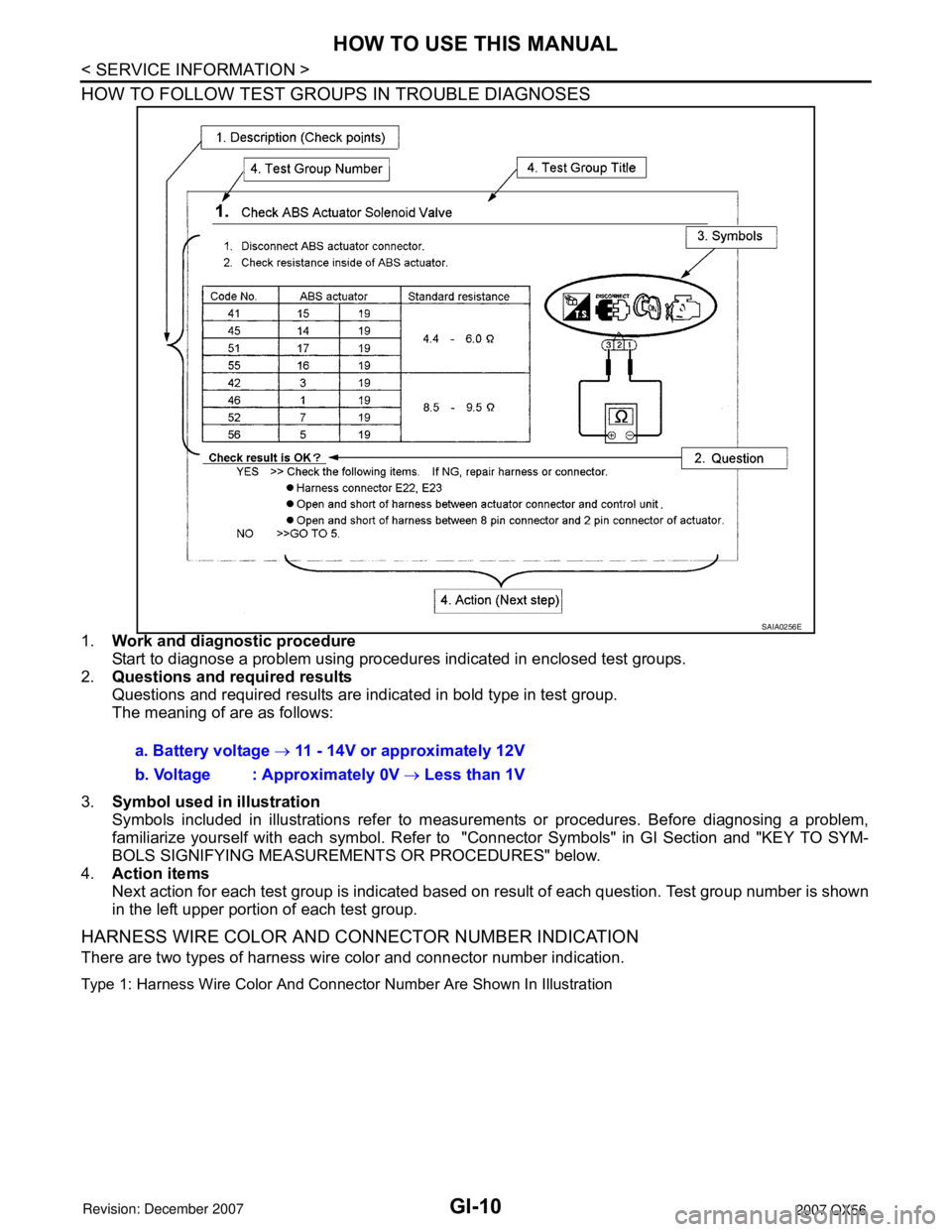
HOW TO FOLLOW TEST GROUPS IN TROUBLE DIAGNOSES
1.Work and diagnostic procedure
Start to diagnose a problem using procedures indicated in enclosed test groups.
2.Questions and required results
Questions and required results are indicated in bold type in test group.
The meaning of are as follows:
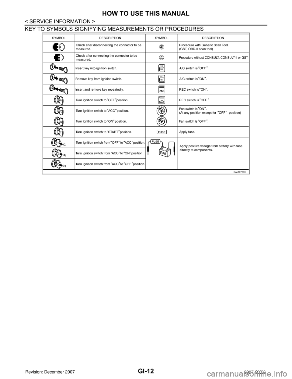
3.Symbol used in illustration
Symbols included in illustrations refer to measurements or procedures. Before diagnosing a problem,
familiarize yourself with each symbol. Refer to "Connector Symbols" in GI Section and "KEY TO SYM-
BOLS SIGNIFYING MEASUREMENTS OR PROCEDURES" below.
4.Action items
Next action for each test group is indicated based on result of each question. Test group number is shown
in the left upper portion of each test group.
HARNESS WIRE COLOR AND CONNECTOR NUMBER INDICATION
There are two types of harness wire color and connector number indication.
Type 1: Harness Wire Color And Connector Number Are Shown In Illustration
SAIA0256E
a. Battery voltage → 11 - 14V or approximately 12V
b. Voltage : Approximately 0V → Less than 1V
Page 1978 of 3061
GI-12
< SERVICE INFORMATION >
HOW TO USE THIS MANUAL
KEY TO SYMBOLS SIGNIFYING MEASUREMENTS OR PROCEDURES
SAIA0750E
Page 1991 of 3061
SERVICE INFORMATION FOR ELECTRICAL INCIDENT
GI-25
< SERVICE INFORMATION >
C
D
E
F
G
H
I
J
K
L
MB
GI
N
O
P
How to Perform Efficient Diagnosis for an Electrical IncidentINFOID:0000000003531488
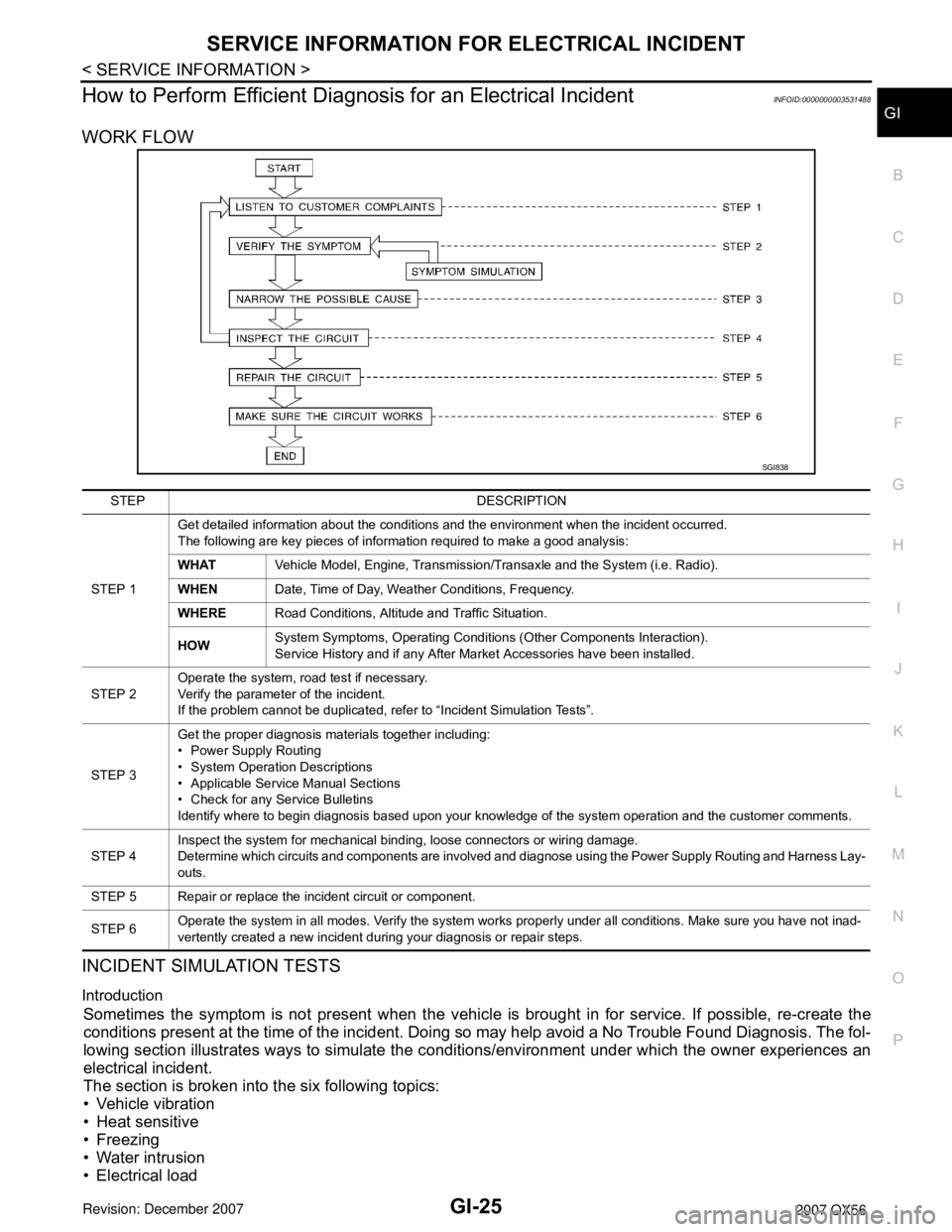
WORK FLOW
INCIDENT SIMULATION TESTS
Introduction
Sometimes the symptom is not present when the vehicle is brought in for service. If possible, re-create the
conditions present at the time of the incident. Doing so may help avoid a No Trouble Found Diagnosis. The fol-
lowing section illustrates ways to simulate the conditions/environment under which the owner experiences an
electrical incident.
The section is broken into the six following topics:
• Vehicle vibration
• Heat sensitive
• Freezing
• Water intrusion
• Electrical load
SGI838
STEP DESCRIPTION
STEP 1Get detailed information about the conditions and the environment when the incident occurred.
The following are key pieces of information required to make a good analysis:
WHATVehicle Model, Engine, Transmission/Transaxle and the System (i.e. Radio).
WHENDate, Time of Day, Weather Conditions, Frequency.
WHERERoad Conditions, Altitude and Traffic Situation.
HOWSystem Symptoms, Operating Conditions (Other Components Interaction).
Service History and if any After Market Accessories have been installed.
STEP 2Operate the system, road test if necessary.
Verify the parameter of the incident.
If the problem cannot be duplicated, refer to “Incident Simulation Tests”.
STEP 3Get the proper diagnosis materials together including:
• Power Supply Routing
• System Operation Descriptions
• Applicable Service Manual Sections
• Check for any Service Bulletins
Identify where to begin diagnosis based upon your knowledge of the system operation and the customer comments.
STEP 4Inspect the system for mechanical binding, loose connectors or wiring damage.
Determine which circuits and components are involved and diagnose using the Power Supply Routing and Harness Lay-
outs.
STEP 5 Repair or replace the incident circuit or component.
STEP 6Operate the system in all modes. Verify the system works properly under all conditions. Make sure you have not inad-
vertently created a new incident during your diagnosis or repair steps.
Page 1995 of 3061
SERVICE INFORMATION FOR ELECTRICAL INCIDENT
GI-29
< SERVICE INFORMATION >
C
D
E
F
G
H
I
J
K
L
MB
GI
N
O
P
• Close the relay and probe at the solenoid.
voltage; open is further down the circuit than the solenoid.
no voltage; open is between relay and solenoid (point C).
Any powered circuit can be diagnosed using the approach in the previous example.
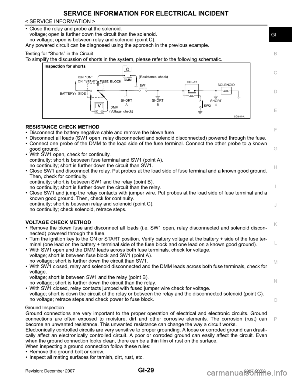
Testing for “Shorts” in the Circuit
To simplify the discussion of shorts in the system, please refer to the following schematic.
RESISTANCE CHECK METHOD
• Disconnect the battery negative cable and remove the blown fuse.
• Disconnect all loads (SW1 open, relay disconnected and solenoid disconnected) powered through the fuse.
• Connect one probe of the DMM to the load side of the fuse terminal. Connect the other probe to a known
good ground.
• With SW1 open, check for continuity.
continuity; short is between fuse terminal and SW1 (point A).
no continuity; short is further down the circuit than SW1.
• Close SW1 and disconnect the relay. Put probes at the load side of fuse terminal and a known good ground.
Then, check for continuity.
continuity; short is between SW1 and the relay (point B).
no continuity; short is further down the circuit than the relay.
• Close SW1 and jump the relay contacts with jumper wire. Put probes at the load side of fuse terminal and a
known good ground. Then, check for continuity.
continuity; short is between relay and solenoid (point C).
no continuity; check solenoid, retrace steps.
VOLTAGE CHECK METHOD
• Remove the blown fuse and disconnect all loads (i.e. SW1 open, relay disconnected and solenoid discon-
nected) powered through the fuse.
• Turn the ignition key to the ON or START position. Verify battery voltage at the battery + side of the fuse ter-
minal (one lead on the battery + terminal side of the fuse block and one lead on a known good ground).
• With SW1 open and the DMM leads across both fuse terminals, check for voltage.
voltage; short is between fuse block and SW1 (point A).
no voltage; short is further down the circuit than SW1.
• With SW1 closed, relay and solenoid disconnected and the DMM leads across both fuse terminals, check for
voltage.
voltage; short is between SW1 and the relay (point B).
no voltage; short is further down the circuit than the relay.
• With SW1 closed, relay contacts jumped with fused jumper wire check for voltage.
voltage; short is down the circuit of the relay or between the relay and the disconnected solenoid (point C).
no voltage; retrace steps and check power to fuse block.
Ground Inspection
Ground connections are very important to the proper operation of electrical and electronic circuits. Ground
connections are often exposed to moisture, dirt and other corrosive elements. The corrosion (rust) can
become an unwanted resistance. This unwanted resistance can change the way a circuit works.
Electronically controlled circuits are very sensitive to proper grounding. A loose or corroded ground can drasti-
cally affect an electronically controlled circuit. A poor or corroded ground can easily affect the circuit. Even
when the ground connection looks clean, there can be a thin film of rust on the surface.
When inspecting a ground connection follow these rules:
• Remove the ground bolt or screw.
• Inspect all mating surfaces for tarnish, dirt, rust, etc.
SGI847-A
Page 2001 of 3061

CONSULT-II CHECKING SYSTEM
GI-35
< SERVICE INFORMATION >
C
D
E
F
G
H
I
J
K
L
MB
GI
N
O
PCONSULT-II CHECKING SYSTEM
DescriptionINFOID:0000000003531490
• CONSULT-II is a hand-held type tester. When it is connected with a diagnostic connector equipped on the
vehicle side, it will communicate with the control unit equipped in the vehicle and then enable various kinds
of diagnostic tests.
• Refer to “CONSULT-II Software Operation Manual” for more information.
Function and System ApplicationINFOID:0000000003531491
x: Applicable.
*1: If equipped.Diagnostic test mode Function
ENGINE
A/T
ICC
*1
ABS
AIR BAG
IPDM E/R
BCM
AUTO DRIVE POS.
REARVIEW CAMERA
AIR LEVELIZER
ALL MODE AWD/4WD
HVAC
NVIS (NATS)
*2
NVIS (NATS BCM OR S/ENT)
*2
Work supportThis mode enables a technician to adjust some devices
faster and more accurately by following the indications on
CONSULT-II.xxxx - - xxxxx - - -
Self-diagnostic Self-diagnostic can be performed quickly. ----x---------
Self-diagnostic results Self-diagnostic results can be read and erased quickly. xxxx - xxx - xxxxx
Trouble diagnostic
recordCurrent self-diagnostic results and all trouble diagnostic
records previously stored can be read.--- - x---------
Data monitor Input/Output data in the ECM can be read. xxxx - x - xxxxx - -
Data monitor (spec) Data monitor specification can be read. x-------------
CAN diagnosis support
monitorThe communication condition of CAN communication line
can be read.xxxx - xxx - - xx - -
Active testDiagnostic Test Mode in which CONSULT-II drives some
actuators apart from the ECMs and also shifts some param-
eters in a specified range.x-xx-x-x-x----
Function testThis mode can show results of self-diagnosis of ECU with
either “OK” or “NG”. For engines, more practical tests re-
garding sensors/switches and/or actuators are available.xx-xx- --- -----
DTC & SRT confirma-
tionThe results of SRT (System Readiness Test) and the self-
diagnosis status/result can be confirmed.x-------------
DTC work supportThe operating condition to confirm Diagnosis Trouble
Codes can be selected.xx------------
ECM/ECU part number ECM/ECU part number can be read.
xxxx - -xx
xxxx - -
ECU discriminated No.Classification number of a replacement ECU can be read to
prevent an incorrect ECU from being installed.----x---------
Passenger Airbag Displays the STATUS (readiness) of the front passenger air
bag.----x---------
Configuration Sets control module parameters to match vehicle options. ------x-------
PIN read
*3This mode shows the BCM-specific 5-digit code. -------------x
Control unit
initialization
*3All registered ignition key IDs in NATS components can be
initialized and new IDs can be registered.------------x-
Page 2008 of 3061
GI-42
< SERVICE INFORMATION >
TOW TRUCK TOWING
TOW TRUCK TOWING
Tow Truck TowingINFOID:0000000003531499
WARNING:
• Never get under the vehicle while it is supported only by the jack. Always use safety stands to sup-
port the frame when you have to get under the vehicle.
• Place wheel chocks at both front and back of the wheels on the ground.
CAUTION:
• All applicable State or Provincial (in Canada) laws and local laws regarding the towing operation
must be obeyed.
• It is necessary to use proper towing equipment to avoid possible damage during towing operation.
Towing is in accordance with Towing Procedure Manual at dealer.
• Always attach safety chains before towing.
• When towing, make sure that the transmission, steering system and powertrain are in good order. If
any unit is damaged, dollies must be used.
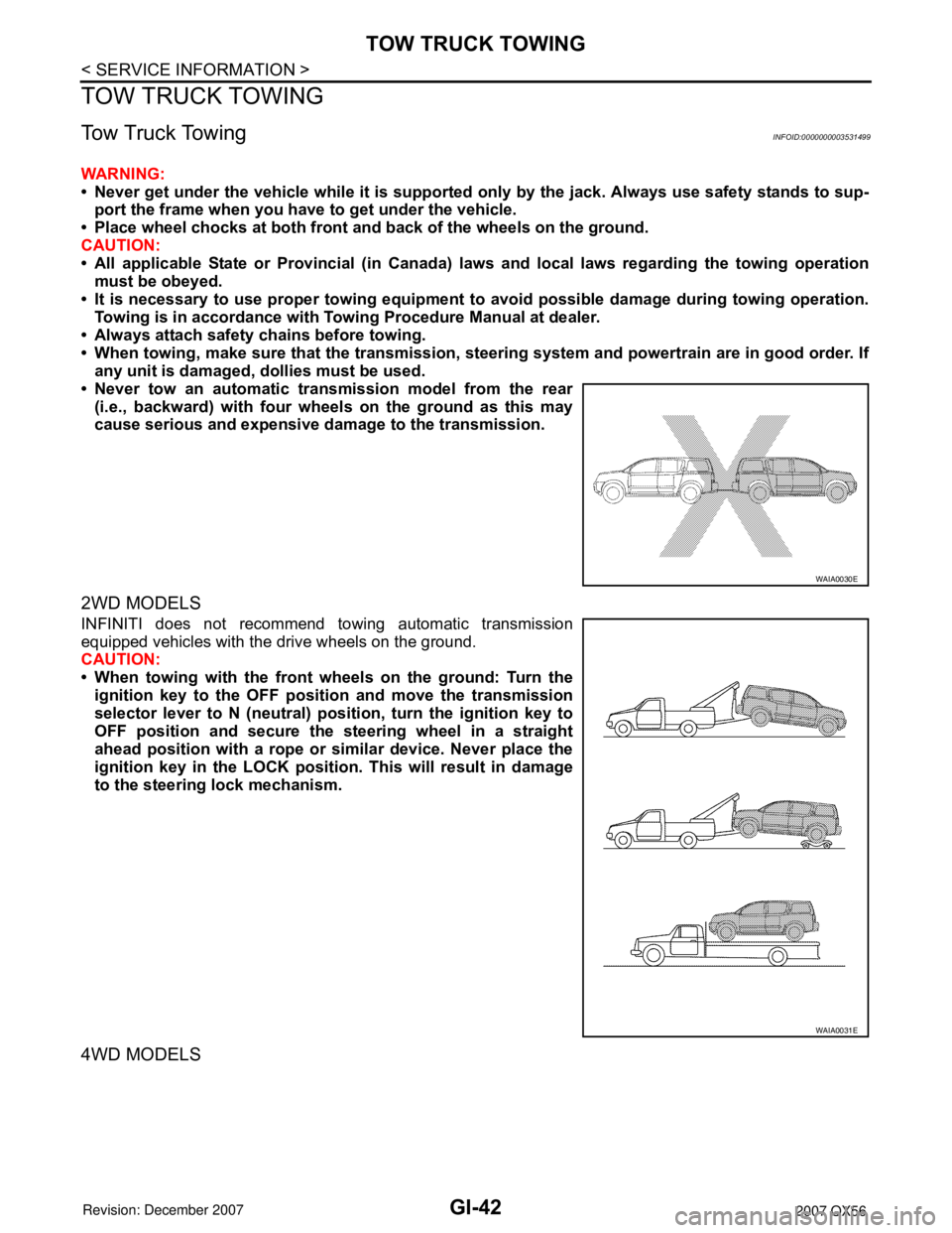
• Never tow an automatic transmission model from the rear
(i.e., backward) with four wheels on the ground as this may
cause serious and expensive damage to the transmission.
2WD MODELS
INFINITI does not recommend towing automatic transmission
equipped vehicles with the drive wheels on the ground.
CAUTION:
• When towing with the front wheels on the ground: Turn the
ignition key to the OFF position and move the transmission
selector lever to N (neutral) position, turn the ignition key to
OFF position and secure the steering wheel in a straight
ahead position with a rope or similar device. Never place the
ignition key in the LOCK position. This will result in damage
to the steering lock mechanism.
4WD MODELS
WAIA0030E
WAIA0031E
Page 2020 of 3061
GW-1
BODY
C
D
E
F
G
H
J
K
L
M
SECTION GW
A
B
GW
N
O
P
CONTENTS
GLASSES, WINDOW SYSTEM & MIRRORS
SERVICE INFORMATION ............................3
PRECAUTIONS ...................................................3
Precaution for Supplemental Restraint System
(SRS) "AIR BAG" and "SEAT BELT PRE-TEN-
SIONER" ...................................................................
3
Handling for Adhesive and Primer ............................3
PREPARATION ...................................................4
Special Service Tool .................................................4
Commercial Service Tool ..........................................4
SQUEAK AND RATTLE TROUBLE DIAGNO-
SIS .......................................................................
5
Work Flow .................................................................5
Generic Squeak and Rattle Troubleshooting ............7
Diagnostic Worksheet ...............................................9
WINDSHIELD GLASS ........................................11
Removal and Installation .........................................11
REAR WINDOW GLASS AND MOLDING .........13
Removal and Installation .........................................13
POWER WINDOW SYSTEM ..............................15
Component Parts and Harness Connector Loca-
tion ..........................................................................
15
System Description .................................................15
CAN Communication System Description ...............18
Schematic ...............................................................19
Wiring Diagram - WINDOW- ...................................21
Main Power Window and Door Lock/Unlock
Switch Harness Connector Terminal Layout ...........
28
Terminal and Reference Value for Main Power
Window and Door Lock/Unlock Switch ...................
29
Power Window and Door Lock/Unlock Switch RH
Harness Connector Terminal Layout ......................
30
Terminal and Reference Value for Power Window
and Door Lock/Unlock Switch RH ...........................
30
Terminal and Reference Value for BCM .................31
Work Flow ...............................................................31
CONSULT-II Function (BCM) ..................................31
Trouble Diagnosis Symptom Chart ..........................32
BCM Power Supply and Ground Circuit Inspection
....
34
Main Power Window and Door Lock/Unlock
Switch Power Supply and Ground Circuit Inspec-
tion ...........................................................................
34
Power Window and Door Lock/Unlock Switch RH
Power Supply and Ground Circuit Inspection ..........
35
Front Power Window Motor LH Circuit Inspection ....36
Front Power Window Motor RH Circuit Inspection ....37
Limit Switch Circuit Inspection Front LH ..................37
Limit Switch Circuit Inspection Front RH .................38
Encoder Circuit Inspection Front LH ........................40
Encoder Circuit Inspection Front RH .......................41
Door Switch Check ..................................................43
Front Door Lock Assembly LH (Key Cylinder
Switch) Check ..........................................................
44
Power Window Serial Link Check Front LH and
RH ...........................................................................
46
Rear Power Window Control Unit LH or RH Power
Supply and Ground Circuit Inspection .....................
48
Rear Power Window Switch LH or RH Power Sup-
ply and Ground Circuit Inspection ...........................
49
Rear Power Window Motor LH Circuit Inspection ....50
Rear Power Window Motor RH Circuit Inspection ....50
Limit Switch Circuit Inspection Rear LH and RH .....51
Encoder Circuit Inspection Rear LH or RH ..............53
Power Window Serial Link Check Rear LH or RH ....54
Rear Power Vent Window Switch Circuit Inspec-
tion ...........................................................................
55
Rear Power Vent Window Motor LH Circuit In-
spection ...................................................................
55
Rear Power Vent Window Motor RH Circuit In-
spection ...................................................................
56
Rear Power Vent Window Relay (OPEN) Check ....56
Rear Power Vent Window Relay (CLOSE) Check ....57
FRONT DOOR GLASS AND REGULATOR .....59
Removal and Installation .........................................59
REAR DOOR GLASS AND REGULATOR .......62
Page 2034 of 3061
POWER WINDOW SYSTEM
GW-15
< SERVICE INFORMATION >
C
D
E
F
G
H
J
K
L
MA
B
GW
N
O
P
POWER WINDOW SYSTEM
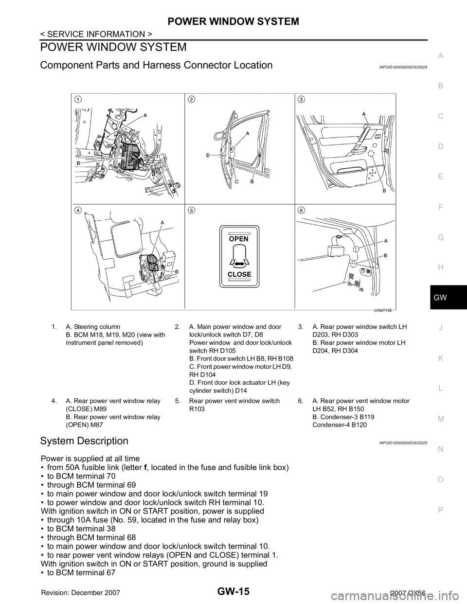
Component Parts and Harness Connector LocationINFOID:0000000003533024
System DescriptionINFOID:0000000003533025
Power is supplied at all time
• from 50A fusible link (letter f, located in the fuse and fusible link box)
• to BCM terminal 70
• through BCM terminal 69
• to main power window and door lock/unlock switch terminal 19
• to power window and door lock/unlock switch RH terminal 10.
With ignition switch in ON or START position, power is supplied
• through 10A fuse (No. 59, located in the fuse and relay box)
• to BCM terminal 38
• through BCM terminal 68
• to main power window and door lock/unlock switch terminal 10.
• to rear power vent window relays (OPEN and CLOSE) terminal 1.
With ignition switch in ON or START position, ground is supplied
• to BCM terminal 67
1. A. Steering column
B. BCM M18, M19, M20 (view with
instrument panel removed)2. A. Main power window and door
lock/unlock switch D7, D8
Power window and door lock/unlock
switch RH D105
B. Front door switch LH B8, RH B108
C. Front power window motor LH D9,
RH D104
D. Front door lock actuator LH (key
cylinder switch) D143. A. Rear power window switch LH
D203, RH D303
B. Rear power window motor LH
D204, RH D304
4. A. Rear power vent window relay
(CLOSE) M89
B. Rear power vent window relay
(OPEN) M875. Rear power vent window switch
R1036. A. Rear power vent window motor
LH B52, RH B150
B. Condenser-3 B119
Condenser-4 B120
LIIA2715E
Page 2036 of 3061
POWER WINDOW SYSTEM
GW-17
< SERVICE INFORMATION >
C
D
E
F
G
H
J
K
L
MA
B
GW
N
O
P
• through rear power window control unit LH or RH terminal 16
• through rear power window switch LH or RH terminal 1 and 7
• through rear power window switch LH or RH terminal 4
• through rear power window control unit LH or RH terminal 12
• to rear power window motor LH or RH terminal 1.
Then, the motor raises the window until the switch is released.
WINDOW DOWN
When the rear power window switch LH or RH is pressed in the down position, power is supplied
• to rear power window control unit LH or RH terminal 1
• through rear power window control unit LH or RH terminal 7
• through rear power window switch LH or RH terminal 2 and 3
• through rear power window switch LH or RH terminal 4
• through rear power window control unit LH or RH terminal 12
• to rear power window motor LH or RH terminal 1.
Ground is supplied
• to rear power window control unit LH or RH terminal 15
• through rear power window control unit LH or RH terminal 16
• through rear power window switch LH or RH terminal 1 and 7
• through rear power window switch LH or RH terminal 5
• through rear power window control unit LH or RH terminal 11
• to rear power window motor LH or RH terminal 2.
Then, the motor lowers the window until the switch is released.
MAIN POWER WINDOW AND DOOR LOCK/UNLOCK SWITCH OPERATION
Signal is sent
• through main power window and door lock/unlock switch terminal 14
• to rear power window control unit LH or RH terminal 1.
The operation of power window after receiving the signal is the same as operating the power window with rear
power window switch LH or RH.
VENT WINDOW CLOSE
When the rear power vent window switch is pressed in the close position, power is supplied
• to rear power vent window relay (CLOSE) terminal 5
• through rear power vent window relay (CLOSE) terminal 3
• to rear power vent window motors terminal 2.
Ground is supplied
• to rear power vent window relay (OPEN) terminal 4
• through rear power vent window relay (OPEN) terminal 3
• to rear power vent window motors terminal 1.
Then, the motors close the windows until the switch is released.
VENT WINDOW OPEN
When the main power window and door lock/unlock switch (rear LH) is pressed in the open position, power is
supplied
• to rear power vent window relay (OPEN) terminal 5
• through rear power vent window relay (OPEN) terminal 3
• to rear power vent window motors terminal 1.
Ground is supplied
• to rear power vent window relay (CLOSE) terminal 4
• through rear power vent window relay (CLOSE) terminal 3
• to rear power vent window motors terminal 2.
Then, the motors open the windows until the switch is released.
AUTO OPERATION
The power window AUTO feature enables the driver to open or close the window without holding the window
switch in the down or up position.
POWER WINDOW SERIAL LINK
Main power window and door lock/unlock switch, power window and door lock/unlock switch RH, rear power
window control units and BCM transmit and receive the signal by power window serial link.
The signal is transmitted from BCM to main power window and door lock/unlock switch and power window and
door lock/unlock switch RH
• Keyless power window down signal.
• Rear power window switch illumination.
Page 2037 of 3061
GW-18
< SERVICE INFORMATION >
POWER WINDOW SYSTEM
The signal is transmitted from main power window and door lock/unlock switch to power window and door
lock/unlock switch RH
• Front door window RH operation signal.
• Power window control by front door lock assembly LH (key cylinder switch) signal.
• Power window lock signal.
• Retained power operation signal.
• Rear power window operation.
POWER WINDOW LOCK
The power window lock is designed to lock operation of all windows except for front door window LH.
When in the lock position, the power window lock signal is transmitted to power window and door lock/unlock
switch RH by power window serial link. This prevents the power window motor from operating.
RETAINED POWER OPERATION
When the ignition switch is turned to the OFF position from ON or START position, power is supplied for 45
seconds
• to main power window and door lock/unlock switch terminal 10
• from BCM terminal 68.
When power and ground are supplied, the BCM continues to be energized, and the power window can be
operated.
The retained power operation is canceled when the front LH or front RH door is opened.
Retained power operation period can be changed by CONSULT-II. Refer to GW-31, "
CONSULT-II Function
(BCM)" .
ANTI-PINCH SYSTEM
Main power window and door lock/unlock switch, power window and door lock/unlock switch RH and rear
power window control unit LH and RH monitors the power window motor operation and the power window
position (full closed or other) for each power window by the signals from encoder and limit switch in power win-
dow motor.
When a window switch detects interruption during the following close operation,
• automatic close operation when ignition switch is in the ON position
• automatic close operation during retained power operation
Main power window and door lock/unlock switch, power window and door lock/unlock switch RH and rear
power window control unit LH and RH controls each power window motor for open and the power window will
be lowered about 150 mm (5.91 in).
POWER WINDOW CONTROL BY THE FRONT DOOR LOCK ASSEMBLY LH (KEY CYLINDER
SWITCH)
When ignition key switch is OFF, front power window LH and RH can be opened or closed by turning the front
door lock assembly LH (key cylinder switch) to the UNLOCK/LOCK position for more than 1 second.
• Front power windows can be opened as the front door lock assembly LH (key cylinder switch) is kept fully
turned to the UNLOCK position.
• Front power windows can be closed as the front door lock assembly LH (key cylinder switch) is kept fully
turned to the LOCK position.
• While performing open/close operation for the windows, power window is stopped when the front door lock
assembly LH (key cylinder switch) is placed in the NEUTRAL position.
• When the ignition switch is turned ON while the power window opening operation is performed, the power
window opening stops.
CAN Communication System DescriptionINFOID:0000000003533026
Refer to LAN-4.