ECU INFINITI QX56 2007 Factory Service Manual
[x] Cancel search | Manufacturer: INFINITI, Model Year: 2007, Model line: QX56, Model: INFINITI QX56 2007Pages: 3061, PDF Size: 64.56 MB
Page 1603 of 3061
EC-520
< SERVICE INFORMATION >
DTC P1572 ICC BRAKE SWITCH
DTC P1572 ICC BRAKE SWITCH
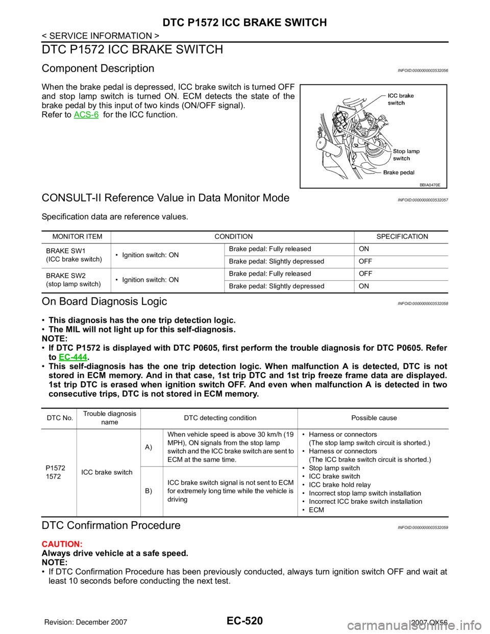
Component DescriptionINFOID:0000000003532056
When the brake pedal is depressed, ICC brake switch is turned OFF
and stop lamp switch is turned ON. ECM detects the state of the
brake pedal by this input of two kinds (ON/OFF signal).
Refer to ACS-6
for the ICC function.
CONSULT-II Reference Value in Data Monitor ModeINFOID:0000000003532057
Specification data are reference values.
On Board Diagnosis LogicINFOID:0000000003532058
•This diagnosis has the one trip detection logic.
•The MIL will not light up for this self-diagnosis.
NOTE:
•If DTC P1572 is displayed with DTC P0605, first perform the trouble diagnosis for DTC P0605. Refer
to EC-444
.
•This self-diagnosis has the one trip detection logic. When malfunction A is detected, DTC is not
stored in ECM memory. And in that case, 1st trip DTC and 1st trip freeze frame data are displayed.
1st trip DTC is erased when ignition switch OFF. And even when malfunction A is detected in two
consecutive trips, DTC is not stored in ECM memory.
DTC Confirmation ProcedureINFOID:0000000003532059
CAUTION:
Always drive vehicle at a safe speed.
NOTE:
• If DTC Confirmation Procedure has been previously conducted, always turn ignition switch OFF and wait at
least 10 seconds before conducting the next test.
BBIA0470E
MONITOR ITEM CONDITION SPECIFICATION
BRAKE SW1
(ICC brake switch)• Ignition switch: ONBrake pedal: Fully released ON
Brake pedal: Slightly depressed OFF
BRAKE SW2
(stop lamp switch)• Ignition switch: ONBrake pedal: Fully released OFF
Brake pedal: Slightly depressed ON
DTC No.Trouble diagnosis
nameDTC detecting condition Possible cause
P1572
1572ICC brake switchA)When vehicle speed is above 30 km/h (19
MPH), ON signals from the stop lamp
switch and the ICC brake switch are sent to
ECM at the same time.• Harness or connectors
(The stop lamp switch circuit is shorted.)
• Harness or connectors
(The ICC brake switch circuit is shorted.)
• Stop lamp switch
• ICC brake switch
• ICC brake hold relay
• Incorrect stop lamp switch installation
• Incorrect ICC brake switch installation
•ECM B)ICC brake switch signal is not sent to ECM
for extremely long time while the vehicle is
driving
Page 1604 of 3061
DTC P1572 ICC BRAKE SWITCH
EC-521
< SERVICE INFORMATION >
C
D
E
F
G
H
I
J
K
L
MA
EC
N
P O
• Procedure for malfunction B is not described here. It takes extremely long time to complete procedure for
malfunction B. By performing procedure for malfunction A, the incident that causes malfunction B can be
detected.
TESTING CONDITION:
Steps 4 and 5 may be conducted with the drive wheels lifted in the shop or by driving the vehicle. If a
road test is expected to be easier, it is unnecessary to lift the vehicle.
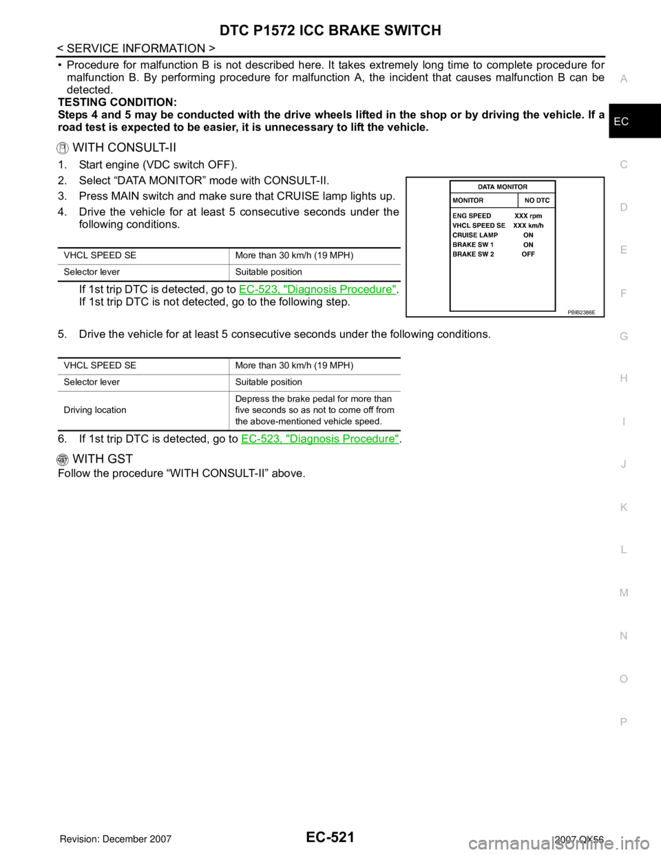
WITH CONSULT-II
1. Start engine (VDC switch OFF).
2. Select “DATA MONITOR” mode with CONSULT-II.
3. Press MAIN switch and make sure that CRUISE lamp lights up.
4. Drive the vehicle for at least 5 consecutive seconds under the
following conditions.
If 1st trip DTC is detected, go to EC-523, "
Diagnosis Procedure".
If 1st trip DTC is not detected, go to the following step.
5. Drive the vehicle for at least 5 consecutive seconds under the following conditions.
6. If 1st trip DTC is detected, go to EC-523, "
Diagnosis Procedure".
WITH GST
Follow the procedure “WITH CONSULT-II” above.
VHCL SPEED SE More than 30 km/h (19 MPH)
Selector lever Suitable position
PBIB2386E
VHCL SPEED SE More than 30 km/h (19 MPH)
Selector lever Suitable position
Driving locationDepress the brake pedal for more than
five seconds so as not to come off from
the above-mentioned vehicle speed.
Page 1611 of 3061
EC-528
< SERVICE INFORMATION >
DTC P1572 ASCD BRAKE SWITCH
DTC P1572 ASCD BRAKE SWITCH
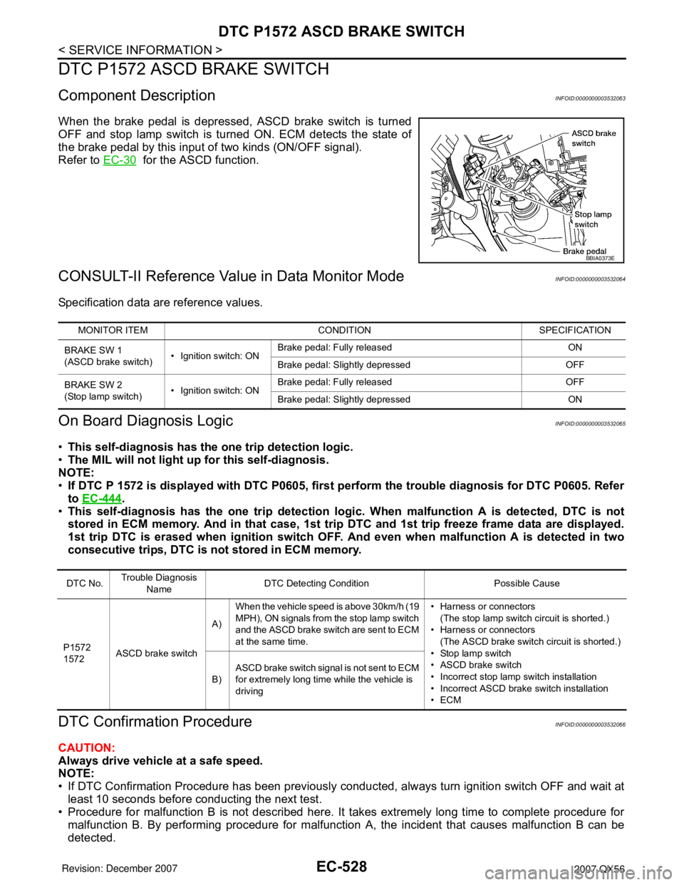
Component DescriptionINFOID:0000000003532063
When the brake pedal is depressed, ASCD brake switch is turned
OFF and stop lamp switch is turned ON. ECM detects the state of
the brake pedal by this input of two kinds (ON/OFF signal).
Refer to EC-30
for the ASCD function.
CONSULT-II Reference Value in Data Monitor ModeINFOID:0000000003532064
Specification data are reference values.
On Board Diagnosis LogicINFOID:0000000003532065
•This self-diagnosis has the one trip detection logic.
•The MIL will not light up for this self-diagnosis.
NOTE:
•If DTC P 1572 is displayed with DTC P0605, first perform the trouble diagnosis for DTC P0605. Refer
to EC-444
.
•This self-diagnosis has the one trip detection logic. When malfunction A is detected, DTC is not
stored in ECM memory. And in that case, 1st trip DTC and 1st trip freeze frame data are displayed.
1st trip DTC is erased when ignition switch OFF. And even when malfunction A is detected in two
consecutive trips, DTC is not stored in ECM memory.
DTC Confirmation ProcedureINFOID:0000000003532066
CAUTION:
Always drive vehicle at a safe speed.
NOTE:
• If DTC Confirmation Procedure has been previously conducted, always turn ignition switch OFF and wait at
least 10 seconds before conducting the next test.
• Procedure for malfunction B is not described here. It takes extremely long time to complete procedure for
malfunction B. By performing procedure for malfunction A, the incident that causes malfunction B can be
detected.
BBIA0373E
MONITOR ITEM CONDITION SPECIFICATION
BRAKE SW 1
(ASCD brake switch)• Ignition switch: ONBrake pedal: Fully released ON
Brake pedal: Slightly depressed OFF
BRAKE SW 2
(Stop lamp switch)• Ignition switch: ONBrake pedal: Fully released OFF
Brake pedal: Slightly depressed ON
DTC No.Trouble Diagnosis
NameDTC Detecting Condition Possible Cause
P1572
1572ASCD brake switchA)When the vehicle speed is above 30km/h (19
MPH), ON signals from the stop lamp switch
and the ASCD brake switch are sent to ECM
at the same time.• Harness or connectors
(The stop lamp switch circuit is shorted.)
• Harness or connectors
(The ASCD brake switch circuit is shorted.)
• Stop lamp switch
• ASCD brake switch
• Incorrect stop lamp switch installation
• Incorrect ASCD brake switch installation
•ECM B)ASCD brake switch signal is not sent to ECM
for extremely long time while the vehicle is
driving
Page 1612 of 3061
DTC P1572 ASCD BRAKE SWITCH
EC-529
< SERVICE INFORMATION >
C
D
E
F
G
H
I
J
K
L
MA
EC
N
P O
TESTING CONDITION:
Steps 4 and 5 may be conducted with the drive wheels lifted in the shop or by driving the vehicle. If a
road test is expected to be easier, it is unnecessary to lift the vehicle.
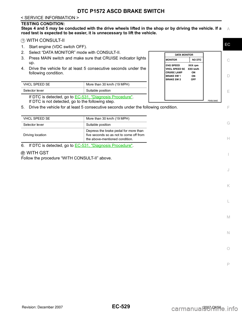
WITH CONSULT-II
1. Start engine (VDC switch OFF).
2. Select “DATA MONITOR” mode with CONSULT-II.
3. Press MAIN switch and make sure that CRUISE indicator lights
up.
4. Drive the vehicle for at least 5 consecutive seconds under the
following condition.
If DTC is detected, go to EC-531, "
Diagnosis Procedure".
If DTC is not detected, go to the following step.
5. Drive the vehicle for at least 5 consecutive seconds under the following condition.
6. If DTC is detected, go to EC-531, "
Diagnosis Procedure".
WITH GST
Follow the procedure “WITH CONSULT-II” above.
VHCL SPEED SE More than 30 km/h (19 MPH)
Selector lever Suitable position
VHCL SPEED SE More than 30 km/h (19 MPH)
Selector lever Suitable position
Driving locationDepress the brake pedal for more than
five seconds so as not to come off from
the above-mentioned condition.
PBIB2386E
Page 1734 of 3061
SQUEAK AND RATTLE TROUBLE DIAGNOSIS
EI-5
< SERVICE INFORMATION >
C
D
E
F
G
H
J
K
L
MA
B
EI
N
O
P
If the noise can be duplicated easily during the test drive, to help identify the source of the noise, try to dupli-
cate the noise with the vehicle stopped by doing one or all of the following:
1) Close a door.
2) Tap or push/pull around the area where the noise appears to be coming from.
3) Rev the engine.
4) Use a floor jack to recreate vehicle “twist”.
5) At idle, apply engine load (electrical load, half-clutch on M/T model, drive position on A/T model).
6) Raise the vehicle on a hoist and hit a tire with a rubber hammer.
• Drive the vehicle and attempt to duplicate the conditions the customer states exist when the noise occurs.
• If it is difficult to duplicate the noise, drive the vehicle slowly on an undulating or rough road to stress the
vehicle body.
CHECK RELATED SERVICE BULLETINS
After verifying the customer concern or symptom, check ASIST for Technical Service Bulletins (TSBs) related
to that concern or symptom.
If a TSB relates to the symptom, follow the procedure to repair the noise.
LOCATE THE NOISE AND IDENTIFY THE ROOT CAUSE
1. Narrow down the noise to a general area.To help pinpoint the source of the noise, use a listening tool
(Chassis Ear: J-39570, Engine Ear: J-39565 and mechanic's stethoscope).
2. Narrow down the noise to a more specific area and identify the cause of the noise by:
• removing the components in the area that you suspect the noise is coming from.
Do not use too much force when removing clips and fasteners, otherwise clips and fasteners can be broken
or lost during the repair, resulting in the creation of new noise.
• tapping or pushing/pulling the component that you suspect is causing the noise.
Do not tap or push/pull the component with excessive force, otherwise the noise will be eliminated only tem-
porarily.
• feeling for a vibration with your hand by touching the component(s) that you suspect is (are) causing the
noise.
• placing a piece of paper between components that you suspect are causing the noise.
• looking for loose components and contact marks.
Refer to EI-6, "
Generic Squeak and Rattle Troubleshooting".
REPAIR THE CAUSE
• If the cause is a loose component, tighten the component securely.
• If the cause is insufficient clearance between components:
- separate components by repositioning or loosening and retightening the component, if possible.
- insulate components with a suitable insulator such as urethane pads, foam blocks, felt cloth tape or urethane
tape. A NISSAN Squeak and Rattle Kit (J-43980) is available through your authorized NISSAN Parts Depart-
ment.
CAUTION:
Do not use excessive force as many components are constructed of plastic and may be damaged.
Always check with the Parts Department for the latest parts information.
The following materials are contained in the NISSAN Squeak and Rattle Kit (J-43980). Each item can be
ordered separately as needed.
URETHANE PADS [1.5 mm (0.059 in) thick]
Insulates connectors, harness, etc.
76268-9E005: 100×135 mm (3.94×5.31 in)/76884-71L01: 60×85 mm (2.36×3.35 in)/76884-71L02: 15×25
mm (0.59×0.98 in)
INSULATOR (Foam blocks)
Insulates components from contact. Can be used to fill space behind a panel.
73982-9E000: 45 mm (1.77 in) thick, 50×50 mm (1.97×1.97 in)/73982-50Y00: 10 mm (0.39 in) thick,
50×50 mm (1.97×1.97 in)
INSULATOR (Light foam block)
80845-71L00: 30 mm (1.18 in) thick, 30×50 mm (1.18×1.97 in)
FELT CLOTH TAPE
Used to insulate where movement does not occur. Ideal for instrument panel applications.
68370-4B000: 15×25 mm (0.59×0.98 in) pad/68239-13E00: 5 mm (0.20 in) wide tape roll. The following
materials not found in the kit can also be used to repair squeaks and rattles.
UHMW (TEFLON) TAPE
Insulates where slight movement is present. Ideal for instrument panel applications.
Page 1736 of 3061

SQUEAK AND RATTLE TROUBLE DIAGNOSIS
EI-7
< SERVICE INFORMATION >
C
D
E
F
G
H
J
K
L
MA
B
EI
N
O
P
Most of these incidents can be repaired by adjusting, securing or insulating the item(s) or component(s) caus-
ing the noise.
SUNROOF/HEADLINING
Noises in the sunroof/headlining area can often be traced to one of the following:
1. Sunroof lid, rail, linkage or seals making a rattle or light knocking noise
2. Sun visor shaft shaking in the holder
3. Front or rear windshield touching headliner and squeaking
Again, pressing on the components to stop the noise while duplicating the conditions can isolate most of these
incidents. Repairs usually consist of insulating with felt cloth tape.
OVERHEAD CONSOLE (FRONT AND REAR)
Overhead console noises are often caused by the console panel clips not being engaged correctly. Most of
these incidents are repaired by pushing up on the console at the clip locations until the clips engage.
In addition look for:
1. Loose harness or harness connectors.
2. Front console map/reading lamp lens loose.
3. Loose screws at console attachment points.
SEATS
When isolating seat noise it's important to note the position the seat is in and the load placed on the seat when
the noise is present. These conditions should be duplicated when verifying and isolating the cause of the
noise.
Cause of seat noise include:
1. Headrest rods and holder
2. A squeak between the seat pad cushion and frame
3. The rear seatback lock and bracket
These noises can be isolated by moving or pressing on the suspected components while duplicating the con-
ditions under which the noise occurs. Most of these incidents can be repaired by repositioning the component
or applying urethane tape to the contact area.
UNDERHOOD
Some interior noise may be caused by components under the hood or on the engine wall. The noise is then
transmitted into the passenger compartment.
Causes of transmitted underhood noise include:
1. Any component installed to the engine wall
2. Components that pass through the engine wall
3. Engine wall mounts and connectors
4. Loose radiator installation pins
5. Hood bumpers out of adjustment
6. Hood striker out of adjustment
These noises can be difficult to isolate since they cannot be reached from the interior of the vehicle. The best
method is to secure, move or insulate one component at a time and test drive the vehicle. Also, engine RPM
or load can be changed to isolate the noise. Repairs can usually be made by moving, adjusting, securing, or
insulating the component causing the noise.
Page 1749 of 3061
EI-20
< SERVICE INFORMATION >
OVER FENDER
OVER FENDER
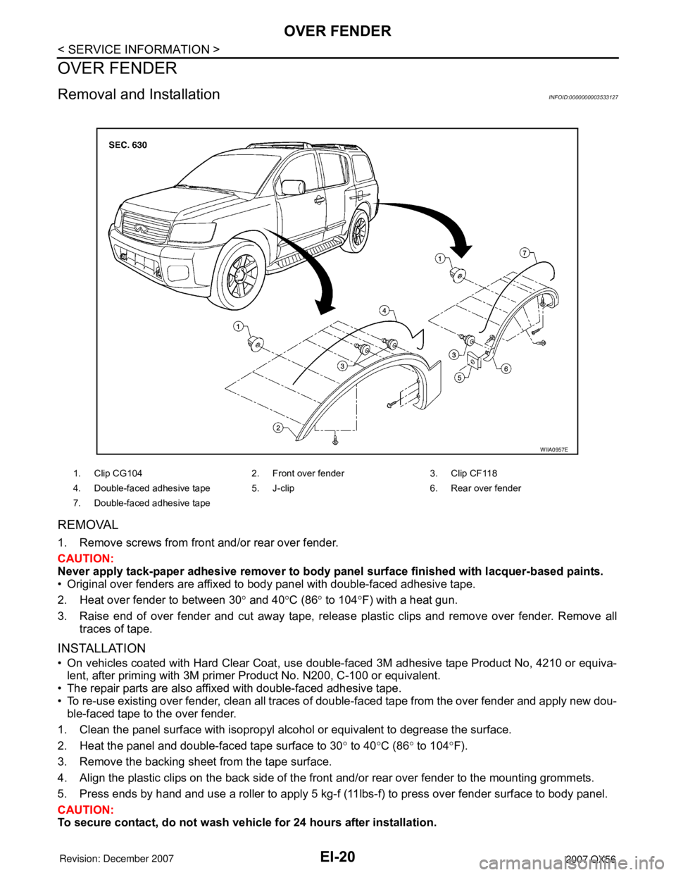
Removal and InstallationINFOID:0000000003533127
REMOVAL
1. Remove screws from front and/or rear over fender.
CAUTION:
Never apply tack-paper adhesive remover to body panel surface finished with lacquer-based paints.
• Original over fenders are affixed to body panel with double-faced adhesive tape.
2. Heat over fender to between 30° and 40°C (86° to 104°F) with a heat gun.
3. Raise end of over fender and cut away tape, release plastic clips and remove over fender. Remove all
traces of tape.
INSTALLATION
• On vehicles coated with Hard Clear Coat, use double-faced 3M adhesive tape Product No, 4210 or equiva-
lent, after priming with 3M primer Product No. N200, C-100 or equivalent.
• The repair parts are also affixed with double-faced adhesive tape.
• To re-use existing over fender, clean all traces of double-faced tape from the over fender and apply new dou-
ble-faced tape to the over fender.
1. Clean the panel surface with isopropyl alcohol or equivalent to degrease the surface.
2. Heat the panel and double-faced tape surface to 30° to 40°C (86° to 104°F).
3. Remove the backing sheet from the tape surface.
4. Align the plastic clips on the back side of the front and/or rear over fender to the mounting grommets.
5. Press ends by hand and use a roller to apply 5 kg-f (11lbs-f) to press over fender surface to body panel.
CAUTION:
To secure contact, do not wash vehicle for 24 hours after installation.
1. Clip CG104 2. Front over fender 3. Clip CF118
4. Double-faced adhesive tape 5. J-clip 6. Rear over fender
7. Double-faced adhesive tape
WIIA0957E
Page 1759 of 3061

EI-30
< SERVICE INFORMATION >
SIDE GUARD MOLDING
2. Heat the panel and double-faced adhesive tape surface to 30° to 40°C (86° to 104°F).
3. Remove the backing sheet from the double-faced adhesive tape surface.
• Align the plastic clips into the holes in the outer door.
• Continue aligning the plastic clips into their corresponding holes in the outer door during installation.
4. Press ends by hand and use a roller to apply 5 kg-f (11 lbs-f) to press double-faced adhesive tape surface
on side guard molding to door surface.
• Apply even pressure along double-faced adhesive tape surface on side guard molding to insure proper
wet out.
CAUTION:
To secure contact of double-faced adhesive tape, do not wash vehicle for 24 hours after installation.
Page 1784 of 3061
EM-14
< SERVICE INFORMATION >
DRIVE BELTS
INSTALLATION
Installation is in the reverse order of removal.
CAUTION:
Make sure belt is securely installed around all pulleys.
• Rotate the crankshaft pulley several turns clockwise to equalize belt tension between pulleys.
• Make sure belt tension is within the allowable working range, using the indicator notch on the drive belt auto
tensioner. Refer to EM-13, "
Checking Drive Belts".
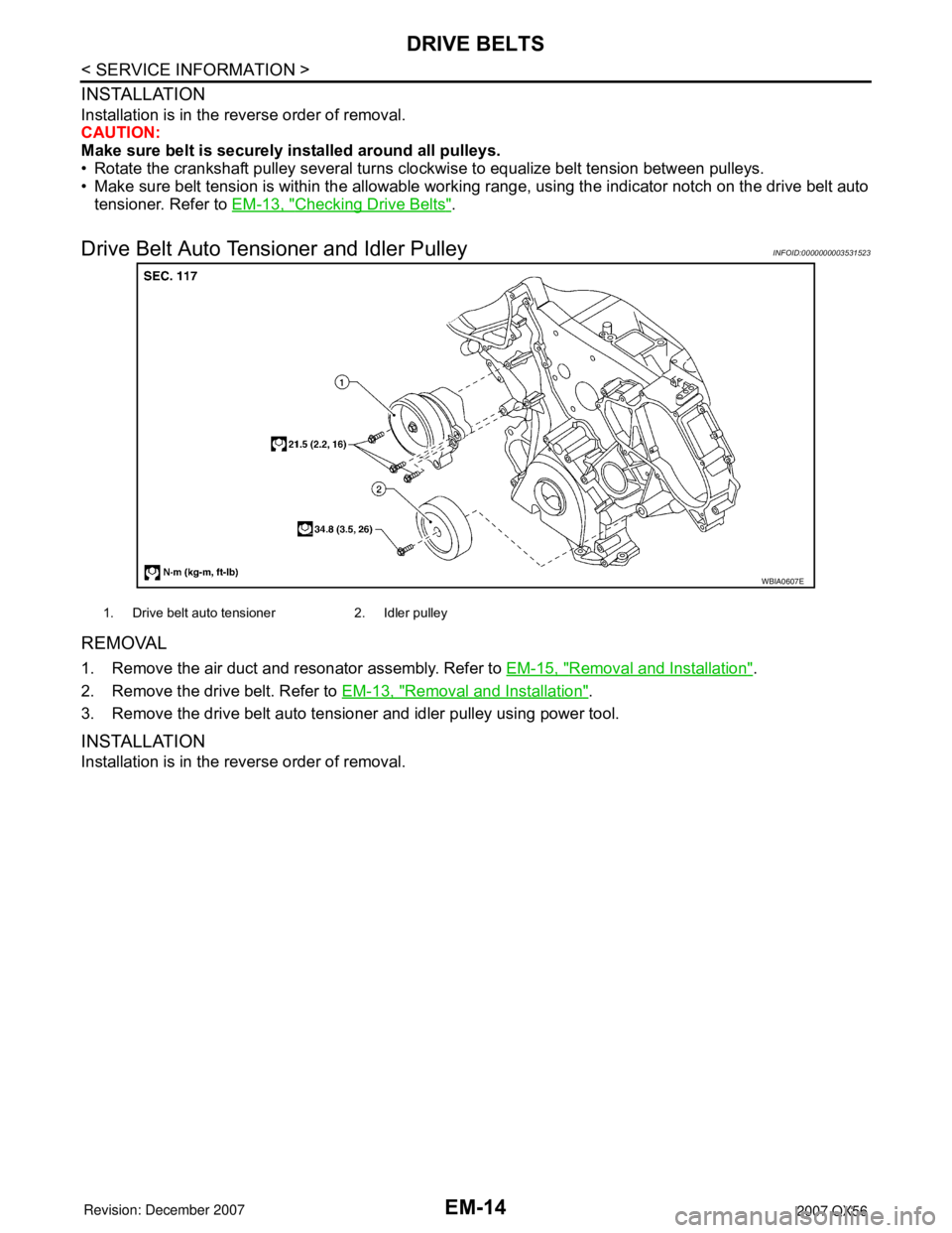
Drive Belt Auto Tensioner and Idler PulleyINFOID:0000000003531523
REMOVAL
1. Remove the air duct and resonator assembly. Refer to EM-15, "Removal and Installation".
2. Remove the drive belt. Refer to EM-13, "
Removal and Installation".
3. Remove the drive belt auto tensioner and idler pulley using power tool.
INSTALLATION
Installation is in the reverse order of removal.
WBIA0607E
1. Drive belt auto tensioner 2. Idler pulley
Page 1803 of 3061
FUEL INJECTOR AND FUEL TUBEEM-33
< SERVICE INFORMATION >
C
DE
F
G H
I
J
K L
M A
EM
NP
O
• Lubricate new O-ring with new engine oil.
• Do not clean O-ring with solvent.
• Make sure that O-ring and its mating
part are free of foreign material.
• When installing O-ring, be careful not to scratch it with tool or fingernails. Also be careful not to
twist or stretch O-ring.
• If O-ring was stretched while it was being att ached, do not insert it quickly into fuel tube.
• Insert O-ring straight into fuel tube. Do not angle or twist it.
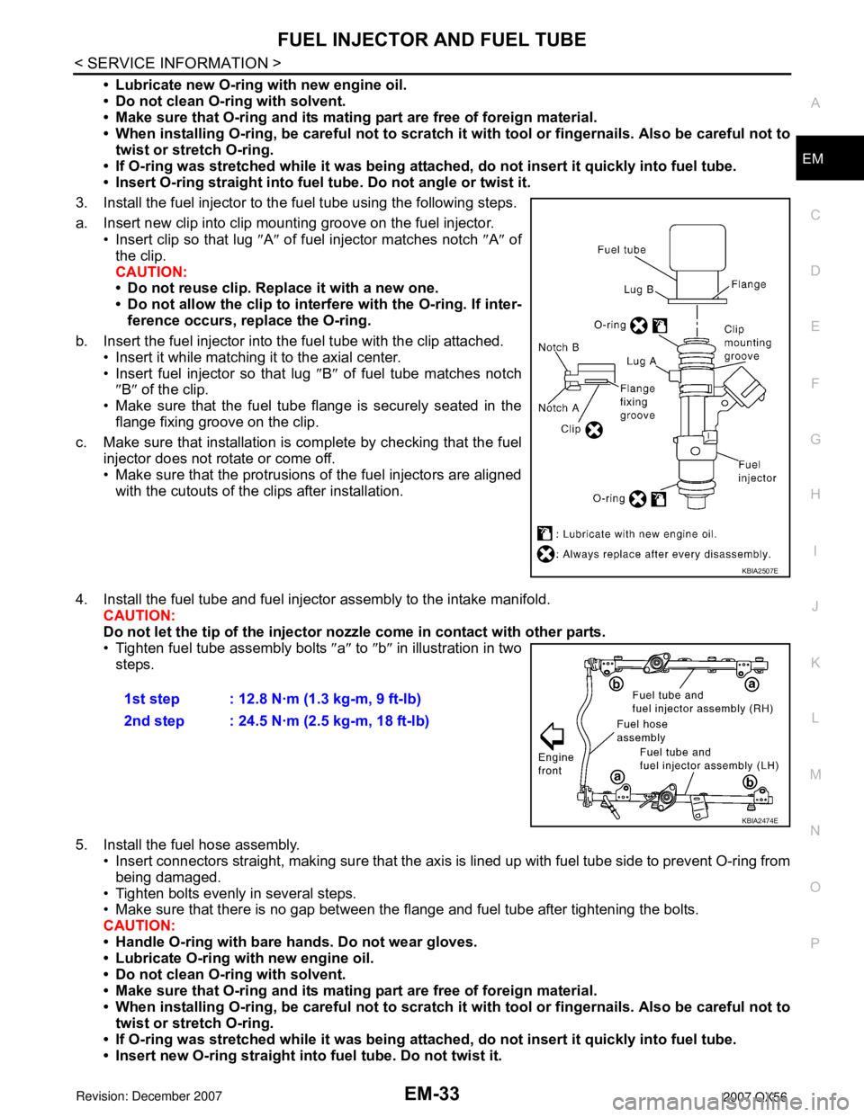
3. Install the fuel injector to the fuel tube using the following steps.
a. Insert new clip into clip mounting groove on the fuel injector. • Insert clip so that lug ″A ″ of fuel injector matches notch ″A ″ of
the clip.
CAUTION:
• Do not reuse clip. Replace it with a new one.
• Do not allow the clip to interf ere with the O-ring. If inter-
ference occurs, replace the O-ring.
b. Insert the fuel injector into the fuel tube with the clip attached. • Insert it while matching it to the axial center.
• Insert fuel injector so that lug ″B ″ of fuel tube matches notch
″ B ″ of the clip.
• Make sure that the fuel tube flange is securely seated in the flange fixing groove on the clip.
c. Make sure that installation is complete by checking that the fuel injector does not rotate or come off.
• Make sure that the protrusions of the fuel injectors are alignedwith the cutouts of the clips after installation.
4. Install the fuel tube and fuel injector assembly to the intake manifold. CAUTION:
Do not let the tip of the injector nozz le come in contact with other parts.
• Tighten fuel tube assembly bolts ″a ″ to ″b ″ in illustration in two
steps.
5. Install the fuel hose assembly. • Insert connectors straight, making su re that the axis is lined up with fuel tube side to prevent O-ring from
being damaged.
• Tighten bolts evenly in several steps.
• Make sure that there is no gap between the flange and fuel tube after tightening the bolts.
CAUTION:
• Handle O-ring with bare hands. Do not wear gloves.
• Lubricate O-ring with new engine oil.
• Do not clean O-ring with solvent.
• Make sure that O-ring and its mating part are free of foreign material.
• When installing O-ring, be careful not to scratch it with tool or fingernails. Also be careful not to
twist or stretch O-ring.
• If O-ring was stretched while it was being att ached, do not insert it quickly into fuel tube.
• Insert new O-ring straight into fuel tube. Do not twist it.
KBIA2507E
1st step : 12.8 N·m (1.3 kg-m, 9 ft-lb)
2nd step : 24.5 N·m (2.5 kg-m, 18 ft-lb)
KBIA2474E