air condition INFINITI QX56 2007 Factory Service Manual
[x] Cancel search | Manufacturer: INFINITI, Model Year: 2007, Model line: QX56, Model: INFINITI QX56 2007Pages: 3061, PDF Size: 64.56 MB
Page 973 of 3061
![INFINITI QX56 2007 Factory Service Manual TROUBLE DIAGNOSIS FOR SELF-DIAGNOSTIC ITEMS
BRC-45
< SERVICE INFORMATION >[VDC/TCS/ABS]
C
D
E
G
H
I
J
K
L
MA
B
BRC
N
O
P
OK or NG
OK >> GO TO 4.
NG >> Repair or replace harness or connector.
4.DELTA S INFINITI QX56 2007 Factory Service Manual TROUBLE DIAGNOSIS FOR SELF-DIAGNOSTIC ITEMS
BRC-45
< SERVICE INFORMATION >[VDC/TCS/ABS]
C
D
E
G
H
I
J
K
L
MA
B
BRC
N
O
P
OK or NG
OK >> GO TO 4.
NG >> Repair or replace harness or connector.
4.DELTA S](/img/42/57029/w960_57029-972.png)
TROUBLE DIAGNOSIS FOR SELF-DIAGNOSTIC ITEMS
BRC-45
< SERVICE INFORMATION >[VDC/TCS/ABS]
C
D
E
G
H
I
J
K
L
MA
B
BRC
N
O
P
OK or NG
OK >> GO TO 4.
NG >> Repair or replace harness or connector.
4.DELTA STROKE SENSOR INSPECTION
1. Reconnect the delta stroke sensor and ABS actuator and electric unit (control unit) connectors.
2. Use "DATA MONITOR" to check if the status of "DELTA S SEN" is normal.
OK or NG
OK >> Inspection End.
NG >> Replace delta stroke sensor.
Pressure Sensor System InspectionINFOID:0000000003532796
FRONT PRESSURE INSPECTION PROCEDURE
1.DISPLAY SELF DIAGNOSIS RESULTS
Check self-diagnosis result display item.
Is the above displayed in the self-diagnosis display items?
YES or NO
YES >> GO TO 2.
NO >> Inspection End.
2.CONNECTOR INSPECTION
1. Turn the ignition switch OFF.
2. Disconnect the front pressure sensor connector E31 and ABS actuator and electric unit (control unit) con-
nector E125 and inspect the terminals for deformation, disconnection, looseness, or damage.
OK or NG
OK >> GO TO 3.
NG >> Repair connector.
3.FRONT PRESSURE SENSOR CIRCUIT INSPECTION
1. Measure the continuity between the ABS actuator and electric unit (control unit) harness connector E125
and front pressure sensor harness connector E31.
2. Measure the continuity between the ABS actuator and electric unit (control unit) harness connector E125
and body ground.ConditionData monitor display (Approx.)
DELTA S SEN
When brake pedal is released 0.00 mm (+0.6/-0.4)
When brake pedal is depressed 1.05–1.80 mm
Self-diagnosis results
PRESS SEN CIRCUIT
ABS actuator and electric unit
(control unit) harness connector
E125Front pressure sensor har-
ness connector E31Continuity
18 3
Ye s 19 1
20 2
Page 974 of 3061
![INFINITI QX56 2007 Factory Service Manual BRC-46
< SERVICE INFORMATION >[VDC/TCS/ABS]
TROUBLE DIAGNOSIS FOR SELF-DIAGNOSTIC ITEMS
OK or NG
OK >> GO TO 4.
NG >> Repair or replace harness or connector.
4.FRONT PRESSURE SENSOR INSPECTION
1. Reco INFINITI QX56 2007 Factory Service Manual BRC-46
< SERVICE INFORMATION >[VDC/TCS/ABS]
TROUBLE DIAGNOSIS FOR SELF-DIAGNOSTIC ITEMS
OK or NG
OK >> GO TO 4.
NG >> Repair or replace harness or connector.
4.FRONT PRESSURE SENSOR INSPECTION
1. Reco](/img/42/57029/w960_57029-973.png)
BRC-46
< SERVICE INFORMATION >[VDC/TCS/ABS]
TROUBLE DIAGNOSIS FOR SELF-DIAGNOSTIC ITEMS
OK or NG
OK >> GO TO 4.
NG >> Repair or replace harness or connector.
4.FRONT PRESSURE SENSOR INSPECTION
1. Reconnect the front pressure sensor and ABS actuator and electric unit (control unit) connectors.
2. Use "DATA MONITOR" to check if the status of "PRESS SENSOR" is normal.
OK or NG
OK >> Inspection End.
NG >> Replace pressure sensor.
REAR PRESSURE INSPECTION PROCEDURE
1.DISPLAY SELF DIAGNOSIS RESULTS
Check self-diagnosis result display item.
Is the above displayed in the self-diagnosis display items?
YES or NO
YES >> GO TO 2.
NO >> Inspection End.
2.CONNECTOR INSPECTION
1. Turn the ignition switch OFF.
2. Disconnect the rear pressure sensor connector E32 and ABS actuator and electric unit (control unit) con-
nector E125 and inspect the terminals for deformation, disconnection, looseness, or damage.
OK or NG
OK >> GO TO 3.
NG >> Repair connector.
3.REAR PRESSURE SENSOR CIRCUIT INSPECTION
1. Measure the continuity between the ABS actuator and electric unit (control unit) connector E125 and rear
pressure sensor connector E32.ABS actuator and electric unit
(control unit) harness connector
E125Body ground Continuity
18
—No 19
20
ConditionData monitor display (Approx.)
PRESS SENSOR
When brake pedal is depressed Positive value
When brake pedal is released 0 bar
Self-diagnosis results
PRESS SEN CIRCUIT
ABS actuator and electric unit (con-
trol unit) connector E125Rear pressure sensor con-
nector E32Continuity
21 1
Ye s 22 3
23 2
Page 975 of 3061
![INFINITI QX56 2007 Factory Service Manual TROUBLE DIAGNOSIS FOR SELF-DIAGNOSTIC ITEMS
BRC-47
< SERVICE INFORMATION >[VDC/TCS/ABS]
C
D
E
G
H
I
J
K
L
MA
B
BRC
N
O
P
2. Measure the continuity between the ABS actuator and electric unit (control u INFINITI QX56 2007 Factory Service Manual TROUBLE DIAGNOSIS FOR SELF-DIAGNOSTIC ITEMS
BRC-47
< SERVICE INFORMATION >[VDC/TCS/ABS]
C
D
E
G
H
I
J
K
L
MA
B
BRC
N
O
P
2. Measure the continuity between the ABS actuator and electric unit (control u](/img/42/57029/w960_57029-974.png)
TROUBLE DIAGNOSIS FOR SELF-DIAGNOSTIC ITEMS
BRC-47
< SERVICE INFORMATION >[VDC/TCS/ABS]
C
D
E
G
H
I
J
K
L
MA
B
BRC
N
O
P
2. Measure the continuity between the ABS actuator and electric unit (control unit) connector E125 and body
ground.
OK or NG
OK >> GO TO 4.
NG >> Repair or replace harness or connector.
4.REAR PRESSURE SENSOR INSPECTION
1. Reconnect the rear pressure sensor and ABS actuator and electric unit (control unit) connectors.
2. Use "DATA MONITOR" to check if the status of "PRESS SEN 2" is normal.
OK or NG
OK >> Inspection End.
NG >> Replace rear pressure sensor.
Steering Angle Sensor Safe Mode InspectionINFOID:0000000003532797
INSPECTION PROCEDURE
1.INDICATOR LAMP CHECK
Check that VDC OFF indicator lamp is on.
OK or NG
OK >> GO TO 2.
NG >> GO TO 3.
2.ADJUSTMENT OF STEERING ANGLE SENSOR NEUTRAL POSITION
Adjust steering angle sensor neutral position. Refer to BRC-54, "
Adjustment of Steering Angle Sensor Neutral
Position".
OK or NG
OK >> GO TO 3.
NG >> Check steering angle sensor. Refer to BRC-36, "
Steering Angle Sensor System".
3.INDICATOR LAMP CHECK
Check that VDC OFF indicator lamp is off.
OK or NG
OK >> GO TO 4.
NG >> Perform basic inspection. Refer to BRC-22, "
Basic Inspection".
4.CHECK SELF-DIAGNOSTIC RESULTS
Perform ABS actuator and electric unit (control unit) self-diagnosis.
NOTE:ABS actuator and electric unit (con-
trol unit) connector E125Body ground Continuity
21
—No 22
23
ConditionData monitor display (Approx.)
PRESS SEN 2
When brake pedal is depressed Positive value
When brake pedal is released 0 bar
Self-diagnosis results
ST ANGL SEN SAFE
Page 979 of 3061
![INFINITI QX56 2007 Factory Service Manual TROUBLE DIAGNOSES FOR SYMPTOMS
BRC-51
< SERVICE INFORMATION >[VDC/TCS/ABS]
C
D
E
G
H
I
J
K
L
MA
B
BRC
N
O
P
3.CHECK CONNECTOR AND BRAKING PERFORMANCE
1. Disable ABS by disconnecting ABS actuator and e INFINITI QX56 2007 Factory Service Manual TROUBLE DIAGNOSES FOR SYMPTOMS
BRC-51
< SERVICE INFORMATION >[VDC/TCS/ABS]
C
D
E
G
H
I
J
K
L
MA
B
BRC
N
O
P
3.CHECK CONNECTOR AND BRAKING PERFORMANCE
1. Disable ABS by disconnecting ABS actuator and e](/img/42/57029/w960_57029-978.png)
TROUBLE DIAGNOSES FOR SYMPTOMS
BRC-51
< SERVICE INFORMATION >[VDC/TCS/ABS]
C
D
E
G
H
I
J
K
L
MA
B
BRC
N
O
P
3.CHECK CONNECTOR AND BRAKING PERFORMANCE
1. Disable ABS by disconnecting ABS actuator and electric unit (control unit) connector.
2. Drive vehicle and check brake operation.
NOTE:
• Stopping distance may be longer than vehicles without ABS when road condition is slippery.
• Driving the vehicle with the ABS actuator and electric unit (control unit) disconnected may induce DTCs
in electrical control units using CAN communication. After the inspection, clear all DTCs. Refer to LAN-
7.
OK or NG
OK >> GO TO 4.
NG >> Perform Basic Inspection. Refer to BRC-22, "
Basic Inspection".
4.CHECK WHEEL SENSORS
Check the following.
• Wheel sensor mounting for looseness
• Wheel sensors for physical damage
• Wheel sensor connectors for terminal damage or loose connections
OK or NG
OK >> Check ABS actuator and electric unit (control unit) connector terminals for deformation, discon-
nection, looseness or damage. Reconnect ABS actuator and electric unit (control unit) harness
connector. Then retest.
NG >> Repair or replace as necessary.
Long Stopping DistanceINFOID:0000000003532804
INSPECTION PROCEDURE
1.CHECK BASE BRAKING SYSTEM PERFORMANCE
1. Disable ABS by disconnecting ABS actuator and electric unit (control unit) connector.
2. Drive vehicle and check brake operation.
NOTE:
• Stopping distance may be longer than vehicles without ABS when road condition is slippery.
• Driving the vehicle with the ABS actuator and electric unit (control unit) disconnected may induce DTCs
in electrical control units using CAN communication. After the inspection, clear all DTCs. Refer to LAN-
7.
OK or NG
OK >> Go to BRC-50, "ABS Works Frequently".
NG >> Perform Basic Inspection. Refer to BRC-22, "
Basic Inspection".
ABS Does Not WorkINFOID:0000000003532805
CAUTION:
The ABS does not operate when the vehicle speed is 10 km/h (6 MPH) or less.
INSPECTION PROCEDURE
1.CHECK WARNING LAMP ACTIVATION
Turn ignition switch ON and check for warning lamp activation.
• Warning lamp should activate for approximately 2 seconds after turning the ignition switch ON.
OK or NG
OK >> Carry out self-diagnosis. Refer to BRC-26, "CONSULT-II Function (ABS)".
NG >> Go to BRC-22, "
Basic Inspection".
Pedal Vibration or ABS Operation NoiseINFOID:0000000003532806
NOTE:
During ABS activation, pedal vibration may be felt and a noise may be heard. This is normal and does not indi-
cate a malfunction.
INSPECTION PROCEDURE
Page 1004 of 3061
RADIATOR
CO-15
< SERVICE INFORMATION >
C
D
E
F
G
H
I
J
K
L
MA
CO
N
P O
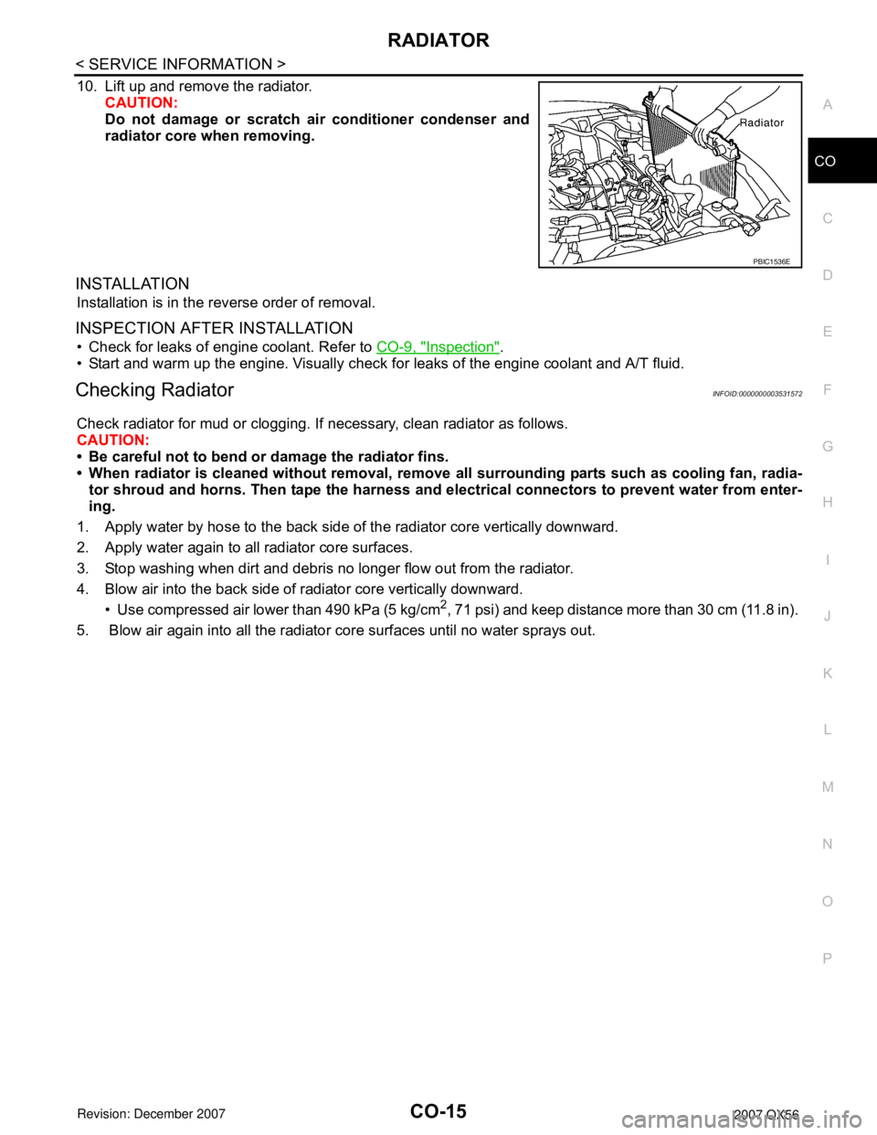
10. Lift up and remove the radiator.
CAUTION:
Do not damage or scratch air conditioner condenser and
radiator core when removing.
INSTALLATION
Installation is in the reverse order of removal.
INSPECTION AFTER INSTALLATION
• Check for leaks of engine coolant. Refer to CO-9, "Inspection".
• Start and warm up the engine. Visually check for leaks of the engine coolant and A/T fluid.
Checking RadiatorINFOID:0000000003531572
Check radiator for mud or clogging. If necessary, clean radiator as follows.
CAUTION:
• Be careful not to bend or damage the radiator fins.
• When radiator is cleaned without removal, remove all surrounding parts such as cooling fan, radia-
tor shroud and horns. Then tape the harness and electrical connectors to prevent water from enter-
ing.
1. Apply water by hose to the back side of the radiator core vertically downward.
2. Apply water again to all radiator core surfaces.
3. Stop washing when dirt and debris no longer flow out from the radiator.
4. Blow air into the back side of radiator core vertically downward.
• Use compressed air lower than 490 kPa (5 kg/cm
2, 71 psi) and keep distance more than 30 cm (11.8 in).
5. Blow air again into all the radiator core surfaces until no water sprays out.
PBIC1536E
Page 1005 of 3061
CO-16
< SERVICE INFORMATION >
ENGINE COOLING FAN
ENGINE COOLING FAN
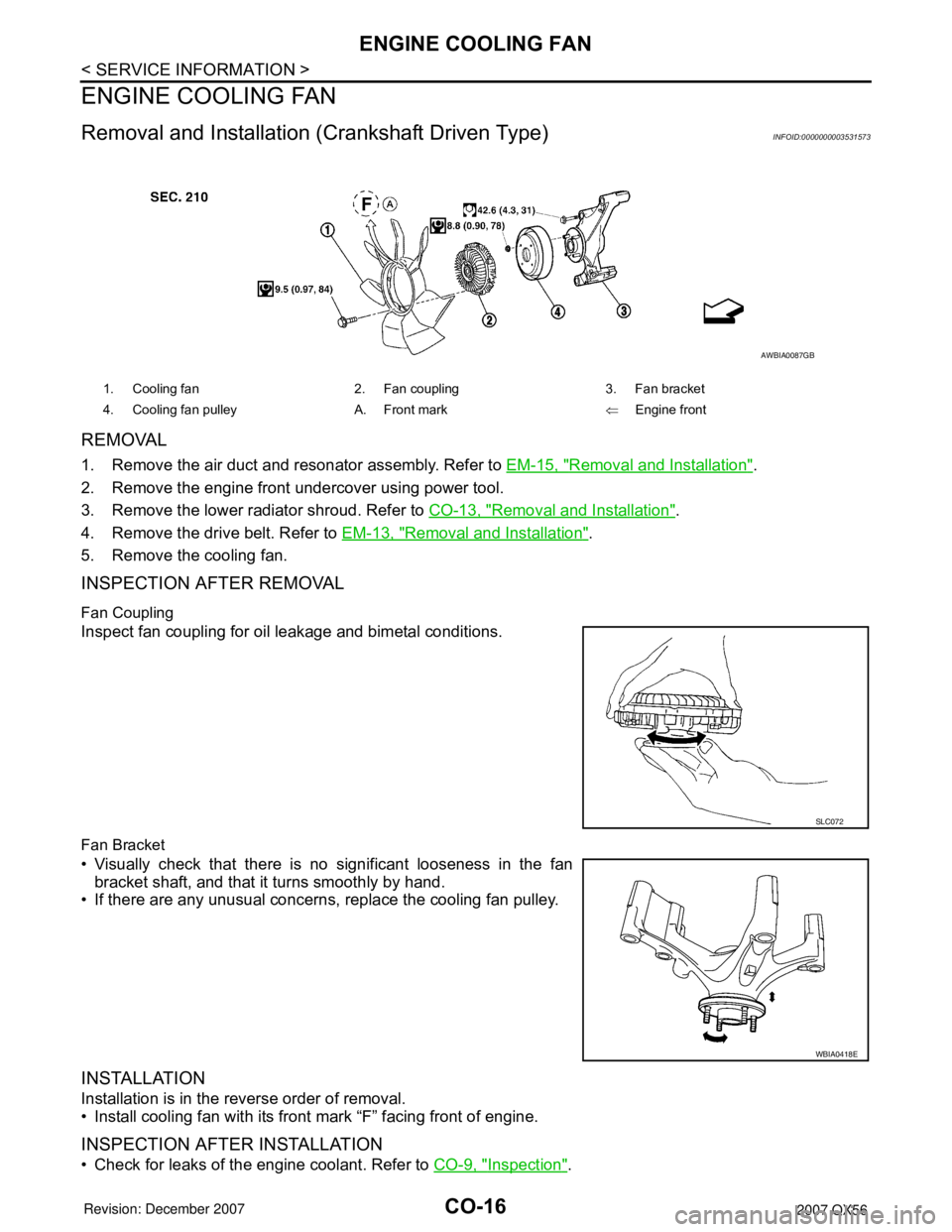
Removal and Installation (Crankshaft Driven Type)INFOID:0000000003531573
REMOVAL
1. Remove the air duct and resonator assembly. Refer to EM-15, "Removal and Installation".
2. Remove the engine front undercover using power tool.
3. Remove the lower radiator shroud. Refer to CO-13, "
Removal and Installation".
4. Remove the drive belt. Refer to EM-13, "
Removal and Installation".
5. Remove the cooling fan.
INSPECTION AFTER REMOVAL
Fan Coupling
Inspect fan coupling for oil leakage and bimetal conditions.
Fan Bracket
• Visually check that there is no significant looseness in the fan
bracket shaft, and that it turns smoothly by hand.
• If there are any unusual concerns, replace the cooling fan pulley.
INSTALLATION
Installation is in the reverse order of removal.
• Install cooling fan with its front mark “F” facing front of engine.
INSPECTION AFTER INSTALLATION
• Check for leaks of the engine coolant. Refer to CO-9, "Inspection".
1. Cooling fan 2. Fan coupling 3. Fan bracket
4. Cooling fan pulley A. Front mark⇐Engine front
AWBIA0087GB
SLC072
WBIA0418E
Page 1031 of 3061
DI-20
< SERVICE INFORMATION >
COMBINATION METERS
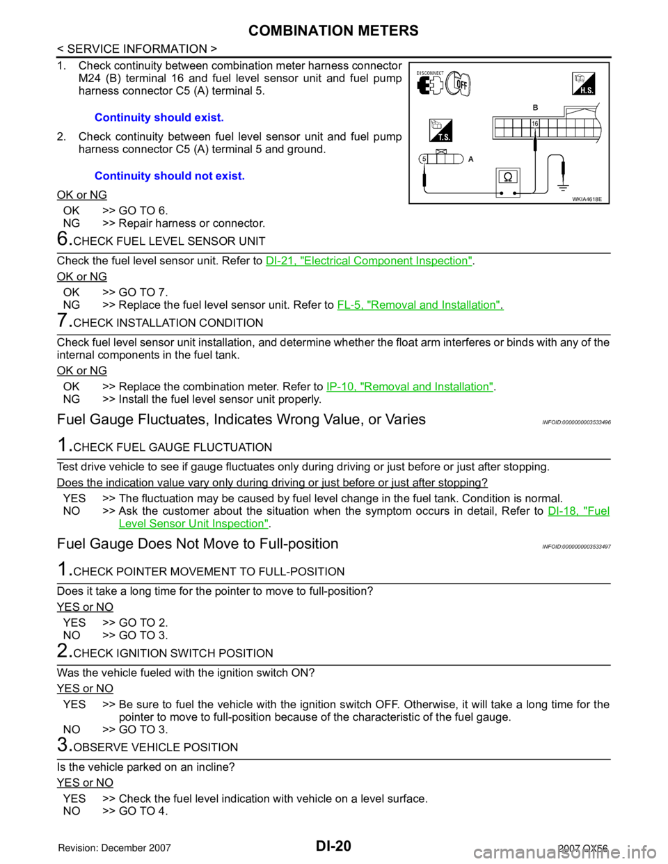
1. Check continuity between combination meter harness connectorM24 (B) terminal 16 and fuel level sensor unit and fuel pump
harness connector C5 (A) terminal 5.
2. Check continuity between fuel level sensor unit and fuel pump harness connector C5 (A) terminal 5 and ground.
OK or NG
OK >> GO TO 6.
NG >> Repair harness or connector.
6.CHECK FUEL LEVEL SENSOR UNIT
Check the fuel level sensor unit. Refer to DI-21, "
Electrical Component Inspection".
OK or NG
OK >> GO TO 7.
NG >> Replace the fuel level sensor unit. Refer to FL-5, "
Removal and Installation".
7.CHECK INSTALLATION CONDITION
Check fuel level sensor unit installation, and determine whet her the float arm interferes or binds with any of the
internal components in the fuel tank.
OK or NG
OK >> Replace the combination meter. Refer to IP-10, "Removal and Installation".
NG >> Install the fuel level sensor unit properly.
Fuel Gauge Fluctuat es, Indicates Wrong Value, or VariesINFOID:0000000003533496
1.CHECK FUEL GAUGE FLUCTUATION
Test drive vehicle to see if gauge fluctuates only during driving or just before or just after stopping.
Does the indication value vary only during driving or just before or just after stopping?
YES >> The fluctuation may be caused by fuel leve l change in the fuel tank. Condition is normal.
NO >> Ask the customer about the situation when the symptom occurs in detail, Refer to DI-18, "
Fuel
Level Sensor Unit Inspection".
Fuel Gauge Does Not Move to Full-positionINFOID:0000000003533497
1.CHECK POINTER MOVEME NT TO FULL-POSITION
Does it take a long time for the pointer to move to full-position?
YES or NO
YES >> GO TO 2.
NO >> GO TO 3.
2.CHECK IGNITION SWITCH POSITION
Was the vehicle fueled with the ignition switch ON?
YES or NO
YES >> Be sure to fuel the vehicle with the ignition s witch OFF. Otherwise, it will take a long time for the
pointer to move to full-position because of the characteristic of the fuel gauge.
NO >> GO TO 3.
3.OBSERVE VEHICLE POSITION
Is the vehicle parked on an incline?
YES or NO
YES >> Check the fuel level indication with vehicle on a level surface.
NO >> GO TO 4. Continuity should exist.
Continuity should not exist.
WKIA4618E
Page 1051 of 3061
DI-40
< SERVICE INFORMATION >
WARNING CHIME
How to Proceed with Trouble Diagnosis
INFOID:0000000003533516
1. Confirm the symptom or customer complaint.
2. Understand operation description and function description. Refer to DI-36, "
System Description".
3. Perform the preliminary check. Refer to DI-40, "
Preliminary Check".
4. Check symptom and repair or replace the cause of malfunction.
5. Does the warning chime operate properly? If so, go to 6. If not, go to 3.
6. Inspection End.
Preliminary CheckINFOID:0000000003533517
INSPECTION FOR POWER SUPPLY AND GROUND CIRCUIT
Refer to BCS-15, "BCM Power Supply and Ground Circuit Inspection".
CONSULT-II Function (BCM)INFOID:0000000003533518
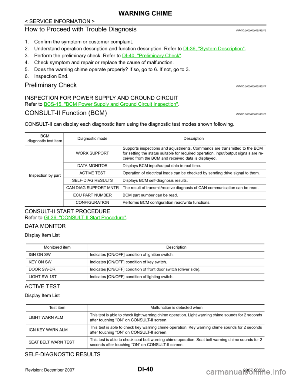
CONSULT-II can display each diagnostic item using the diagnostic test modes shown following.
CONSULT-II START PROCEDURE
Refer to GI-36, "CONSULT-II Start Procedure".
DATA MONITOR
Display Item List
ACTIVE TEST
Display Item List
SELF-DIAGNOSTIC RESULTS
BCM
diagnostic test itemDiagnostic mode Description
Inspection by partWORK SUPPORTSupports inspections and adjustments. Commands are transmitted to the BCM
for setting the status suitable for required operation, input/output signals are re-
ceived from the BCM and received data is displayed.
DATA MONITOR Displays BCM input/output data in real time.
ACTIVE TEST Operation of electrical loads can be checked by sending drive signal to them.
SELF-DIAG RESULTS Displays BCM self-diagnosis results.
CAN DIAG SUPPORT MNTR The result of transmit/receive diagnosis of CAN communication can be read.
ECU PART NUMBER BCM part number can be read.
CONFIGURATION Performs BCM configuration read/write functions.
Monitored item Description
IGN ON SW Indicates [ON/OFF] condition of ignition switch.
KEY ON SW Indicates [ON/OFF] condition of key switch.
DOOR SW-DR Indicates [ON/OFF] condition of front door switch (driver side).
LIGHT SW 1ST Indicates [ON/OFF] condition of lighting switch.
Test item Malfunction is detected when
LIGHT WARN ALMThis test is able to check light warning chime operation. Light warning chime sounds for 2 seconds
after touching “ON” on CONSULT-II screen.
IGN KEY WARN ALMThis test is able to check key warning chime operation. Key warning chime sounds for 2 seconds
after touching “ON” on CONSULT-II screen.
SEAT BELT WARN TESTThis test is able to check seat belt warning chime operation. Seat belt warning chime sounds for 2
seconds after touching “ON” on CONSULT-II screen.
Page 1054 of 3061
WARNING CHIME
DI-43
< SERVICE INFORMATION >
C
D
E
F
G
H
I
J
L
MA
B
DI
N
O
P
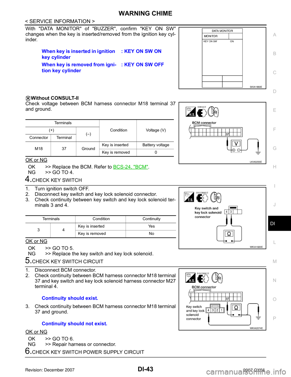
With "DATA MONITOR" of "BUZZER", confirm "KEY ON SW"
changes when the key is inserted/removed from the ignition key cyl-
inder.
Without CONSULT-II
Check voltage between BCM harness connector M18 terminal 37
and ground.
OK or NG
OK >> Replace the BCM. Refer to BCS-24, "BCM".
NG >> GO TO 4.
4.CHECK KEY SWITCH
1. Turn ignition switch OFF.
2. Disconnect key switch and key lock solenoid connector.
3. Check continuity between key switch and key lock solenoid ter-
minals 3 and 4.
OK or NG
OK >> GO TO 5.
NG >> Replace the key switch and key lock solenoid.
5.CHECK KEY SWITCH CIRCUIT
1. Disconnect BCM connector.
2. Check continuity between BCM harness connector M18 terminal
37 and key switch and key lock solenoid harness connector M27
terminal 4.
3. Check continuity between BCM harness connector M18 terminal
37 and ground.
OK or NG
OK >> GO TO 6.
NG >> Repair harness or connector.
6.CHECK KEY SWITCH POWER SUPPLY CIRCUITWhen key is inserted in ignition
key cylinder: KEY ON SW ON
When key is removed from igni-
tion key cylinder: KEY ON SW OFF
SKIA1960E
Te r m i n a l s
Condition Voltage (V) (+)
(–)
Connector Terminal
M18 37 GroundKey is insertedBattery voltage
Key is removed 0
LKIA0255E
Terminals Condition Continuity
34Key is inserted Yes
Key is removed No
WKIA1820E
Continuity should exist.
Continuity should not exist.
WKIA2074E
Page 1056 of 3061
WARNING CHIME
DI-45
< SERVICE INFORMATION >
C
D
E
F
G
H
I
J
L
MA
B
DI
N
O
P
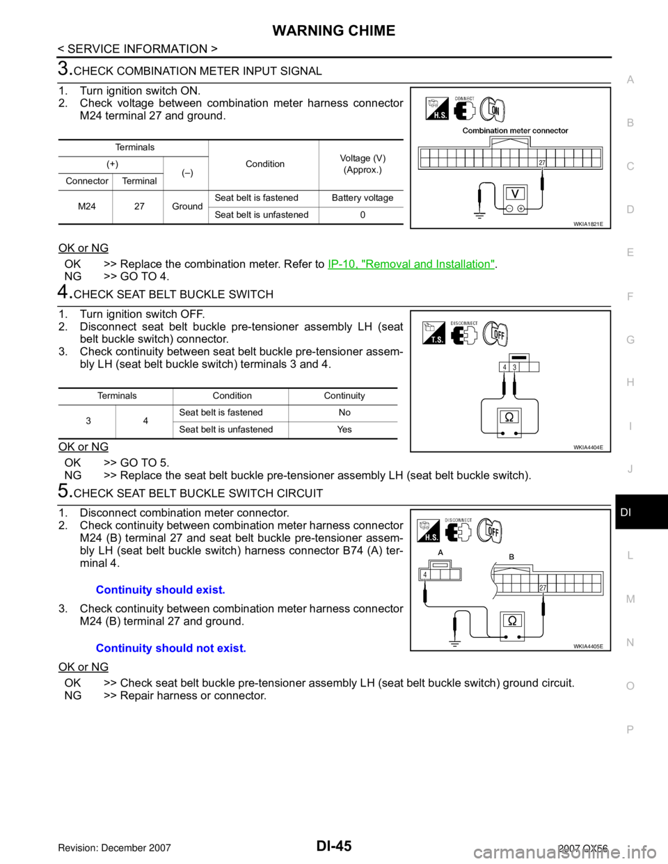
3.CHECK COMBINATION METER INPUT SIGNAL
1. Turn ignition switch ON.
2. Check voltage between combination meter harness connector
M24 terminal 27 and ground.
OK or NG
OK >> Replace the combination meter. Refer to IP-10, "Removal and Installation".
NG >> GO TO 4.
4.CHECK SEAT BELT BUCKLE SWITCH
1. Turn ignition switch OFF.
2. Disconnect seat belt buckle pre-tensioner assembly LH (seat
belt buckle switch) connector.
3. Check continuity between seat belt buckle pre-tensioner assem-
bly LH (seat belt buckle switch) terminals 3 and 4.
OK or NG
OK >> GO TO 5.
NG >> Replace the seat belt buckle pre-tensioner assembly LH (seat belt buckle switch).
5.CHECK SEAT BELT BUCKLE SWITCH CIRCUIT
1. Disconnect combination meter connector.
2. Check continuity between combination meter harness connector
M24 (B) terminal 27 and seat belt buckle pre-tensioner assem-
bly LH (seat belt buckle switch) harness connector B74 (A) ter-
minal 4.
3. Check continuity between combination meter harness connector
M24 (B) terminal 27 and ground.
OK or NG
OK >> Check seat belt buckle pre-tensioner assembly LH (seat belt buckle switch) ground circuit.
NG >> Repair harness or connector.
Te r m i n a l s
ConditionVoltage (V)
(Approx.) (+)
(–)
Connector Terminal
M24 27 GroundSeat belt is fastened Battery voltage
Seat belt is unfastened 0
WKIA1821E
Terminals Condition Continuity
34Seat belt is fastened No
Seat belt is unfastened Yes
WKIA4404E
Continuity should exist.
Continuity should not exist.
WKIA4405E