wheel bolts INFINITI QX56 2007 Factory Owner's Manual
[x] Cancel search | Manufacturer: INFINITI, Model Year: 2007, Model line: QX56, Model: INFINITI QX56 2007Pages: 3061, PDF Size: 64.56 MB
Page 2525 of 3061

REAR DRIVE SHAFT
RAX-7
< SERVICE INFORMATION >
C
E
F
G
H
I
J
K
L
MA
B
RAX
N
O
P
REAR DRIVE SHAFT
ComponentINFOID:0000000003532626
Rear Drive Shaft
Removal and InstallationINFOID:0000000003532627
REMOVAL
1. Remove the wheel and tire using power tool.
2. Remove the stabilizer bar clamp. Refer to RSU-21, "
Component".
3. Remove the cotter pin and discard, then remove the drive shaft
nut from the drive shaft.
• Do not reuse the cotter pin, discard after removal and use a
new cotter pin for installation.
4. Remove the six bolts from the inside flange of the drive shaft using power tool.
• Do not reuse the drive shaft inside flange bolts, discard after removal and use new bolts for installation.
WDIA0263E
1. Rear final drive assembly 2. Rear drive shaft 3. Rear brake and hub assembly
4. Cotter pin
LDIA0050E
Page 2526 of 3061
RAX-8
< SERVICE INFORMATION >
REAR DRIVE SHAFT
5. Separate the drive shaft from the wheel hub and bearing assembly by lightly tapping the end with a suit-
able hammer and wood block. If it is difficult to separate, use a suitable puller.
6. Remove the drive shaft.
CAUTION:
When removing the drive shaft, do not bend at an excessive angle to the drive shaft joint. Do not
excessively extend the slide joint.
INSPECTION AFTER REMOVAL
• Move the joint up and down, left and right, and in the axial direc-
tion. Check for any rough movement or significant looseness.
• Check the boot for cracks or other damage, and for any grease
leakage.
• If necessary, disassemble the drive shaft, and repair as necessary.
INSTALLATION
Installation is in the reverse order of removal.
• Do not reuse the drive shaft inside flange bolts, discard after removal and use new bolts for installation.
• Do not reuse the cotter pin, discard after removal and use a new cotter pin for installation.
Disassembly and AssemblyINFOID:0000000003532628
DISASSEMBLY
Final Drive Side
1. Mount the drive shaft in a vise.
CAUTION:
RAA0030D
Drive shaft lock nut : Refer to RAX-7, "Component".
Drive shaft inside flange bolts : Refer to RAX-7, "
Component".
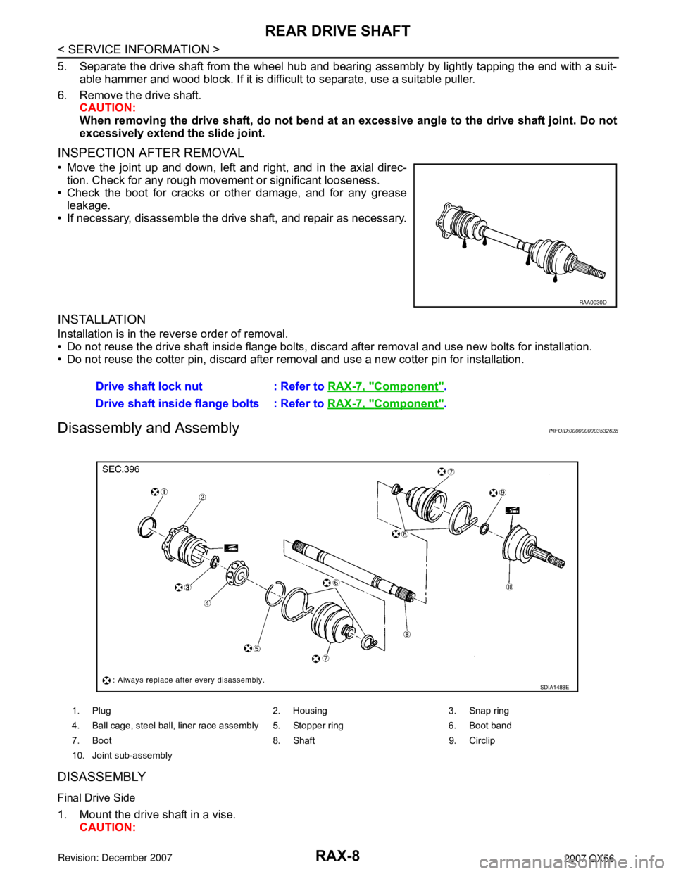
1. Plug 2. Housing 3. Snap ring
4. Ball cage, steel ball, liner race assembly 5. Stopper ring 6. Boot band
7. Boot 8. Shaft 9. Circlip
10. Joint sub-assembly
SDIA1488E
Page 2613 of 3061
REAR SUSPENSION ASSEMBLY
RSU-23
< SERVICE INFORMATION >
C
D
F
G
H
I
J
K
L
MA
B
RSU
N
O
P
Wheel AlignmentInspectionINFOID:0000000003532671
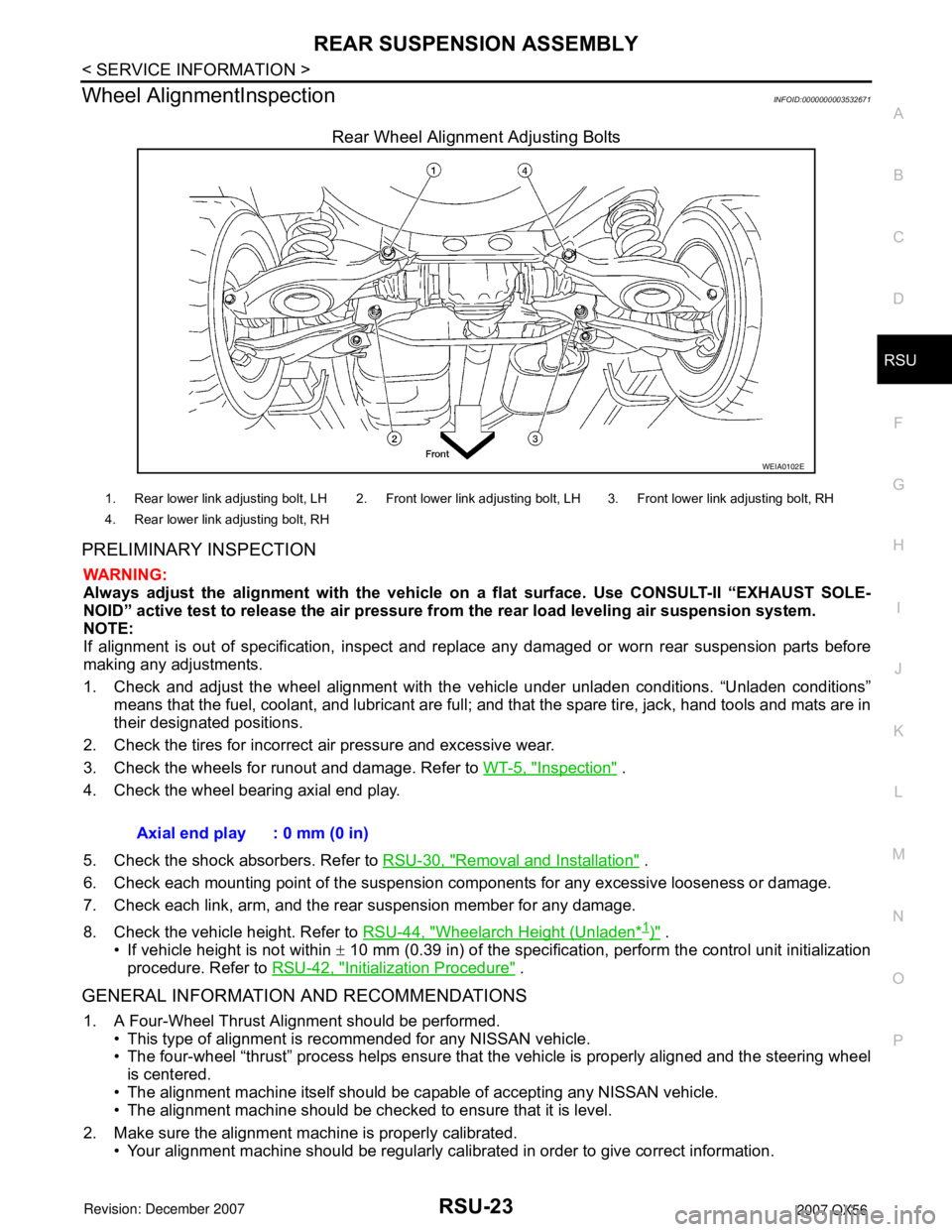
Rear Wheel Alignment Adjusting Bolts
PRELIMINARY INSPECTION
WARNING:
Always adjust the alignment with the vehicle on a flat surface. Use CONSULT-II “EXHAUST SOLE-
NOID” active test to release the air pressure from the rear load leveling air suspension system.
NOTE:
If alignment is out of specification, inspect and replace any damaged or worn rear suspension parts before
making any adjustments.
1. Check and adjust the wheel alignment with the vehicle under unladen conditions. “Unladen conditions”
means that the fuel, coolant, and lubricant are full; and that the spare tire, jack, hand tools and mats are in
their designated positions.
2. Check the tires for incorrect air pressure and excessive wear.
3. Check the wheels for runout and damage. Refer to WT-5, "
Inspection" .
4. Check the wheel bearing axial end play.
5. Check the shock absorbers. Refer to RSU-30, "
Removal and Installation" .
6. Check each mounting point of the suspension components for any excessive looseness or damage.
7. Check each link, arm, and the rear suspension member for any damage.
8. Check the vehicle height. Refer to RSU-44, "
Wheelarch Height (Unladen*1)" .
• If vehicle height is not within ± 10 mm (0.39 in) of the specification, perform the control unit initialization
procedure. Refer to RSU-42, "
Initialization Procedure" .
GENERAL INFORMATION AND RECOMMENDATIONS
1. A Four-Wheel Thrust Alignment should be performed.
• This type of alignment is recommended for any NISSAN vehicle.
• The four-wheel “thrust” process helps ensure that the vehicle is properly aligned and the steering wheel
is centered.
• The alignment machine itself should be capable of accepting any NISSAN vehicle.
• The alignment machine should be checked to ensure that it is level.
2. Make sure the alignment machine is properly calibrated.
• Your alignment machine should be regularly calibrated in order to give correct information.
WEIA0102E
1. Rear lower link adjusting bolt, LH 2. Front lower link adjusting bolt, LH 3. Front lower link adjusting bolt, RH
4. Rear lower link adjusting bolt, RH
Axial end play : 0 mm (0 in)
Page 2619 of 3061
REAR SUSPENSION MEMBER
RSU-29
< SERVICE INFORMATION >
C
D
F
G
H
I
J
K
L
MA
B
RSU
N
O
P
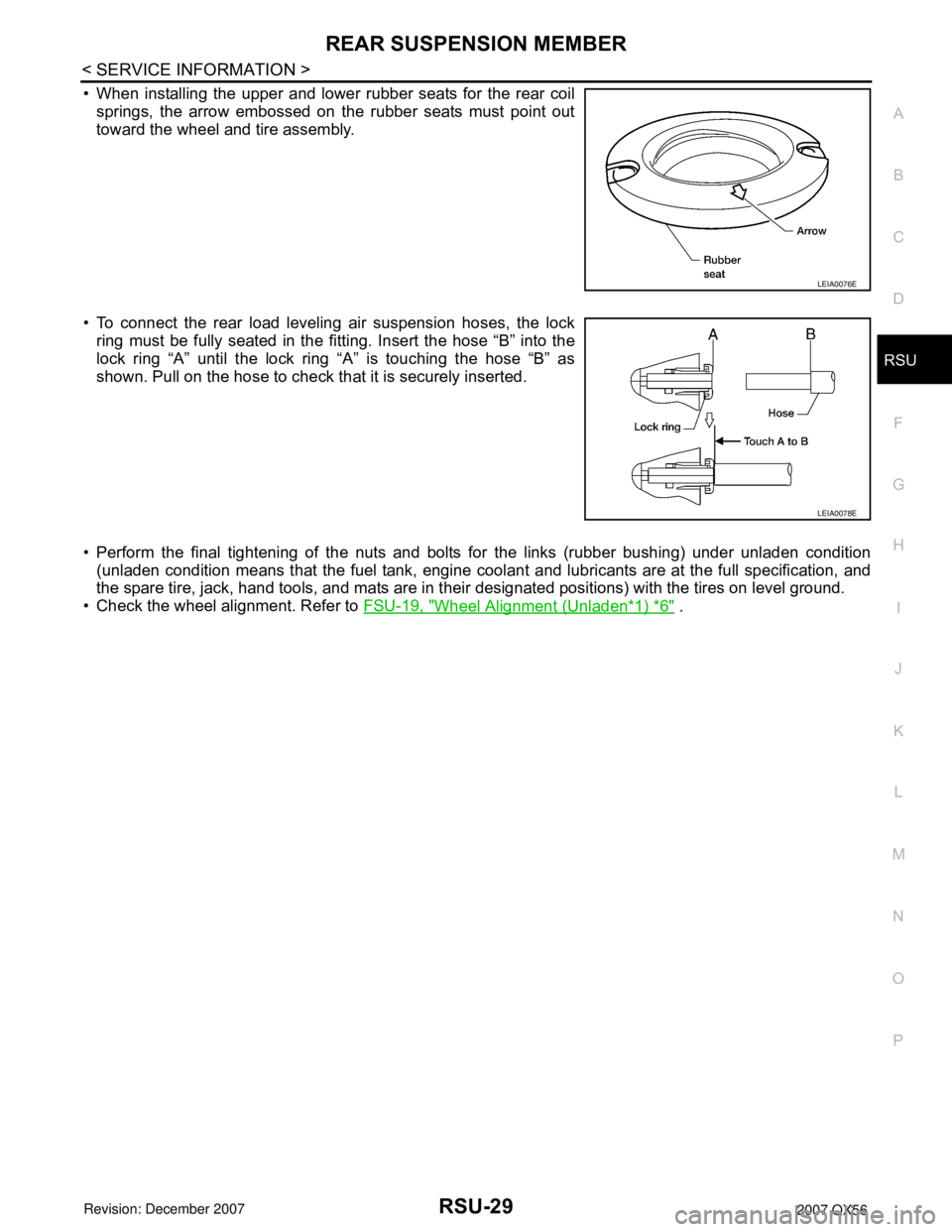
• When installing the upper and lower rubber seats for the rear coil
springs, the arrow embossed on the rubber seats must point out
toward the wheel and tire assembly.
• To connect the rear load leveling air suspension hoses, the lock
ring must be fully seated in the fitting. Insert the hose “B” into the
lock ring “A” until the lock ring “A” is touching the hose “B” as
shown. Pull on the hose to check that it is securely inserted.
• Perform the final tightening of the nuts and bolts for the links (rubber bushing) under unladen condition
(unladen condition means that the fuel tank, engine coolant and lubricants are at the full specification, and
the spare tire, jack, hand tools, and mats are in their designated positions) with the tires on level ground.
• Check the wheel alignment. Refer to FSU-19, "
Wheel Alignment (Unladen*1) *6" .
LEIA0076E
LEIA0078E
Page 2620 of 3061
RSU-30
< SERVICE INFORMATION >
SHOCK ABSORBER
SHOCK ABSORBER
Removal and InstallationINFOID:0000000003532673
REMOVAL
1. Remove the wheel and tire assembly using power tool. Refer to WT-7, "Rotation".
2. Use CONSULT-II “EXHAUST SOLENOID” active test to release the air pressure from the rear load level-
ing air suspension system.
3. Remove the four clips and remove the rear fender protector, front.
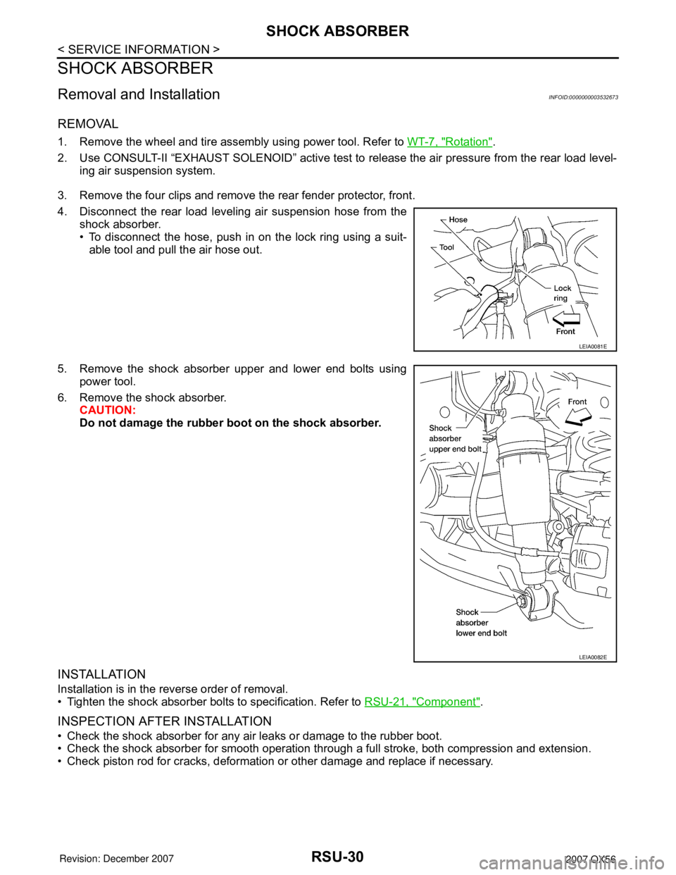
4. Disconnect the rear load leveling air suspension hose from the
shock absorber.
• To disconnect the hose, push in on the lock ring using a suit-
able tool and pull the air hose out.
5. Remove the shock absorber upper and lower end bolts using
power tool.
6. Remove the shock absorber.
CAUTION:
Do not damage the rubber boot on the shock absorber.
INSTALLATION
Installation is in the reverse order of removal.
• Tighten the shock absorber bolts to specification. Refer to RSU-21, "
Component".
INSPECTION AFTER INSTALLATION
• Check the shock absorber for any air leaks or damage to the rubber boot.
• Check the shock absorber for smooth operation through a full stroke, both compression and extension.
• Check piston rod for cracks, deformation or other damage and replace if necessary.
LEIA0081E
LEIA0082E
Page 2622 of 3061

RSU-32
< SERVICE INFORMATION >
SUSPENSION ARM
• Check the ball joint. Replace the suspension arm assembly if any
of the following conditions exist:
- Ball stud is worn.
- Joint is hard to swing.
- Play in axial direction is excessive.
INSTALLATION
Installation is in the reverse order of removal.
• Tighten the nuts and bolts to specification. Refer to RSU-21, "
Component" .
• Perform the final tightening of the nuts and bolts for the links (rubber bushing) under unladen condition
(unladen condition means that the fuel tank, engine coolant and lubricants are at the full specification, and
the spare tire, jack, hand tools, and mats are in their designated positions) with the tires on level ground.
• Check the wheel alignment. Refer to RSU-23, "
Wheel AlignmentInspection" . Swinging force “A” : Refer to RSU-43, "
Ball Joint" .
Turning force “B” : Refer to RSU-43, "
Ball Joint" .
Vertical end play “C” : Refer to RSU-43, "
Ball Joint" .
SFA858A
Page 2624 of 3061
RSU-34
< SERVICE INFORMATION >
FRONT LOWER LINK
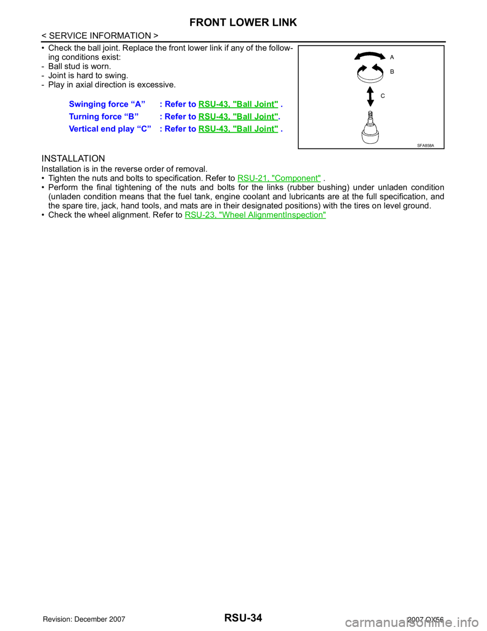
• Check the ball joint. Replace the front lower link if any of the follow-
ing conditions exist:
- Ball stud is worn.
- Joint is hard to swing.
- Play in axial direction is excessive.
INSTALLATION
Installation is in the reverse order of removal.
• Tighten the nuts and bolts to specification. Refer to RSU-21, "
Component" .
• Perform the final tightening of the nuts and bolts for the links (rubber bushing) under unladen condition
(unladen condition means that the fuel tank, engine coolant and lubricants are at the full specification, and
the spare tire, jack, hand tools, and mats are in their designated positions) with the tires on level ground.
• Check the wheel alignment. Refer to RSU-23, "
Wheel AlignmentInspection"
Swinging force “A” : Refer to RSU-43, "Ball Joint" .
Turning force “B” : Refer to RSU-43, "
Ball Joint".
Vertical end play “C” : Refer to RSU-43, "
Ball Joint" .
SFA858A
Page 2626 of 3061
RSU-36
< SERVICE INFORMATION >
REAR LOWER LINK & COIL SPRING
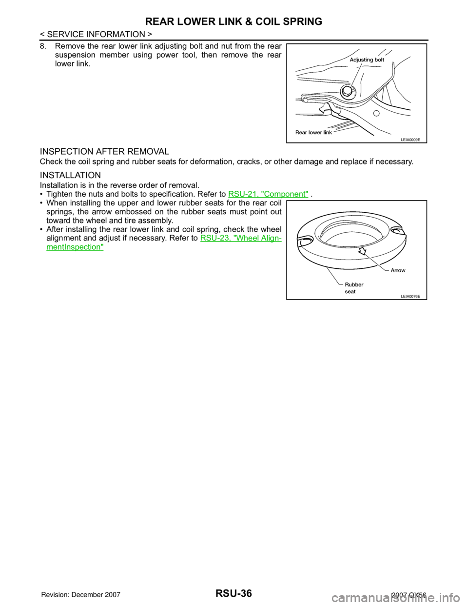
8. Remove the rear lower link adjusting bolt and nut from the rear
suspension member using power tool, then remove the rear
lower link.
INSPECTION AFTER REMOVAL
Check the coil spring and rubber seats for deformation, cracks, or other damage and replace if necessary.
INSTALLATION
Installation is in the reverse order of removal.
• Tighten the nuts and bolts to specification. Refer to RSU-21, "
Component" .
• When installing the upper and lower rubber seats for the rear coil
springs, the arrow embossed on the rubber seats must point out
toward the wheel and tire assembly.
• After installing the rear lower link and coil spring, check the wheel
alignment and adjust if necessary. Refer to RSU-23, "
Wheel Align-
mentInspection"
LEIA0009E
LEIA0076E
Page 2805 of 3061

DRIVER AIR BAG MODULE
SRS-35
< SERVICE INFORMATION >
C
D
E
F
G
I
J
K
L
MA
B
SRS
N
O
P
DRIVER AIR BAG MODULE
Removal and InstallationINFOID:0000000003532873
REMOVAL
CAUTION:
• Do not attempt to repair or replace damaged direct-connect SRS component connectors. If a driver
air bag direct-connect harness connector is damaged, the spiral cable must be replaced.
• Before servicing the SRS, turn ignition switch OFF, disconnect both battery cables and wait at least
3 minutes.
• When servicing the SRS, do not work from directly in front of air bag module.
1. Disconnect the negative and positive battery cables, then wait at least 3 minutes.
2. Remove the left and right side lids and bolts.
3. Lift the driver air bag module from the steering wheel.
4. Disconnect the horn connector and air bag harness, then remove the driver air bag module.
• For removal/installation of the direct-connect SRS connectors, refer to SRS-6, "
Direct-connect SRS
Component Connectors" .
CAUTION:
• When servicing the SRS, do not work from directly in front of air bag module.
• Always place air bag module with pad side facing upward.
• Do not insert any foreign objects (screwdriver, etc.) into air
bag module or harness connectors.
• Do not disassemble air bag module.
• Do not use old bolts after removal; replace with new bolts.
• Do not expose the air bag module to temperatures exceeding
90°C (194°F).
1. Horn harness 2. Steering wheel hook 3. Inflator harness
4. Side lids RH/LH 5. Driver air bag module 6. Steering wheel
WHIA0159E
LHIA0052E