height INFINITI QX56 2007 Factory Owner's Guide
[x] Cancel search | Manufacturer: INFINITI, Model Year: 2007, Model line: QX56, Model: INFINITI QX56 2007Pages: 3061, PDF Size: 64.56 MB
Page 1839 of 3061
CYLINDER HEAD
EM-69
< SERVICE INFORMATION >
C
D
E
F
G
H
I
J
K
L
MA
EM
N
P O
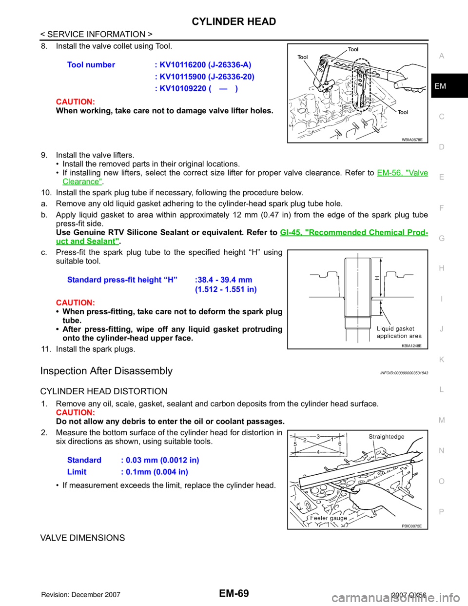
8. Install the valve collet using Tool.
CAUTION:
When working, take care not to damage valve lifter holes.
9. Install the valve lifters.
• Install the removed parts in their original locations.
• If installing new lifters, select the correct size lifter for proper valve clearance. Refer to EM-56, "
Va l v e
Clearance".
10. Install the spark plug tube if necessary, following the procedure below.
a. Remove any old liquid gasket adhering to the cylinder-head spark plug tube hole.
b. Apply liquid gasket to area within approximately 12 mm (0.47 in) from the edge of the spark plug tube
press-fit side.
Use Genuine RTV Silicone Sealant or equivalent. Refer to GI-45, "
Recommended Chemical Prod-
uct and Sealant".
c. Press-fit the spark plug tube to the specified height “H” using
suitable tool.
CAUTION:
• When press-fitting, take care not to deform the spark plug
tube.
• After press-fitting, wipe off any liquid gasket protruding
onto the cylinder-head upper face.
11. Install the spark plugs.
Inspection After DisassemblyINFOID:0000000003531543
CYLINDER HEAD DISTORTION
1. Remove any oil, scale, gasket, sealant and carbon deposits from the cylinder head surface.
CAUTION:
Do not allow any debris to enter the oil or coolant passages.
2. Measure the bottom surface of the cylinder head for distortion in
six directions as shown, using suitable tools.
• If measurement exceeds the limit, replace the cylinder head.
VALVE DIMENSIONS
Tool number : KV10116200 (J-26336-A)
: KV10115900 (J-26336-20)
: KV10109220 ( — )
WBIA0578E
Standard press-fit height “H” :38.4 - 39.4 mm
(1.512 - 1.551 in)
KBIA1248E
Standard : 0.03 mm (0.0012 in)
Limit : 0.1mm (0.004 in)
PBIC0075E
Page 1843 of 3061
CYLINDER HEAD
EM-73
< SERVICE INFORMATION >
C
D
E
F
G
H
I
J
K
L
MA
EM
N
P O
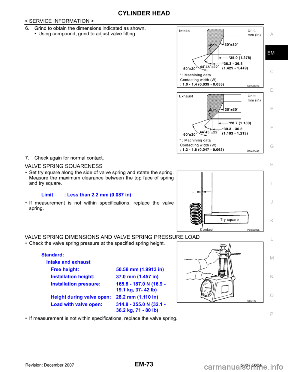
6. Grind to obtain the dimensions indicated as shown.
• Using compound, grind to adjust valve fitting.
7. Check again for normal contact.
VALVE SPRING SQUARENESS
• Set try square along the side of valve spring and rotate the spring.
Measure the maximum clearance between the top face of spring
and try square.
• If measurement is not within specifications, replace the valve
spring.
VALVE SPRING DIMENSIONS AND VALVE SPRING PRESSURE LOAD
• Check the valve spring pressure at the specified spring height.
• If measurement is not within specifications, replace the valve spring.
KBIA2531E
KBIA2544E
Limit : Less than 2.2 mm (0.087 in)
PBIC0080E
Standard:
Intake and exhaust
Free height: 50.58 mm (1.9913 in)
Installation height: 37.0 mm (1.457 in)
Installation pressure: 165.8 - 187.0 N (16.9 -
19.1 kg, 37- 42 lb)
Height during valve open: 28.2 mm (1.110 in)
Load with valve open: 314.8 - 355.0 N (32.1 -
36.2 kg, 71 - 80 lb)
SEM113
Page 1871 of 3061
CYLINDER BLOCK
EM-101
< SERVICE INFORMATION >
C
D
E
F
G
H
I
J
K
L
MA
EM
N
P O
• If measured value exceeds the repair limit, select main bearings referring to the main bearing inside diame-
ter and crankshaft journal diameter, so that the oil clearance satisfies the standard. Refer to EM-86, "
How to
Select Piston and Bearing".
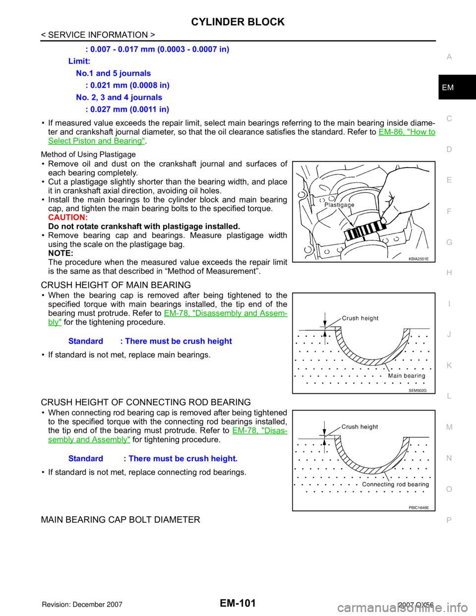
Method of Using Plastigage
• Remove oil and dust on the crankshaft journal and surfaces of
each bearing completely.
• Cut a plastigage slightly shorter than the bearing width, and place
it in crankshaft axial direction, avoiding oil holes.
• Install the main bearings to the cylinder block and main bearing
cap, and tighten the main bearing bolts to the specified torque.
CAUTION:
Do not rotate crankshaft with plastigage installed.
• Remove bearing cap and bearings. Measure plastigage width
using the scale on the plastigage bag.
NOTE:
The procedure when the measured value exceeds the repair limit
is the same as that described in “Method of Measurement”.
CRUSH HEIGHT OF MAIN BEARING
• When the bearing cap is removed after being tightened to the
specified torque with main bearings installed, the tip end of the
bearing must protrude. Refer to EM-78, "
Disassembly and Assem-
bly" for the tightening procedure.
• If standard is not met, replace main bearings.
CRUSH HEIGHT OF CONNECTING ROD BEARING
• When connecting rod bearing cap is removed after being tightened
to the specified torque with the connecting rod bearings installed,
the tip end of the bearing must protrude. Refer to EM-78, "
Disas-
sembly and Assembly" for tightening procedure.
• If standard is not met, replace connecting rod bearings.
MAIN BEARING CAP BOLT DIAMETER
: 0.007 - 0.017 mm (0.0003 - 0.0007 in)
Limit:
No.1 and 5 journals
: 0.021 mm (0.0008 in)
No. 2, 3 and 4 journals
: 0.027 mm (0.0011 in)
KBIA2551E
Standard : There must be crush height
SEM502G
Standard : There must be crush height.
PBIC1646E
Page 1874 of 3061
EM-104
< SERVICE INFORMATION >
SERVICE DATA AND SPECIFICATIONS (SDS)
Unit: mm (in)
SPARK PLUG
CAMSHAFT AND CAMSHAFT BEARING
Unit: mm (in)
*: Total indicator reading
Valve Lifter
Unit: mm (in)
Valve Clearance
Unit: mm (in)
*: Approximately 80°C (176°F)
Available Valve Lifter
ItemsLimit
Surface distortion Exhaust manifold 0.3 (0.012)
MakeNGK
Standard typeDIFR5A-11
Gap (Nominal)1.1 mm (0.043 in)
ItemsStandard
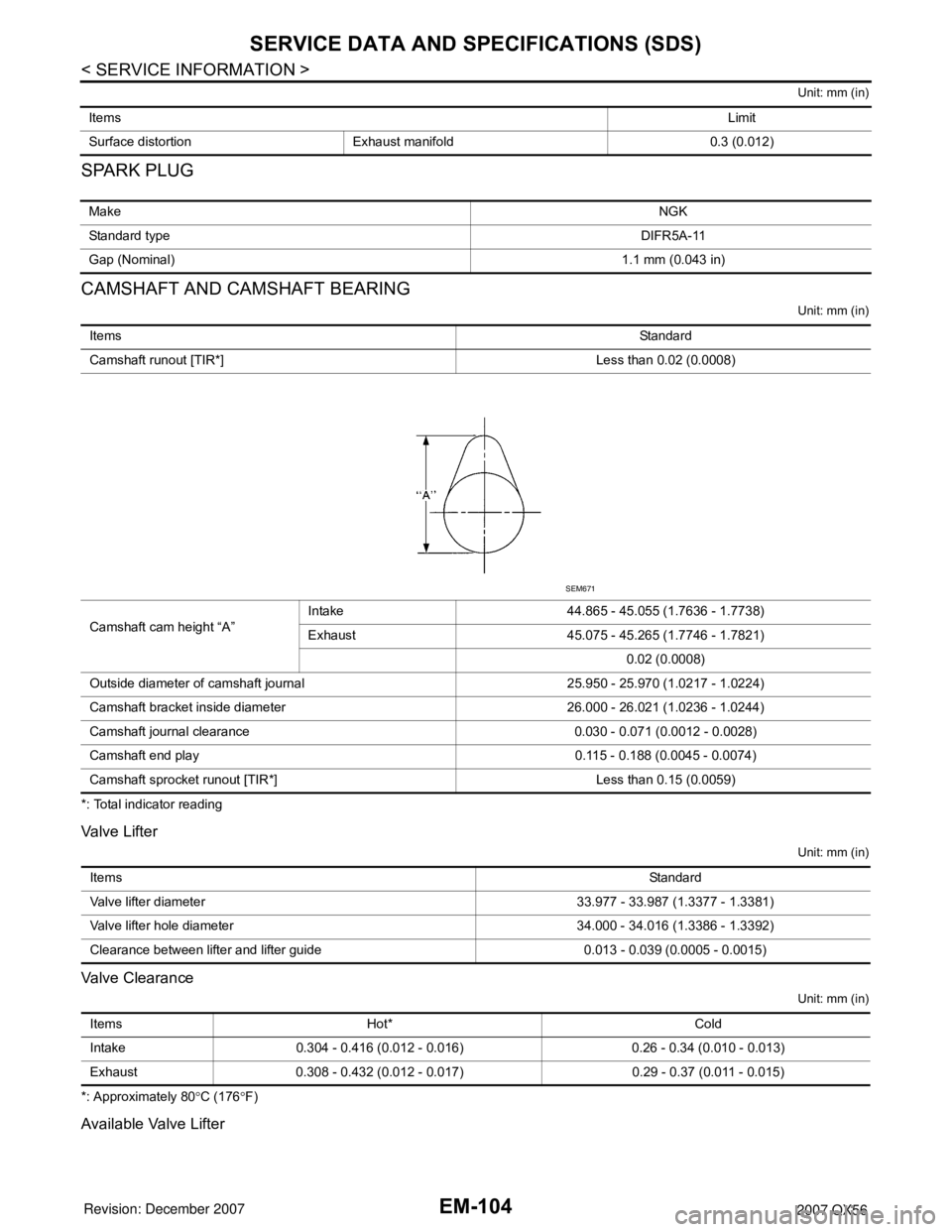
Camshaft runout [TIR*] Less than 0.02 (0.0008)
Camshaft cam height “A”Intake 44.865 - 45.055 (1.7636 - 1.7738)
Exhaust 45.075 - 45.265 (1.7746 - 1.7821)
0.02 (0.0008)
Outside diameter of camshaft journal 25.950 - 25.970 (1.0217 - 1.0224)
Camshaft bracket inside diameter 26.000 - 26.021 (1.0236 - 1.0244)
Camshaft journal clearance 0.030 - 0.071 (0.0012 - 0.0028)
Camshaft end play 0.115 - 0.188 (0.0045 - 0.0074)
Camshaft sprocket runout [TIR*] Less than 0.15 (0.0059)
SEM671
ItemsStandard
Valve lifter diameter 33.977 - 33.987 (1.3377 - 1.3381)
Valve lifter hole diameter 34.000 - 34.016 (1.3386 - 1.3392)
Clearance between lifter and lifter guide 0.013 - 0.039 (0.0005 - 0.0015)
Items Hot* Cold
Intake 0.304 - 0.416 (0.012 - 0.016) 0.26 - 0.34 (0.010 - 0.013)
Exhaust 0.308 - 0.432 (0.012 - 0.017) 0.29 - 0.37 (0.011 - 0.015)
Page 1876 of 3061
EM-106
< SERVICE INFORMATION >
SERVICE DATA AND SPECIFICATIONS (SDS)
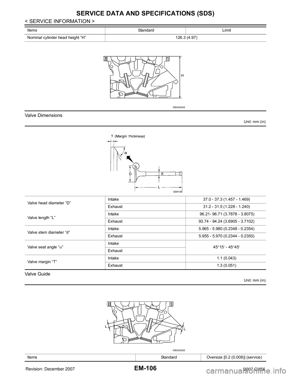
Valve Dimensions
Unit: mm (in)
Valve Guide
Unit: mm (in)
Nominal cylinder head height “H” 126.3 (4.97) Items Standard Limit
KBIA2554E
Valve head diameter “D”Intake 37.0 - 37.3 (1.457 - 1.469)
Exhaust 31.2 - 31.5 (1.228 - 1.240)
Valve length “L”Intake 96.21- 96.71 (3.7878 - 3.8075)
Exhaust 93.74 - 94.24 (3.6905 - 3.7102)
Valve stem diameter “d”Intake 5.965 - 5.980 (0.2348 - 0.2354)
Exhaust 5.955 - 5.970 (0.2344 - 0.2350)
Valve seat angle “α”Intake
45°15′ - 45°45′
Exhaust
Valve margin “T”Intake 1.1 (0.043)
Exhaust 1.3 (0.051)
SEM188
Items Standard Oversize [0.2 (0.008)] (service)
KBIA2555E
Page 1877 of 3061
SERVICE DATA AND SPECIFICATIONS (SDS)
EM-107
< SERVICE INFORMATION >
C
D
E
F
G
H
I
J
K
L
MA
EM
N
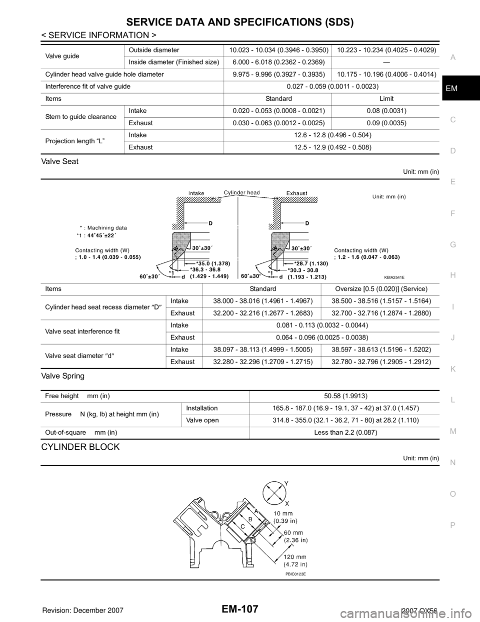
P O Valve Seat
Unit: mm (in)
Va l v e Sp r i n g
CYLINDER BLOCK
Unit: mm (in)
Valve guideOutside diameter 10.023 - 10.034 (0.3946 - 0.3950) 10.223 - 10.234 (0.4025 - 0.4029)
Inside diameter (Finished size) 6.000 - 6.018 (0.2362 - 0.2369) —
Cylinder head valve guide hole diameter 9.975 - 9.996 (0.3927 - 0.3935) 10.175 - 10.196 (0.4006 - 0.4014)
Interference fit of valve guide 0.027 - 0.059 (0.0011 - 0.0023)
Items Standard Limit
Stem to guide clearanceIntake 0.020 - 0.053 (0.0008 - 0.0021) 0.08 (0.0031)
Exhaust 0.030 - 0.063 (0.0012 - 0.0025) 0.09 (0.0035)
Projection length “L”Intake 12.6 - 12.8 (0.496 - 0.504)
Exhaust 12.5 - 12.9 (0.492 - 0.508)
Items Standard Oversize [0.5 (0.020)] (Service)
Cylinder head seat recess diameter ″D″Intake 38.000 - 38.016 (1.4961 - 1.4967) 38.500 - 38.516 (1.5157 - 1.5164)
Exhaust 32.200 - 32.216 (1.2677 - 1.2683) 32.700 - 32.716 (1.2874 - 1.2880)
Valve seat interference fitIntake 0.081 - 0.113 (0.0032 - 0.0044)
Exhaust 0.064 - 0.096 (0.0025 - 0.0038)
Valve seat diameter ″d″Intake 38.097 - 38.113 (1.4999 - 1.5005) 38.597 - 38.613 (1.5196 - 1.5202)
Exhaust 32.280 - 32.296 (1.2709 - 1.2715) 32.780 - 32.796 (1.2905 - 1.2912)
KBIA2541E
Free height mm (in)50.58 (1.9913)
Pressure N (kg, lb) at height mm (in)Installation 165.8 - 187.0 (16.9 - 19.1, 37 - 42) at 37.0 (1.457)
Valve open 314.8 - 355.0 (32.1 - 36.2, 71 - 80) at 28.2 (1.110)
Out-of-square mm (in) Less than 2.2 (0.087)
PBIC0123E
Page 1886 of 3061
EX-4
< SERVICE INFORMATION >
EXHAUST SYSTEM
Remove exhaust system components using power tool.
INSTALLATION
Installation is in the reverse order of removal.
CAUTION:
• Always replace exhaust gaskets with new ones when reassembling.
• Before installing a new heated oxygen sensor, clean and lube the exhaust tube threads using Tool.
• Discard any heated oxygen sensor which has been dropped from a height of more than 0.5 m (19.7
in) onto a hard surface such as a concrete floor; replace with a new one.
• Do not over-torque the heated oxygen sensor. Doing so may damage the heated oxygen sensor,
resulting in the MIL coming on.
• If any mounting insulator is badly deformed, repair or replace it. If deposits such as mud pile up on
the mounting insulators, clean and inspect them.
• Temporarily tighten the nuts on the exhaust manifold side and the bolts on the vehicle side. Check
each part for interference with other components, and then tighten the nuts and bolts to specifica-
tion.
INSPECTION AFTER INSTALLATION
• With the engine running, check exhaust tube joints for gas leakage and unusual noises.
• Check to ensure that mounting brackets and mounting rubbers are installed properly and free from undue
stress. Improper installation could result in excessive noise and vibration. Tool number
A : — (J-43897-18)
B : — (J-43897-12)
Page 1913 of 3061
FFD-14
< SERVICE INFORMATION >
FRONT FINAL DRIVE ASSEMBLY
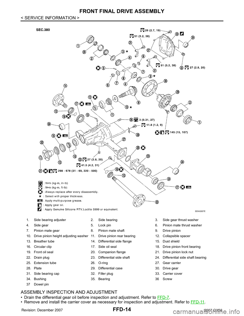
ASSEMBLY INSPECTION AND ADJUSTMENT
• Drain the differential gear oil before inspection and adjustment. Refer to FFD-7.
• Remove and install the carrier cover as necessary for inspection and adjustment. Refer to FFD-11
.
1. Side bearing adjuster 2. Side bearing 3. Side gear thrust washer
4. Side gear 5. Lock pin 6. Pinion mate thrust washer
7. Pinion mate gear 8. Pinion mate shaft 9. Drive pinion
10. Drive pinion height adjusting washer 11. Drive pinion rear bearing 12. Collapsible spacer
13. Breather tube 14. Differential side flange 15. Dust shield
16. Circular clip 17. Side oil seal 18. Drive pinion front bearing
19. Front oil seal 20. Companion flange 21. Drive pinion lock nut
22. Drain plug 23. Differential side shaft 24. Differential side shaft bearing
25. Extension tube 26. O-ring 27. Gear carrier
28. Plate 29. Differential case 30. Drive gear
31. Side bearing cap 32. Filler plug 33. Carrier cover
34. Bushing 35. Bearing 36 Screw
37 Dowel pin
SDIA3207E
Page 1915 of 3061
FFD-16
< SERVICE INFORMATION >
FRONT FINAL DRIVE ASSEMBLY
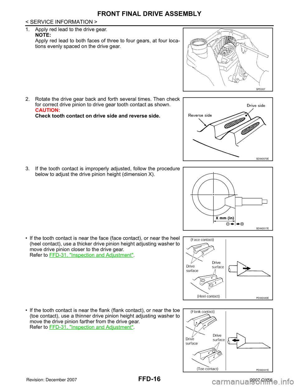
1. Apply red lead to the drive gear.
NOTE:
Apply red lead to both faces of three to four gears, at four loca-
tions evenly spaced on the drive gear.
2. Rotate the drive gear back and forth several times. Then check
for correct drive pinion to drive gear tooth contact as shown.
CAUTION:
Check tooth contact on drive side and reverse side.
3. If the tooth contact is improperly adjusted, follow the procedure
below to adjust the drive pinion height (dimension X).
• If the tooth contact is near the face (face contact), or near the heel
(heel contact), use a thicker drive pinion height adjusting washer to
move drive pinion closer to the drive gear.
Refer to FFD-31, "
Inspection and Adjustment".
• If the tooth contact is near the flank (flank contact), or near the toe
(toe contact), use a thinner drive pinion height adjusting washer to
move the drive pinion farther from the drive gear.
Refer to FFD-31, "
Inspection and Adjustment".
SPD357
SDIA0570E
SDIA0517E
PDIA0440E
PDIA0441E
Page 1920 of 3061
FRONT FINAL DRIVE ASSEMBLY
FFD-21
< SERVICE INFORMATION >
C
E
F
G
H
I
J
K
L
MA
B
FFD
N
O
P Drive Pinion Assembly
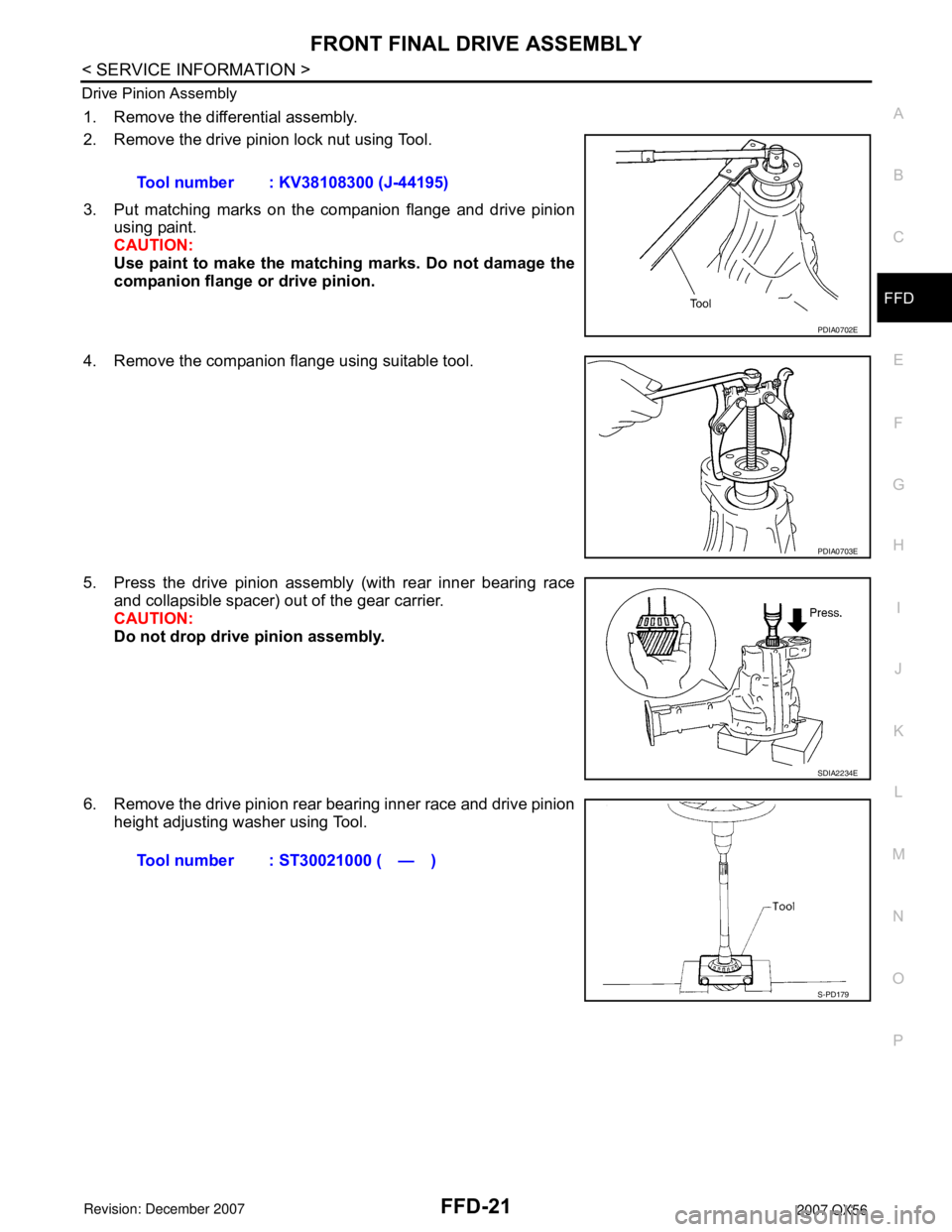
1. Remove the differential assembly.
2. Remove the drive pinion lock nut using Tool.
3. Put matching marks on the companion flange and drive pinion
using paint.
CAUTION:
Use paint to make the matching marks. Do not damage the
companion flange or drive pinion.
4. Remove the companion flange using suitable tool.
5. Press the drive pinion assembly (with rear inner bearing race
and collapsible spacer) out of the gear carrier.
CAUTION:
Do not drop drive pinion assembly.
6. Remove the drive pinion rear bearing inner race and drive pinion
height adjusting washer using Tool.Tool number : KV38108300 (J-44195)
PDIA0702E
PDIA0703E
SDIA2234E
Tool number : ST30021000 ( — )
S-PD179