height INFINITI QX56 2007 Factory Workshop Manual
[x] Cancel search | Manufacturer: INFINITI, Model Year: 2007, Model line: QX56, Model: INFINITI QX56 2007Pages: 3061, PDF Size: 64.56 MB
Page 2014 of 3061

GI-48
< SERVICE INFORMATION >
IDENTIFICATION INFORMATION
ENGINE SERIAL NUMBER
TRANSFER SERIAL NUMBER
AUTOMATIC TRANSMISSION NUMBER
DimensionsINFOID:0000000003531505
Unit: mm (in)
Wheels & TiresINFOID:0000000003531506
LAIA0044E
LAIA0048E
PAIA0054E
Drive type2WD 4WD
Overall length 5255 (206.9) 5255 (206.9)
Overall width 2001 (78.8) 2001 (78.8)
Overall height (with roof rack) 1976.8 (77.0) 1997.7 (77.8)
Front tread width 1725 (67.9) 1725 (67.9)
Rear tread width 1725 (67.9) 1725 (67.9)
Wheelbase 3130 (123.2) 3130 (123.2)
Minimum Running Ground Clearance (at front suspen-
sion)With standard
undercover254.8 (10.03) 273.7 (10.77)
With oil pan skid
plate250.5 (9.86) 269.5 (10.61)
Page 2109 of 3061

IDX-5
A
C
D
E
F
G
H
I
J
K
L B
IDX
ALPHABETICAL INDEX
Grease .............................................................. MA-11
Ground distribution ............................................ PG-31
H
H/AIM - Wiring diagram ...................................... LT-51
H/LAMP - Wiring diagram .................................... LT-9
Handling precautions for plastics ..................... BL-179
Harness connector ............................................ PG-68
Harness layout .................................................. PG-41
Hazard warning lamp ......................................... LT-63
Headlamp ............................................................. LT-5
Headlamp aiming control ................................... LT-51
Headlamp leveler - See Headlamp aiming control . LT-
51
Headlamp removal and installation .................... LT-25
Heated oxygen sensor 2 (bank 1) .... EC-276, EC-287,
EC-300
Heated oxygen sensor 2 (bank 2) .... EC-276, EC-287,
EC-300
Heated oxygen sensor 2 heater (bank 1) ........ EC-181
Heated oxygen sensor 2 heater (bank 2) ........ EC-181
Heated seat ....................................................... SE-82
Heater and cooling unit (Heater core) . ATC-157, ATC-
160
Heater unit (heater core) ............... ATC-157, ATC-160
Height (Dimensions) ........................................... GI-51
HFC134a (R134a) system identification ........... ATC-6
HFC134a (R134a) system precaution ............... ATC-5
HFC134a (R134a) system service procedure ATC-175
HFC134a (R134a) system service tools ......... ATC-14
HFC134a system service equipment precaution ATC-
11
High and low reverse clutch solenoid valve .... AT-147,
AT-149
Homelink universal transceiver ........................ BL-146
Horn ................................................................ WW-48
HORN - Wiring diagram .................................. WW-48
How to erase DTC for OBD system .................. EC-63
HSEAT - Wiring diagram ................................... SE-84
I
IATS - Wiring diagram ..................................... EC-215
ICC - Wiring diagram ....................................... ACS-20
ICC/BS - Wiring diagram ................................. EC-565
ICC/SW - Wiring diagram ................................ EC-550
ICCBOF - Wiring diagram ............................... EC-672
Identification plate .............................................. GI-49
Idle air volume learning ..................................... EC-80
Idle speed .............................................. EC-73, EC-78
Idle speed control (ISC) .................... EC-466, EC-468
Ignition coil .......................................... EM-28, EC-679
Ignition control system .................................... EC-679
Ignition key hole illumination ............................ LT-110
Ignition timing ........................................ EC-73, EC-78
IGNSYS - Wiring diagram ............................... EC-680
ILL - Wiring diagram ......................................... LT-136
Illumination ....................................................... LT-130
In vehicle sensor ........................... ATC-141, ATC-150
In-cabin Microfilter ............................................. MA-21
INJECT - Wiring diagram ................................. EC-660
Injector ............................................................. EC-659
Input clutch solenoid valve ................. AT-135, AT-137
Instrument panel .................................................. IP-10
Intake air temperature sensor ............ EC-214, EC-234
Intake door control linkage adjustment . ATC-85, ATC-
88
Intake door motor ........................... ATC-83, ATC-164
Intake manifold .................................................. EM-17
Intake sensor ................................ ATC-146, ATC-152
Intake valve timing control (Bank 1) ................ EC-161
Intake valve timing control (Bank 2) ................ EC-161
Intake valve timing control position sensor (Bank 1) ....
EC-492
Intake valve timing control position sensor (Bank 2) ....
EC-492
Intake valve timing control solenoid valve (Bank 1) EC-
189
Intake valve timing control solenoid valve (Bank 2) EC-
189
Integrated homelink transmitter - See Homelink univer-
sal tranceiver .................................................... BL-146
Intelligent cruise control (ICC) system ............... ACS-6
Interior ................................................................. EI-35
Interior lamp ...................................................... LT-110
Interior lamp on-off control ................................ LT-111
Internal gear (Transfer) ....................... TF-149, TF-176
IPDM (Intelligent power distribution module engine
room) ................................................................. PG-18
IVCB1 - Wiring diagram ................................... EC-190
IVCB2 - Wiring diagram ................................... EC-192
IVCSB1 - Wiring diagram ................................ EC-493
IVCSB2 - Wiring diagram ................................ EC-495
IVIS (Infiniti vehicle immobilizer system) .......... BL-127
IVIS (Infiniti vehicle immobilizer system) precautions ...
GI-3
IVTB1 - Wiring diagram ................................... EC-164
IVTB2 - Wiring diagram ................................... EC-166
J
Jacking points ..................................................... GI-42
Junction box (J/B) .............................................. PG-76
K
Key illumination ................................................ LT-111
KEYLES - Wiring diagram .................................. BL-45
Knock sensor (KS) ........................................... EC-357
KS - Wiring diagram ........................................ EC-358
L
Laser beam aiming adjustment ....................... ACS-12
Length (Dimensions) .......................................... GI-51
License lamp ...................................................... LT-89
Lifting points ....................................................... GI-43
Page 2262 of 3061

FRONT FOG LAMP
LT-55
< SERVICE INFORMATION >
C
D
E
F
G
H
I
J
L
MA
B
LT
N
O
P
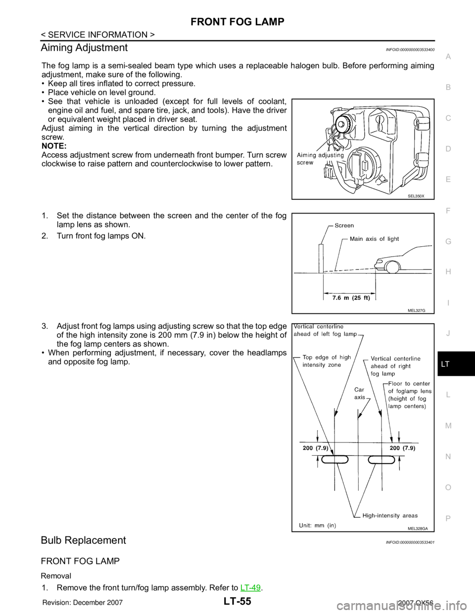
Aiming AdjustmentINFOID:0000000003533400
The fog lamp is a semi-sealed beam type which uses a replaceable halogen bulb. Before performing aiming
adjustment, make sure of the following.
• Keep all tires inflated to correct pressure.
• Place vehicle on level ground.
• See that vehicle is unloaded (except for full levels of coolant,
engine oil and fuel, and spare tire, jack, and tools). Have the driver
or equivalent weight placed in driver seat.
Adjust aiming in the vertical direction by turning the adjustment
screw.
NOTE:
Access adjustment screw from underneath front bumper. Turn screw
clockwise to raise pattern and counterclockwise to lower pattern.
1. Set the distance between the screen and the center of the fog
lamp lens as shown.
2. Turn front fog lamps ON.
3. Adjust front fog lamps using adjusting screw so that the top edge
of the high intensity zone is 200 mm (7.9 in) below the height of
the fog lamp centers as shown.
• When performing adjustment, if necessary, cover the headlamps
and opposite fog lamp.
Bulb ReplacementINFOID:0000000003533401
FRONT FOG LAMP
Removal
1. Remove the front turn/fog lamp assembly. Refer to LT- 4 9.
SEL350X
MEL327G
MEL328GA
Page 2552 of 3061

RF-20
< SERVICE INFORMATION >
SUNROOF
Fitting Adjustment
INFOID:0000000003533112
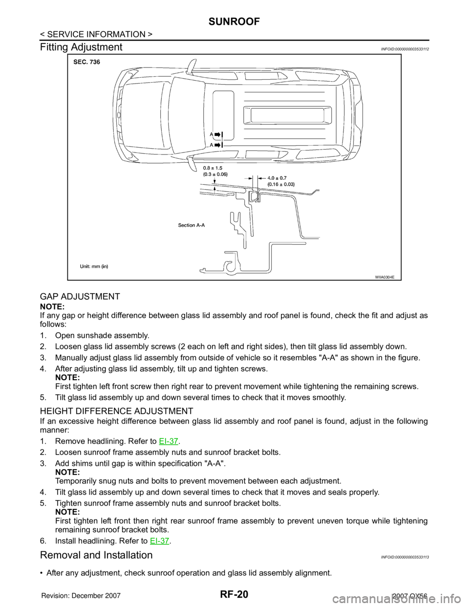
GAP ADJUSTMENT
NOTE:
If any gap or height difference between glass lid assembly and roof panel is found, check the fit and adjust as
follows:
1. Open sunshade assembly.
2. Loosen glass lid assembly screws (2 each on left and right sides), then tilt glass lid assembly down.
3. Manually adjust glass lid assembly from outside of vehicle so it resembles "A-A" as shown in the figure.
4. After adjusting glass lid assembly, tilt up and tighten screws.
NOTE:
First tighten left front screw then right rear to prevent movement while tightening the remaining screws.
5. Tilt glass lid assembly up and down several times to check that it moves smoothly.
HEIGHT DIFFERENCE ADJUSTMENT
If an excessive height difference between glass lid assembly and roof panel is found, adjust in the following
manner:
1. Remove headlining. Refer to EI-37
.
2. Loosen sunroof frame assembly nuts and sunroof bracket bolts.
3. Add shims until gap is within specification "A-A".
NOTE:
Temporarily snug nuts and bolts to prevent movement between each adjustment.
4. Tilt glass lid assembly up and down several times to check that it moves and seals properly.
5. Tighten sunroof frame assembly nuts and sunroof bracket bolts.
NOTE:
First tighten left front then right rear sunroof frame assembly to prevent uneven torque while tightening
remaining sunroof bracket bolts.
6. Install headlining. Refer to EI-37
.
Removal and InstallationINFOID:0000000003533113
• After any adjustment, check sunroof operation and glass lid assembly alignment.
WIIA0304E
Page 2554 of 3061

RF-22
< SERVICE INFORMATION >
SUNROOF
SUNROOF UNIT
Removal
CAUTION:
• Always work with a helper.
• When taking sunroof unit out, use shop cloths to protect the seats and trim from damage.
• After installing the sunroof unit and glass lid assembly, check gap adjustment to make sure there is
no malfunction.
1. Remove headlining. Refer to EI-37
.
2. Remove the sunroof glass lid assembly. Refer to "GLASS LID ASSEMBLY".
3. Remove overhead console bracket.
4. Disconnect front and rear drain hoses.
5. Remove front sunroof frame assembly bolts.
6. Remove rear sunroof bracket bolts.
7. Remove the sunroof frame assembly side bolts, then the sunroof unit.
Installation
1. Position the sunroof frame assembly and install the side bolts.
2. Install the sunroof brackets and bolts.
3. Install the front sunroof frame assembly bolts.
4. Connect front and rear drain hoses.
5. Install the overhead console bracket.
6. Install the sunroof glass lid assembly. Refer to "GLASS LID ASSEMBLY".
NOTE:
Adjust sunroof glass lid assembly gap and height, refer to RF-20, "
Fitting Adjustment".
7. Install headlining. Refer to EI-37
.
GLASS LID ASSEMBLY
Removal
1. Open sunshade assembly.
NOTE:
Be sure glass lid assembly is fully closed.
2. Remove side cover LH and RH.
3. Remove the glass lid assembly screws at the sunroof frame
assembly.
4. Remove the glass lid assembly.
Installation
1. Position glass lid assembly to sunroof frame assembly.
2. Install glass lid assembly screws.
NOTE:
First tighten left front screw, then right rear to prevent movement while tightening the remaining screws.
1. Glass lid assembly 2. Wind deflector 3. Rear drain hoses
4. Shade stoppers 5. Sunroof bracket 6. Sunshade assembly
7. Front drain hoses 8. Sunroof motor assembly 9. Sunroof frame assembly
10. Overhead console bracket 11. Side cover LH 12. Side cover RH
WIIA0252E
Page 2573 of 3061

RFD-16
< SERVICE INFORMATION >
REAR FINAL DRIVE ASSEMBLY
1. Drive pinion lock nut 2. Companion flange 3. Front oil seal
4. Drive pinion front bearing 5. Collapsible spacer 6. Drive pinion rear bearing
7. Drive pinion height adjusting washer 8. Drive pinion 9. Gear carrier
10. Drive gear 11. Pinion mate shaft 12. Lock pin
13. Pinion mate gear 14. Pinion mate thrust washer 15. Side gear
16. Side gear thrust washer 17. Differential case 18. Side bearing
WDIA0191E
Page 2575 of 3061

RFD-18
< SERVICE INFORMATION >
REAR FINAL DRIVE ASSEMBLY
1. Apply red lead to the drive gear.
NOTE:
Apply red lead to both faces of three to four gears, at four loca-
tions evenly spaced on the drive gear.
2. Rotate the drive gear back and forth several times. Then check
for correct drive pinion to drive gear tooth contact as shown.
CAUTION:
Check tooth contact on drive side and reverse side.
3. If the tooth contact is improperly adjusted, follow the procedure
below to adjust the pinion height (dimension X).
• If the tooth contact is near the face (face contact), or near the heel
(heel contact), use a thicker drive pinion height adjusting washers
to move the drive pinion closer to the drive gear.
Refer to RFD-32, "
Inspection and Adjustment".
• If the tooth contact is near the flank (flank contact), or near the toe
(toe contact), use a thinner drive pinion height adjusting washers to
move the drive pinion farther from the drive gear.
Refer to RFD-32, "
Inspection and Adjustment".
SPD357
SDIA0570E
SDIA0517E
PDIA0440E
PDIA0441E
Page 2580 of 3061

REAR FINAL DRIVE ASSEMBLY
RFD-23
< SERVICE INFORMATION >
C
E
F
G
H
I
J
K
L
MA
B
RFD
N
O
P
5. Press the drive pinion assembly (with rear inner bearing race
and collapsible spacer) out of the gear carrier.
CAUTION:
Do not drop drive pinion assembly.
6. Remove the front oil seal.
CAUTION:
Do not damage gear carrier.
7. Remove the drive pinion front bearing inner race.
8. Remove the drive pinion rear bearing inner race and drive pinion
height adjusting washer using Tool.
9. Remove the drive pinion front and rear bearing outer races by
tapping them uniformly using suitable tool.
CAUTION:
Do not damage gear carrier.
INSPECTION AFTER DISASSEMBLY
Clean the disassembled parts. Then inspect the parts for wear or damage. If wear or damage are found, follow
the measures below.
Drive Pinion and Drive Gear
• If the drive pinion and drive gear teeth do not mesh or line-up correctly, determine the cause and adjust,
repair, or replace as necessary.
• If the drive pinion or drive gear are worn, cracked, damaged, pitted or chipped (by friction) noticeably,
replace with new drive pinion and drive gear.
• Drive pinion and drive gear are supplied in matched sets only. Matching numbers on both drive pinion and
drive gear are etched for verification. If a new drive pinion and drive gear set are being used, verify the num-
bers of each drive pinion and drive gear before proceeding with assembly.
Bearing
• If bearings are chipped (by friction), pitted, worn, rusted, scratched, or unusual noise is coming from bearing,
replace with new bearing assembly (as a new set).
• Bearing must be replaced with a new one whenever disassembled.
Side Gear and Pinion Mate Gear
• If any cracks or damage are found on the surface of the teeth, replace with new one.
• If any worn or chipped marks are found on the side of the side gear and pinion mate gear which contact the
thrust washer, replace with new one.
• Replace both side gear and pinion mate gear as a set when replacing side gear or pinion mate gear.
Side Gear Thrust Washer and Pinion Mate Thrust Washer
• If any chips (by friction), damage, or unusual wear are found, replace with new one.
SPD892
Tool number: : ST30021000 ( — )
S-PD179
SDIA0817E
Page 2583 of 3061

RFD-26
< SERVICE INFORMATION >
REAR FINAL DRIVE ASSEMBLY
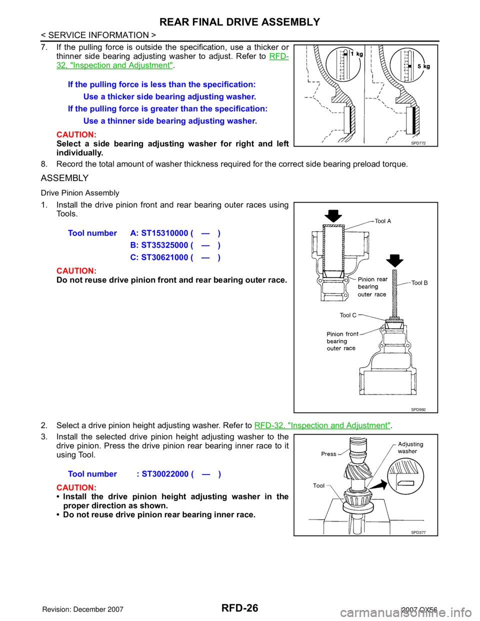
7. If the pulling force is outside the specification, use a thicker or
thinner side bearing adjusting washer to adjust. Refer to RFD-
32, "Inspection and Adjustment".
CAUTION:
Select a side bearing adjusting washer for right and left
individually.
8. Record the total amount of washer thickness required for the correct side bearing preload torque.
ASSEMBLY
Drive Pinion Assembly
1. Install the drive pinion front and rear bearing outer races using
Tools.
CAUTION:
Do not reuse drive pinion front and rear bearing outer race.
2. Select a drive pinion height adjusting washer. Refer to RFD-32, "
Inspection and Adjustment".
3. Install the selected drive pinion height adjusting washer to the
drive pinion. Press the drive pinion rear bearing inner race to it
using Tool.
CAUTION:
• Install the drive pinion height adjusting washer in the
proper direction as shown.
• Do not reuse drive pinion rear bearing inner race.If the pulling force is less than the specification:
Use a thicker side bearing adjusting washer.
If the pulling force is greater than the specification:
Use a thinner side bearing adjusting washer.
SPD772
Tool number A: ST15310000 ( — )
B: ST35325000 ( — )
C: ST30621000 ( — )
SPD992
Tool number : ST30022000 ( — )
SPD377
Page 2590 of 3061

SERVICE DATA AND SPECIFICATIONS (SDS)
RFD-33
< SERVICE INFORMATION >
C
E
F
G
H
I
J
K
L
MA
B
RFD
N
O
P
Unit: mm (in)
*: Always check with the Parts Department for the latest parts information.
Drive Pinion Height Adjusting Washer
Unit: mm (in)
*: Always check with the Parts Department for the latest parts information.
Side Bearing Adjusting Washer
Unit: mm (in)
*: Always check with the Parts Department for the latest parts information.Thickness Part number*
1.75 (0.0688)
1.80 (0.0708)
1.85 (0.0728)38424 7S000
38424 7S001
38424 7S002
Thickness Part number* Thickness Part number*
2.59 (0.1020)
2.61 (0.1028)
2.63 (0.1035)
2.65 (0.1043)
2.67 (0.1051)
2.69 (0.1059)
2.71 (0.1067)
2.73 (0.1075)
2.75 (0.1083)
2.77 (0.1091)38154 40P00
38154 40P01
38154 40P02
38154 40P03
38154 40P04
38154 40P05
38154 40P06
38154 40P07
38154 40P08
38154 40P092.79 (0.1098)
2.81 (0.1106)
2.83 (0.1114)
2.85 (0.1122)
2.87 (0.1130)
2.89 (0.1138)
2.91 (0.1146)
2.93 (0.1154)
2.95 (0.1161)
2.97 (0.1169)38154 40P10
38154 40P11
38154 40P12
38154 40P13
38154 40P14
38154 40P15
38154 40P16
38154 40P17
38154 40P18
38154 40P19
Thickness Part number* Thickness Part number*
2.00 (0.0787)
2.05 (0.0807)
2.10 (0.0827)
2.15 (0.0846)
2.20 (0.0866)
2.25 (0.0886)
2.30 (0.0906)38453 40P00
38453 40P01
38453 40P02
38453 40P03
38453 40P04
38453 40P05
38453 40P062.35 (0.0925)
2.40 (0.0945)
2.45 (0.0965)
2.50 (0.0984)
2.55 (0.1004)
2.60 (0.1024)38453 40P07
38453 40P08
38453 40P09
38453 40P10
38453 40P11
38453 40P12