height INFINITI QX56 2007 Factory Workshop Manual
[x] Cancel search | Manufacturer: INFINITI, Model Year: 2007, Model line: QX56, Model: INFINITI QX56 2007Pages: 3061, PDF Size: 64.56 MB
Page 1923 of 3061
FFD-24
< SERVICE INFORMATION >
FRONT FINAL DRIVE ASSEMBLY
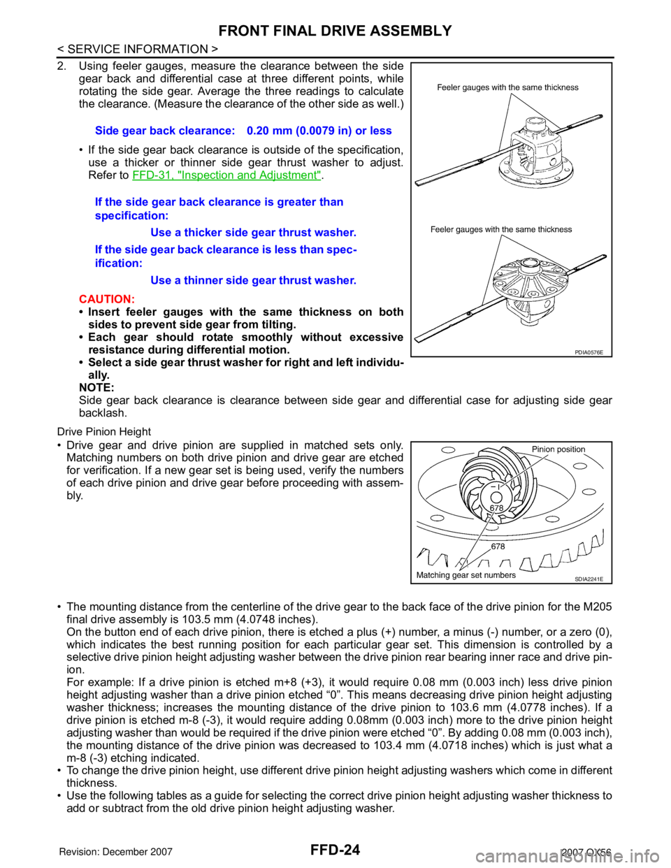
2. Using feeler gauges, measure the clearance between the side
gear back and differential case at three different points, while
rotating the side gear. Average the three readings to calculate
the clearance. (Measure the clearance of the other side as well.)
• If the side gear back clearance is outside of the specification,
use a thicker or thinner side gear thrust washer to adjust.
Refer to FFD-31, "
Inspection and Adjustment".
CAUTION:
• Insert feeler gauges with the same thickness on both
sides to prevent side gear from tilting.
• Each gear should rotate smoothly without excessive
resistance during differential motion.
• Select a side gear thrust washer for right and left individu-
ally.
NOTE:
Side gear back clearance is clearance between side gear and differential case for adjusting side gear
backlash.
Drive Pinion Height
• Drive gear and drive pinion are supplied in matched sets only.
Matching numbers on both drive pinion and drive gear are etched
for verification. If a new gear set is being used, verify the numbers
of each drive pinion and drive gear before proceeding with assem-
bly.
• The mounting distance from the centerline of the drive gear to the back face of the drive pinion for the M205
final drive assembly is 103.5 mm (4.0748 inches).
On the button end of each drive pinion, there is etched a plus (+) number, a minus (-) number, or a zero (0),
which indicates the best running position for each particular gear set. This dimension is controlled by a
selective drive pinion height adjusting washer between the drive pinion rear bearing inner race and drive pin-
ion.
For example: If a drive pinion is etched m+8 (+3), it would require 0.08 mm (0.003 inch) less drive pinion
height adjusting washer than a drive pinion etched “0”. This means decreasing drive pinion height adjusting
washer thickness; increases the mounting distance of the drive pinion to 103.6 mm (4.0778 inches). If a
drive pinion is etched m-8 (-3), it would require adding 0.08mm (0.003 inch) more to the drive pinion height
adjusting washer than would be required if the drive pinion were etched “0”. By adding 0.08 mm (0.003 inch),
the mounting distance of the drive pinion was decreased to 103.4 mm (4.0718 inches) which is just what a
m-8 (-3) etching indicated.
• To change the drive pinion height, use different drive pinion height adjusting washers which come in different
thickness.
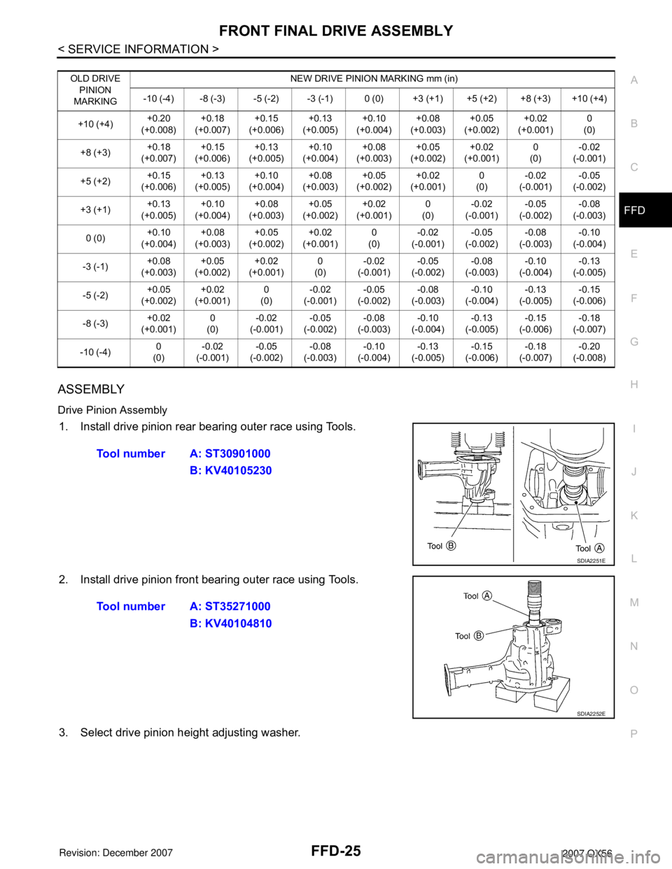
• Use the following tables as a guide for selecting the correct drive pinion height adjusting washer thickness to
add or subtract from the old drive pinion height adjusting washer.Side gear back clearance: 0.20 mm (0.0079 in) or less
If the side gear back clearance is greater than
specification:
Use a thicker side gear thrust washer.
If the side gear back clearance is less than spec-
ification:
Use a thinner side gear thrust washer.
PDIA0576E
SDIA2241E
Page 1924 of 3061
FRONT FINAL DRIVE ASSEMBLY
FFD-25
< SERVICE INFORMATION >
C
E
F
G
H
I
J
K
L
MA
B
FFD
N
O
P
ASSEMBLY
Drive Pinion Assembly
1. Install drive pinion rear bearing outer race using Tools.
2. Install drive pinion front bearing outer race using Tools.
3. Select drive pinion height adjusting washer.
OLD DRIVE
PINION
MARKINGNEW DRIVE PINION MARKING mm (in)
-10 (-4) -8 (-3) -5 (-2) -3 (-1) 0 (0) +3 (+1) +5 (+2) +8 (+3) +10 (+4)
+10 (+4)+0.20
(+0.008)+0.18
(+0.007) +0.15
(+0.006)+0.13
(+0.005)+0.10
(+0.004)+0.08
(+0.003)+0.05
(+0.002)+0.02
(+0.001)0
(0)
+8 (+3)+0.18
(+0.007)+0.15
(+0.006)+0.13
(+0.005)+0.10
(+0.004)+0.08
(+0.003)+0.05
(+0.002)+0.02
(+0.001)0
(0)-0.02
(-0.001)
+5 (+2)+0.15
(+0.006)+0.13
(+0.005)+0.10
(+0.004)+0.08
(+0.003)+0.05
(+0.002)+0.02
(+0.001)0
(0)-0.02
(-0.001)-0.05
(-0.002)
+3 (+1)+0.13
(+0.005)+0.10
(+0.004)+0.08
(+0.003)+0.05
(+0.002)+0.02
(+0.001)0
(0)-0.02
(-0.001)-0.05
(-0.002)-0.08
(-0.003)
0 (0)+0.10
(+0.004)+0.08
(+0.003)+0.05
(+0.002)+0.02
(+0.001)0
(0)-0.02
(-0.001)-0.05
(-0.002)-0.08
(-0.003)-0.10
(-0.004)
-3 (-1)+0.08
(+0.003)+0.05
(+0.002)+0.02
(+0.001)0
(0)-0.02
(-0.001)-0.05
(-0.002)-0.08
(-0.003)-0.10
(-0.004)-0.13
(-0.005)
-5 (-2)+0.05
(+0.002)+0.02
(+0.001)0
(0)-0.02
(-0.001)-0.05
(-0.002)-0.08
(-0.003)-0.10
(-0.004)-0.13
(-0.005)-0.15
(-0.006)
-8 (-3)+0.02
(+0.001)0
(0)-0.02
(-0.001)-0.05
(-0.002)-0.08
(-0.003)-0.10
(-0.004)-0.13
(-0.005)-0.15
(-0.006)-0.18
(-0.007)
-10 (-4)0
(0)-0.02
(-0.001)-0.05
(-0.002)-0.08
(-0.003)-0.10
(-0.004)-0.13
(-0.005)-0.15
(-0.006)-0.18
(-0.007)-0.20
(-0.008)
Tool number A: ST30901000
B: KV40105230
SDIA2251E
Tool number A: ST35271000
B: KV40104810
SDIA2252E
Page 1925 of 3061
FFD-26
< SERVICE INFORMATION >
FRONT FINAL DRIVE ASSEMBLY
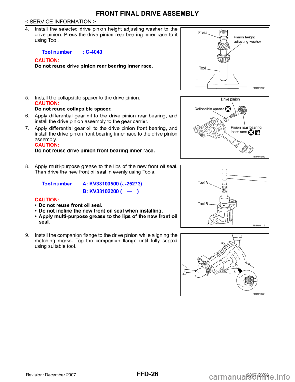
4. Install the selected drive pinion height adjusting washer to the
drive pinion. Press the drive pinion rear bearing inner race to it
using Tool.
CAUTION:
Do not reuse drive pinion rear bearing inner race.
5. Install the collapsible spacer to the drive pinion.
CAUTION:
Do not reuse collapsible spacer.
6. Apply differential gear oil to the drive pinion rear bearing, and
install the drive pinion assembly to the gear carrier.
7. Apply differential gear oil to the drive pinion front bearing, and
install the drive pinion front bearing inner race to the drive pinion
assembly.
CAUTION:
Do not reuse drive pinion front bearing inner race.
8. Apply multi-purpose grease to the lips of the new front oil seal.
Then drive the new front oil seal in evenly using Tools.
CAUTION:
• Do not reuse front oil seal.
• Do not incline the new front oil seal when installing.
• Apply multi-purpose grease to the lips of the new front oil
seal.
9. Install the companion flange to the drive pinion while aligning the
matching marks. Tap the companion flange until fully seated
using suitable tool.Tool number : C-4040
SDIA2253E
PDIA0708E
Tool number A: KV38100500 (J-25273)
B: KV38102200 ( — )
PDIA0717E
SDIA2266E
Page 1930 of 3061
SERVICE DATA AND SPECIFICATIONS (SDS)
FFD-31
< SERVICE INFORMATION >
C
E
F
G
H
I
J
K
L
MA
B
FFD
N
O
P
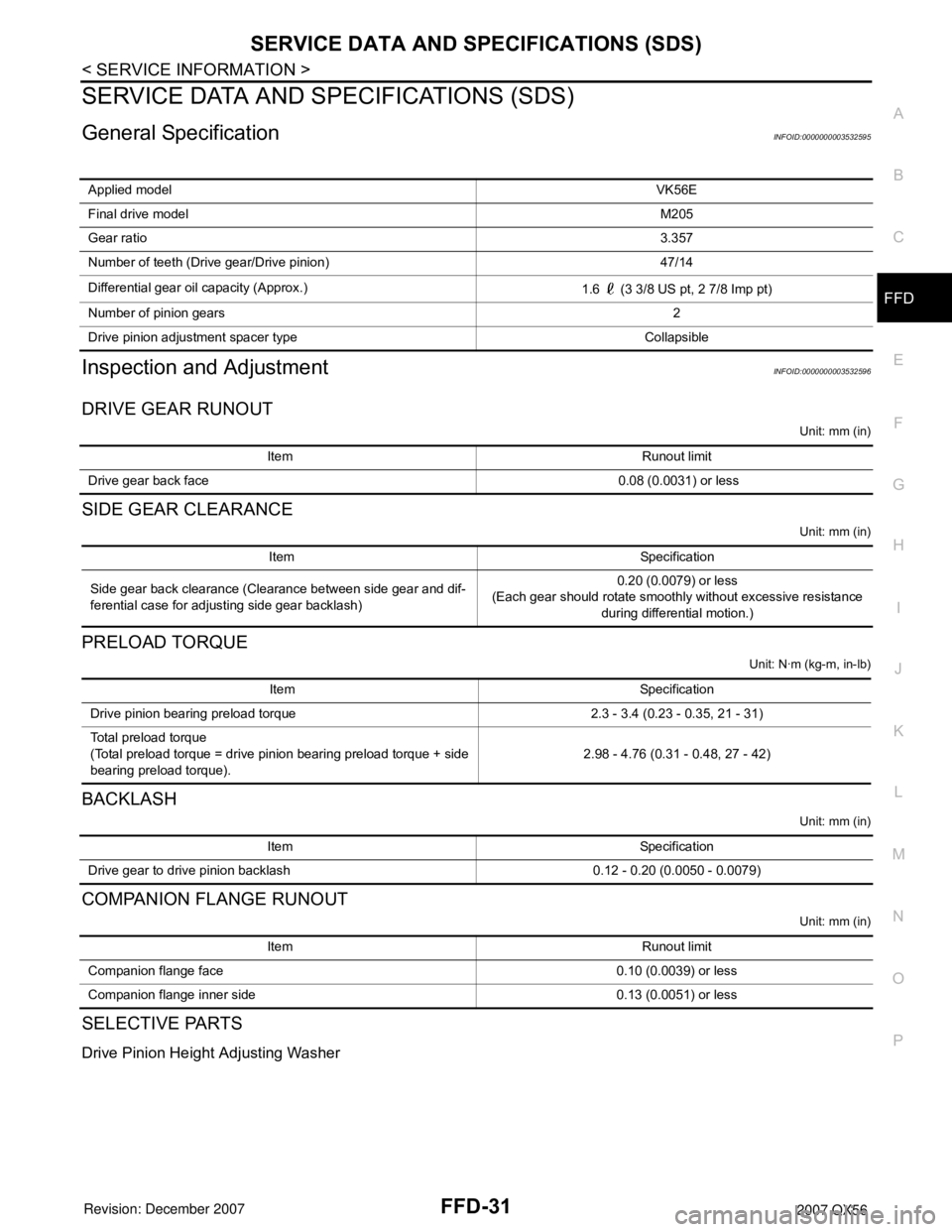
SERVICE DATA AND SPECIFICATIONS (SDS)
General SpecificationINFOID:0000000003532595
Inspection and AdjustmentINFOID:0000000003532596
DRIVE GEAR RUNOUT
Unit: mm (in)
SIDE GEAR CLEARANCE
Unit: mm (in)
PRELOAD TORQUE
Unit: N·m (kg-m, in-lb)
BACKLASH
Unit: mm (in)
COMPANION FLANGE RUNOUT
Unit: mm (in)
SELECTIVE PARTS
Drive Pinion Height Adjusting Washer
Applied modelVK56E
Final drive modelM205
Gear ratio3.357
Number of teeth (Drive gear/Drive pinion) 47/14
Differential gear oil capacity (Approx.)
1.6 (3 3/8 US pt, 2 7/8 Imp pt)
Number of pinion gears2
Drive pinion adjustment spacer type Collapsible
Item Runout limit
Drive gear back face 0.08 (0.0031) or less
Item Specification
Side gear back clearance (Clearance between side gear and dif-
ferential case for adjusting side gear backlash)0.20 (0.0079) or less
(Each gear should rotate smoothly without excessive resistance
during differential motion.)
Item Specification
Drive pinion bearing preload torque 2.3 - 3.4 (0.23 - 0.35, 21 - 31)
Total preload torque
(Total preload torque = drive pinion bearing preload torque + side
bearing preload torque).2.98 - 4.76 (0.31 - 0.48, 27 - 42)
Item Specification
Drive gear to drive pinion backlash 0.12 - 0.20 (0.0050 - 0.0079)
Item Runout limit
Companion flange face 0.10 (0.0039) or less
Companion flange inner side 0.13 (0.0051) or less
Page 1947 of 3061
FSU-1
SUSPENSION
C
D
F
G
H
I
J
K
L
M
SECTION FSU
A
B
FSU
N
O
PCONTENTS
FRONT SUSPENSION
SERVICE INFORMATION ............................2
PRECAUTIONS ...................................................2
Precaution .................................................................2
PREPARATION ...................................................3
Special Service Tool .................................................3
Commercial Service Tool ..........................................3
NOISE, VIBRATION AND HARSHNESS
(NVH) TROUBLESHOOTING .............................
4
NVH Troubleshooting Chart ......................................4
FRONT SUSPENSION ASSEMBLY ...................5
Component ................................................................5
ON-VEHICLE SERVICE ......................................6
Front Suspension Parts .............................................6
Front Wheel Alignment ..............................................6
COIL SPRING AND SHOCK ABSORBER ........10
Removal and Installation .........................................10
Disassembly and Assembly ....................................10
STABILIZER BAR ..............................................12
Removal and Installation .........................................12
UPPER LINK .....................................................13
Removal and Installation .........................................13
LOWER LINK ....................................................14
Removal and Installation .........................................14
UPPER BALL JOINT AND LOWER BALL
JOINT ................................................................
15
Removal and Installation .........................................15
Inspection ................................................................15
KNUCKLE .........................................................17
On-Vehicle Inspection and Service .........................17
Removal and Installation .........................................17
SERVICE DATA AND SPECIFICATIONS
(SDS) .................................................................
19
General Specification ..............................................19
Spring Free Height ..................................................19
Wheel Alignment (Unladen*1) *6 .............................19
Ball Joint ..................................................................20
Wheelarch Height (Unladen*1) ................................20
Page 1952 of 3061
FSU-6
< SERVICE INFORMATION >
ON-VEHICLE SERVICE
ON-VEHICLE SERVICE
Front Suspension PartsINFOID:0000000003532636
Check front suspension parts for excessive play, cracks, wear and
other damage.
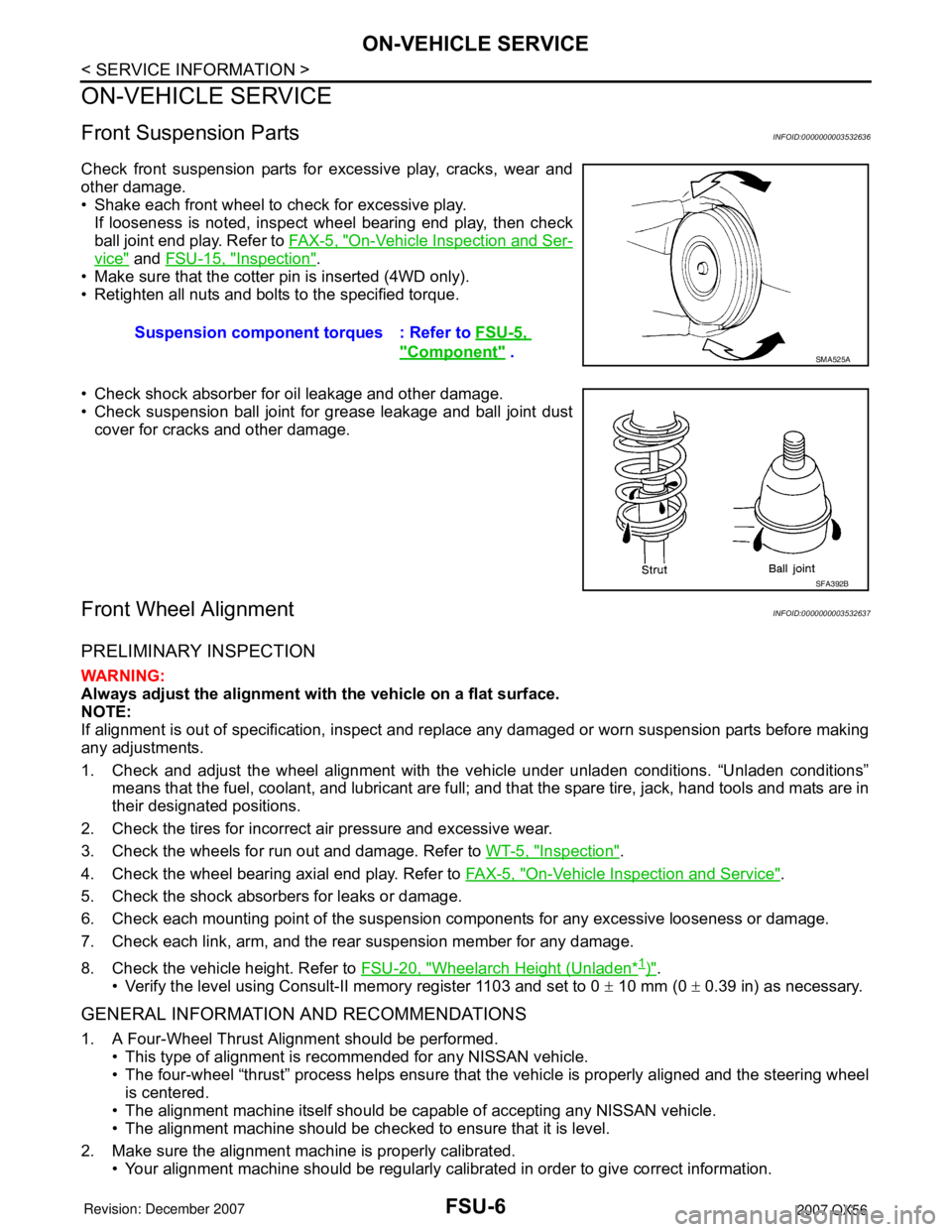
• Shake each front wheel to check for excessive play.
If looseness is noted, inspect wheel bearing end play, then check
ball joint end play. Refer to FA X - 5 , "
On-Vehicle Inspection and Ser-
vice" and FSU-15, "Inspection".
• Make sure that the cotter pin is inserted (4WD only).
• Retighten all nuts and bolts to the specified torque.
• Check shock absorber for oil leakage and other damage.
• Check suspension ball joint for grease leakage and ball joint dust
cover for cracks and other damage.
Front Wheel AlignmentINFOID:0000000003532637
PRELIMINARY INSPECTION
WARNING:
Always adjust the alignment with the vehicle on a flat surface.
NOTE:
If alignment is out of specification, inspect and replace any damaged or worn suspension parts before making
any adjustments.
1. Check and adjust the wheel alignment with the vehicle under unladen conditions. “Unladen conditions”
means that the fuel, coolant, and lubricant are full; and that the spare tire, jack, hand tools and mats are in
their designated positions.
2. Check the tires for incorrect air pressure and excessive wear.
3. Check the wheels for run out and damage. Refer to WT-5, "
Inspection".
4. Check the wheel bearing axial end play. Refer to FA X - 5 , "
On-Vehicle Inspection and Service".
5. Check the shock absorbers for leaks or damage.
6. Check each mounting point of the suspension components for any excessive looseness or damage.
7. Check each link, arm, and the rear suspension member for any damage.
8. Check the vehicle height. Refer to FSU-20, "
Wheelarch Height (Unladen*1)".
• Verify the level using Consult-II memory register 1103 and set to 0 ± 10 mm (0 ± 0.39 in) as necessary.
GENERAL INFORMATION AND RECOMMENDATIONS
1. A Four-Wheel Thrust Alignment should be performed.
• This type of alignment is recommended for any NISSAN vehicle.
• The four-wheel “thrust” process helps ensure that the vehicle is properly aligned and the steering wheel
is centered.
• The alignment machine itself should be capable of accepting any NISSAN vehicle.
• The alignment machine should be checked to ensure that it is level.
2. Make sure the alignment machine is properly calibrated.
• Your alignment machine should be regularly calibrated in order to give correct information.Suspension component torques : Refer to FSU-5,
"Component" . SMA525A
SFA392B
Page 1954 of 3061
FSU-8
< SERVICE INFORMATION >
ON-VEHICLE SERVICE
1. Bounce the front of vehicle up and down to stabilize the vehicle height (posture).
2. Push the vehicle straight ahead about 5 m (16 ft).
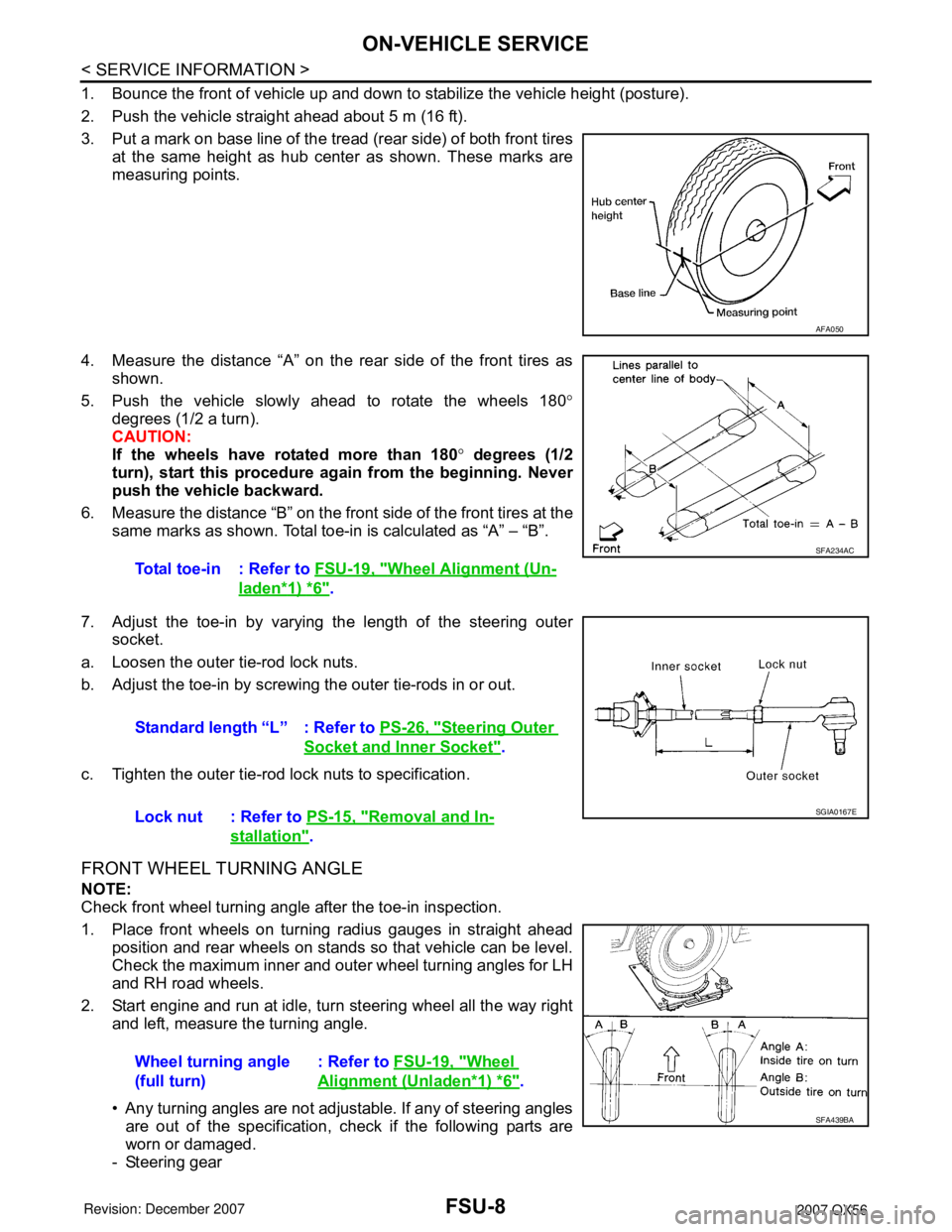
3. Put a mark on base line of the tread (rear side) of both front tires
at the same height as hub center as shown. These marks are
measuring points.
4. Measure the distance “A” on the rear side of the front tires as
shown.
5. Push the vehicle slowly ahead to rotate the wheels 180°
degrees (1/2 a turn).
CAUTION:
If the wheels have rotated more than 180° degrees (1/2
turn), start this procedure again from the beginning. Never
push the vehicle backward.
6. Measure the distance “B” on the front side of the front tires at the
same marks as shown. Total toe-in is calculated as “A” – “B”.
7. Adjust the toe-in by varying the length of the steering outer
socket.
a. Loosen the outer tie-rod lock nuts.
b. Adjust the toe-in by screwing the outer tie-rods in or out.
c. Tighten the outer tie-rod lock nuts to specification.
FRONT WHEEL TURNING ANGLE
NOTE:
Check front wheel turning angle after the toe-in inspection.
1. Place front wheels on turning radius gauges in straight ahead
position and rear wheels on stands so that vehicle can be level.
Check the maximum inner and outer wheel turning angles for LH
and RH road wheels.
2. Start engine and run at idle, turn steering wheel all the way right
and left, measure the turning angle.
• Any turning angles are not adjustable. If any of steering angles
are out of the specification, check if the following parts are
worn or damaged.
- Steering gear
AFA050
Total toe-in : Refer to FSU-19, "Wheel Alignment (Un-
laden*1) *6".
SFA234AC
Standard length “L” : Refer to PS-26, "Steering Outer
Socket and Inner Socket".
Lock nut : Refer to PS-15, "
Removal and In-
stallation".
SGIA0167E
Wheel turning angle
(full turn): Refer to FSU-19, "Wheel
Alignment (Unladen*1) *6".
SFA439BA
Page 1957 of 3061
COIL SPRING AND SHOCK ABSORBER
FSU-11
< SERVICE INFORMATION >
C
D
F
G
H
I
J
K
L
MA
B
FSU
N
O
P
INSPECTION AFTER DISASSEMBLY
Shock Absorber Assembly
• Check for smooth operation through a full stroke, both compression and extension.
• Check for oil leakage on welded or gland packing portions.
• Check piston rod for cracks, deformation or other damage and replace if necessary.
Mounting Insulator and Rubber Parts
Check cemented rubber-to-metal portion for separation or cracks. Check rubber parts for deterioration and
replace if necessary.
Coil Spring
• Check for cracks, deformation or other damage and replace if necessary.
• Check the free spring height.
ASSEMBLY
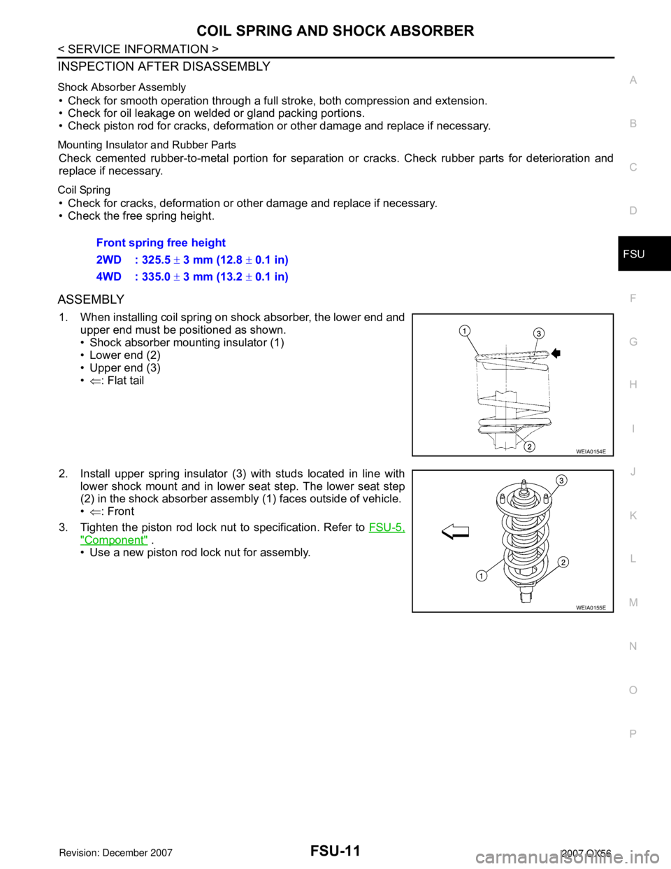
1. When installing coil spring on shock absorber, the lower end and
upper end must be positioned as shown.
• Shock absorber mounting insulator (1)
• Lower end (2)
• Upper end (3)
•⇐: Flat tail
2. Install upper spring insulator (3) with studs located in line with
lower shock mount and in lower seat step. The lower seat step
(2) in the shock absorber assembly (1) faces outside of vehicle.
•⇐: Front
3. Tighten the piston rod lock nut to specification. Refer to FSU-5,
"Component" .
• Use a new piston rod lock nut for assembly.Front spring free height
2WD : 325.5 ± 3 mm (12.8 ± 0.1 in)
4WD : 335.0 ± 3 mm (13.2 ± 0.1 in)
WEIA0154E
WEIA0155E
Page 1965 of 3061
SERVICE DATA AND SPECIFICATIONS (SDS)
FSU-19
< SERVICE INFORMATION >
C
D
F
G
H
I
J
K
L
MA
B
FSU
N
O
P
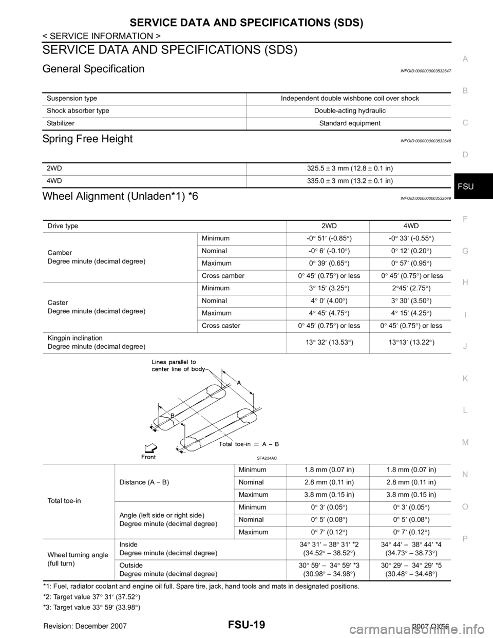
SERVICE DATA AND SPECIFICATIONS (SDS)
General SpecificationINFOID:0000000003532647
Spring Free HeightINFOID:0000000003532648
Wheel Alignment (Unladen*1) *6INFOID:0000000003532649
*1: Fuel, radiator coolant and engine oil full. Spare tire, jack, hand tools and mats in designated positions.
*2: Target value 37° 31′ (37.52°)
*3: Target value 33° 59′ (33.98°) Suspension type Independent double wishbone coil over shock
Shock absorber type Double-acting hydraulic
StabilizerStandard equipment
2WD325.5 ± 3 mm (12.8 ± 0.1 in)
4WD335.0 ± 3 mm (13.2 ± 0.1 in)
Drive type2WD 4WD
Camber
Degree minute (decimal degree)Minimum -0° 51′ (-0.85°)-0° 33′ (-0.55°)
Nominal -0° 6′ (-0.10°)0° 12′ (0.20°)
Maximum 0° 39′ (0.65°)0° 57′ (0.95°)
Cross camber 0° 45′ (0.75°) or less 0° 45′ (0.75°) or less
Caster
Degree minute (decimal degree)Minimum 3° 15′ (3.25°)2°45′ (2.75°)
Nominal 4° 0′ (4.00°)3° 30′ (3.50°)
Maximum 4° 45′ (4.75°)4° 15′ (4.25°)
Cross caster 0° 45′
(0.75°) or less 0° 45′ (0.75°) or less
Kingpin inclination
Degree minute (decimal degree)13° 32′ (13.53°)13°13′ (13.22°)
Total toe-inDistance (A − B)Minimum 1.8 mm (0.07 in) 1.8 mm (0.07 in)
Nominal 2.8 mm (0.11 in) 2.8 mm (0.11 in)
Maximum 3.8 mm (0.15 in) 3.8 mm (0.15 in)
Angle (left side or right side)
Degree minute (decimal degree)Minimum 0° 3′ (0.05°)0° 3′ (0.05°)
Nominal 0° 5′ (0.08°)0° 5′ (0.08°)
Maximum 0° 7′ (0.12°)0° 7′ (0.12°)
Wheel turning angle
(full turn)Inside
Degree minute (decimal degree)34° 31′ – 38° 31′ *2
(34.52° – 38.52°)34° 44′ – 38° 44′ *4
(34.73° – 38.73
°)
Outside
Degree minute (decimal degree)30° 59′ – 34° 59′ *3
(30.98° – 34.98°)30° 29′ – 34° 29′ *5
(30.48° – 34.48°)
SFA234AC
Page 1966 of 3061
FSU-20
< SERVICE INFORMATION >
SERVICE DATA AND SPECIFICATIONS (SDS)
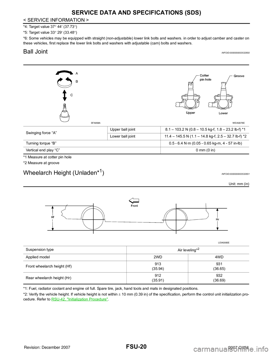
*4: Target value 37° 44′ (37.73°)
*5: Target value 33° 29′ (33.48°)
*6: Some vehicles may be equipped with straight (non-adjustable) lower link bolts and washers. in order to adjust camber and caster on
these vehicles, first replace the lower link bolts and washers with adjustable (cam) bolts and washers.
Ball JointINFOID:0000000003532650
*1 Measure at cotter pin hole
*2 Measure at groove
Wheelarch Height (Unladen*1)INFOID:0000000003532651
Unit: mm (in)
*1: Fuel, radiator coolant and engine oil full. Spare tire, jack, hand tools and mats in designated positions.
*2: Verify the vehicle height. If vehicle height is not within ± 10 mm (0.39 in) of the specification, perform the control unit initialization pro-
cedure. Refer to RSU-42, "
Initialization Procedure". Swinging force “A”Upper ball joint 8.1 – 103.2 N (0.8 – 10.5 kg-f, 1.8 – 23.2 lb-f) *1
Lower ball joint 11.4 – 145.5 N (1.1 – 14.8 kg-f, 2.5 – 32.7 lb-f) *2
Turning torque “B” 0.5 - 6.4 N·m (0.05 - 0.65 kg-m, 4 - 57 in-lb)
Vertical end play “C”0 mm (0 in)
SFA858AWEIA0076E
Suspension type
Air leveling*2
Applied model 2WD 4WD
Front wheelarch height (Hf)913
(35.94)931
(36.65)
Rear wheelarch height (Hr)912
(35.91)932
(36.69)
LEIA0085E