wiring diagram INFINITI QX56 2007 Factory Repair Manual
[x] Cancel search | Manufacturer: INFINITI, Model Year: 2007, Model line: QX56, Model: INFINITI QX56 2007Pages: 3061, PDF Size: 64.56 MB
Page 1091 of 3061

EC-8
DTC Confirmation Procedure ................................567
Wiring Diagram ......................................................569
Diagnosis Procedure .............................................570
Component Inspection ...........................................572
Removal and Installation .......................................573
DTC P2135 TP SENSOR .................................574
Component Description .........................................574
CONSULT-II Reference Value in Data Monitor
Mode ......................................................................
574
On Board Diagnosis Logic .....................................574
DTC Confirmation Procedure ................................574
Wiring Diagram ......................................................576
Diagnosis Procedure .............................................577
Component Inspection ...........................................579
Removal and Installation .......................................580
DTC P2138 APP SENSOR ..............................581
Component Description .........................................581
CONSULT-II Reference Value in Data Monitor
Mode ......................................................................
581
On Board Diagnosis Logic .....................................581
DTC Confirmation Procedure ................................582
Wiring Diagram ......................................................583
Diagnosis Procedure .............................................584
Component Inspection ...........................................587
Removal and Installation .......................................587
DTC P2A00, P2A03 A/F SENSOR 1 ...............588
Component Description .........................................588
CONSULT-II Reference Value in Data Monitor
Mode ......................................................................
588
On Board Diagnosis Logic .....................................588
DTC Confirmation Procedure ................................588
Wiring Diagram ......................................................590
Diagnosis Procedure .............................................593
Removal and Installation .......................................596
ASCD BRAKE SWITCH ..................................597
Component Description .........................................597
CONSULT-II Reference Value in Data Monitor
Mode ......................................................................
597
Wiring Diagram ......................................................598
Diagnosis Procedure .............................................599
Component Inspection ...........................................602
ASCD INDICATOR ..........................................603
Component Description .........................................603
CONSULT-II Reference Value in Data Monitor
Mode ......................................................................
603
Wiring Diagram ......................................................604
Diagnosis Procedure .............................................604
ELECTRICAL LOAD SIGNAL .........................606
Description .............................................................606
CONSULT-II Reference Value in Data Monitor
Mode ......................................................................
606
Diagnosis Procedure .............................................606
FUEL INJECTOR ..............................................608
Component Description ........................................608
CONSULT-II Reference Value in Data Monitor
Mode .....................................................................
608
Wiring Diagram .....................................................609
Diagnosis Procedure .............................................610
Component Inspection ..........................................612
Removal and Installation .......................................612
FUEL PUMP .....................................................613
Description ............................................................613
CONSULT-II Reference Value in Data Monitor
Mode .....................................................................
613
Wiring Diagram .....................................................614
Diagnosis Procedure .............................................615
Component Inspection ..........................................617
Removal and Installation .......................................618
ICC BRAKE SWITCH .......................................619
Component Description ........................................619
CONSULT-II Reference Value in Data Monitor
Mode .....................................................................
619
Wiring Diagram .....................................................620
Diagnosis Procedure .............................................621
Component Inspection ..........................................624
IGNITION SIGNAL ............................................626
Component Description ........................................626
Wiring Diagram .....................................................627
Diagnosis Procedure .............................................632
Component Inspection ..........................................635
Removal and Installation .......................................637
REFRIGERANT PRESSURE SENSOR ...........638
Component Description ........................................638
Wiring Diagram .....................................................639
Diagnosis Procedure .............................................640
Removal and Installation .......................................642
MIL AND DATA LINK CONNECTOR ...............643
Wiring Diagram .....................................................643
SERVICE DATA AND SPECIFICATIONS
(SDS) ................................................................
645
Fuel Pressure ........................................................645
Idle Speed and Ignition Timing .............................645
Calculated Load Value ..........................................645
Mass Air Flow Sensor ...........................................645
Intake Air Temperature Sensor .............................645
Engine Coolant Temperature Sensor ...................645
A/F Sensor 1 Heater .............................................645
Heated Oxygen sensor 2 Heater ..........................645
Crankshaft Position Sensor (POS) .......................646
Camshaft Position Sensor (PHASE) .....................646
Throttle Control Motor ...........................................646
Fuel Injector ..........................................................646
Fuel Pump .............................................................646
Page 1222 of 3061

POWER SUPPLY AND GROUND CIRCUIT
EC-139
< SERVICE INFORMATION >
C
D
E
F
G
H
I
J
K
L
MA
EC
N
P O
POWER SUPPLY AND GROUND CIRCUIT
Wiring DiagramINFOID:0000000003531636
Specification data are reference values and are measured between each terminal and ground.
CAUTION:
Do not use ECM ground terminals when measuring input/output voltage. Doing so may result in dam-
age to the ECM's transistor. Use a ground other than ECM terminals, such as the ground.
BBWA2088E
Page 1224 of 3061

POWER SUPPLY AND GROUND CIRCUIT
EC-141
< SERVICE INFORMATION >
C
D
E
F
G
H
I
J
K
L
MA
EC
N
P O
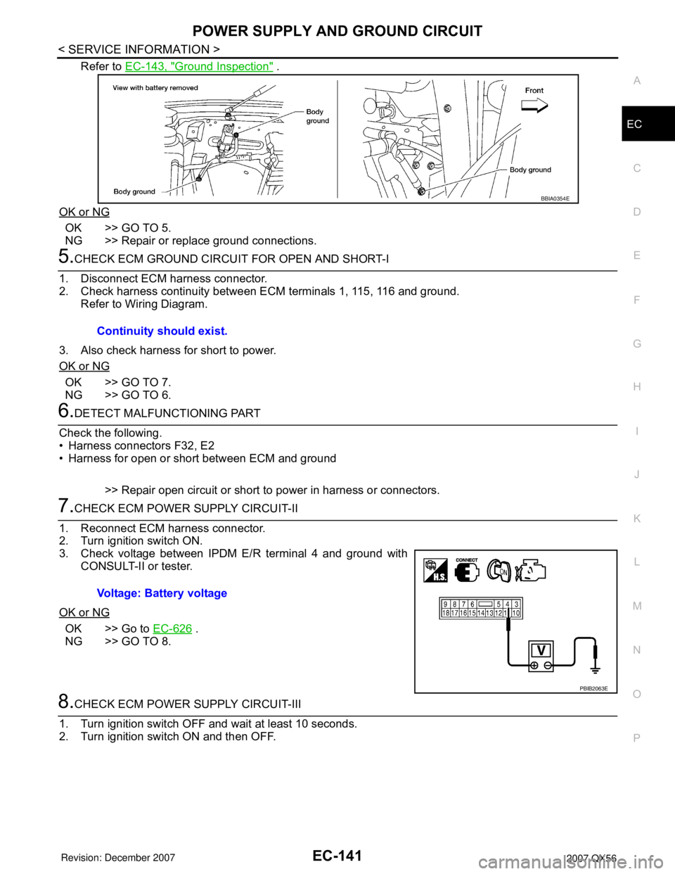
Refer to EC-143, "Ground Inspection" .
OK or NG
OK >> GO TO 5.
NG >> Repair or replace ground connections.
5.CHECK ECM GROUND CIRCUIT FOR OPEN AND SHORT-I
1. Disconnect ECM harness connector.
2. Check harness continuity between ECM terminals 1, 115, 116 and ground.
Refer to Wiring Diagram.
3. Also check harness for short to power.
OK or NG
OK >> GO TO 7.
NG >> GO TO 6.
6.DETECT MALFUNCTIONING PART
Check the following.
• Harness connectors F32, E2
• Harness for open or short between ECM and ground
>> Repair open circuit or short to power in harness or connectors.
7.CHECK ECM POWER SUPPLY CIRCUIT-II
1. Reconnect ECM harness connector.
2. Turn ignition switch ON.
3. Check voltage between IPDM E/R terminal 4 and ground with
CONSULT-II or tester.
OK or NG
OK >> Go to EC-626 .
NG >> GO TO 8.
8.CHECK ECM POWER SUPPLY CIRCUIT-III
1. Turn ignition switch OFF and wait at least 10 seconds.
2. Turn ignition switch ON and then OFF.
BBIA0354E
Continuity should exist.
Voltage: Battery voltage
PBIB2063E
Page 1225 of 3061

EC-142
< SERVICE INFORMATION >
POWER SUPPLY AND GROUND CIRCUIT
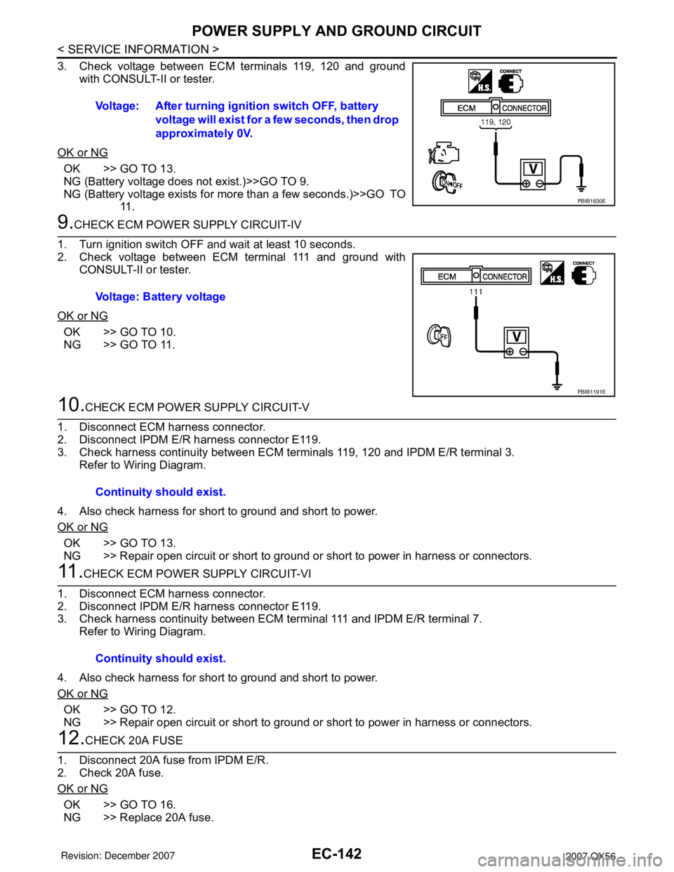
3. Check voltage between ECM terminals 119, 120 and ground
with CONSULT-II or tester.
OK or NG
OK >> GO TO 13.
NG (Battery voltage does not exist.)>>GO TO 9.
NG (Battery voltage exists for more than a few seconds.)>>GO TO
11 .
9.CHECK ECM POWER SUPPLY CIRCUIT-IV
1. Turn ignition switch OFF and wait at least 10 seconds.
2. Check voltage between ECM terminal 111 and ground with
CONSULT-II or tester.
OK or NG
OK >> GO TO 10.
NG >> GO TO 11.
10.CHECK ECM POWER SUPPLY CIRCUIT-V
1. Disconnect ECM harness connector.
2. Disconnect IPDM E/R harness connector E119.
3. Check harness continuity between ECM terminals 119, 120 and IPDM E/R terminal 3.
Refer to Wiring Diagram.
4. Also check harness for short to ground and short to power.
OK or NG
OK >> GO TO 13.
NG >> Repair open circuit or short to ground or short to power in harness or connectors.
11 .CHECK ECM POWER SUPPLY CIRCUIT-VI
1. Disconnect ECM harness connector.
2. Disconnect IPDM E/R harness connector E119.
3. Check harness continuity between ECM terminal 111 and IPDM E/R terminal 7.
Refer to Wiring Diagram.
4. Also check harness for short to ground and short to power.
OK or NG
OK >> GO TO 12.
NG >> Repair open circuit or short to ground or short to power in harness or connectors.
12.CHECK 20A FUSE
1. Disconnect 20A fuse from IPDM E/R.
2. Check 20A fuse.
OK or NG
OK >> GO TO 16.
NG >> Replace 20A fuse.Voltage: After turning ignition switch OFF, battery
voltage will exist for a few seconds, then drop
approximately 0V.
PBIB1630E
Voltage: Battery voltage
PBIB1191E
Continuity should exist.
Continuity should exist.
Page 1226 of 3061

POWER SUPPLY AND GROUND CIRCUIT
EC-143
< SERVICE INFORMATION >
C
D
E
F
G
H
I
J
K
L
MA
EC
N
P O
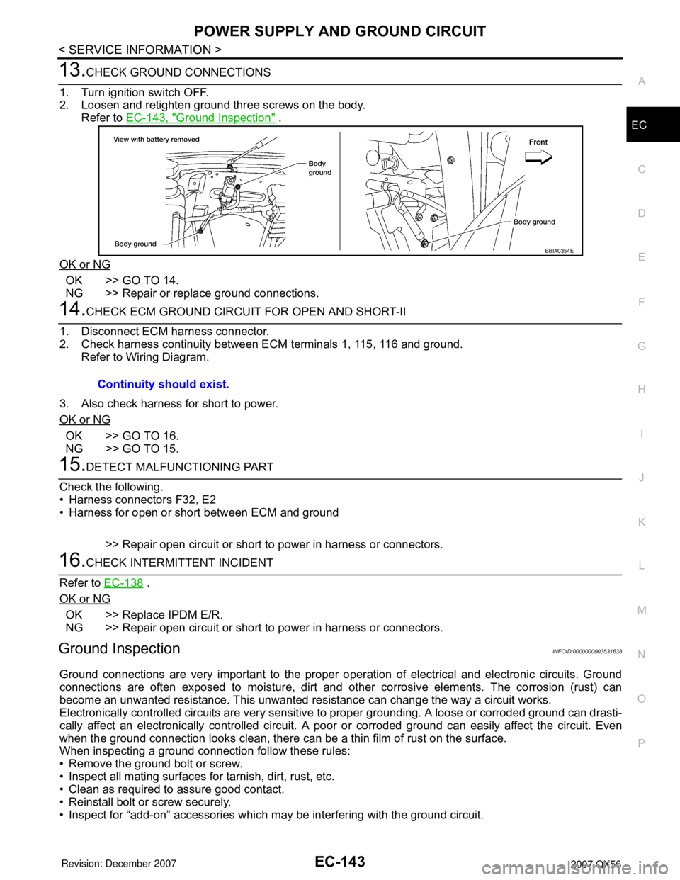
13.CHECK GROUND CONNECTIONS
1. Turn ignition switch OFF.
2. Loosen and retighten ground three screws on the body.
Refer to EC-143, "
Ground Inspection" .
OK or NG
OK >> GO TO 14.
NG >> Repair or replace ground connections.
14.CHECK ECM GROUND CIRCUIT FOR OPEN AND SHORT-II
1. Disconnect ECM harness connector.
2. Check harness continuity between ECM terminals 1, 115, 116 and ground.
Refer to Wiring Diagram.
3. Also check harness for short to power.
OK or NG
OK >> GO TO 16.
NG >> GO TO 15.
15.DETECT MALFUNCTIONING PART
Check the following.
• Harness connectors F32, E2
• Harness for open or short between ECM and ground
>> Repair open circuit or short to power in harness or connectors.
16.CHECK INTERMITTENT INCIDENT
Refer to EC-138
.
OK or NG
OK >> Replace IPDM E/R.
NG >> Repair open circuit or short to power in harness or connectors.
Ground InspectionINFOID:0000000003531638
Ground connections are very important to the proper operation of electrical and electronic circuits. Ground
connections are often exposed to moisture, dirt and other corrosive elements. The corrosion (rust) can
become an unwanted resistance. This unwanted resistance can change the way a circuit works.
Electronically controlled circuits are very sensitive to proper grounding. A loose or corroded ground can drasti-
cally affect an electronically controlled circuit. A poor or corroded ground can easily affect the circuit. Even
when the ground connection looks clean, there can be a thin film of rust on the surface.
When inspecting a ground connection follow these rules:
• Remove the ground bolt or screw.
• Inspect all mating surfaces for tarnish, dirt, rust, etc.
• Clean as required to assure good contact.
• Reinstall bolt or screw securely.
• Inspect for “add-on” accessories which may be interfering with the ground circuit.
BBIA0354E
Continuity should exist.
Page 1229 of 3061

EC-146
< SERVICE INFORMATION >
DTC U1000, U1001 CAN COMMUNICATION LINE
Wiring Diagram
INFOID:0000000003531642
Diagnosis ProcedureINFOID:0000000003531643
Go to LAN-44, "CAN System Specification Chart".
BBWA1671E
Page 1235 of 3061

EC-152
< SERVICE INFORMATION >
DTC P0011, P0021 IVT CONTROL
Wiring Diagram
INFOID:0000000003531652
BANK 1
Specification data are reference values and are measured between each terminal and ground.
Pulse signal is measured by CONSULT-II.
CAUTION:
BBWA2796E
Page 1240 of 3061

DTC P0011, P0021 IVT CONTROL
EC-157
< SERVICE INFORMATION >
C
D
E
F
G
H
I
J
K
L
MA
EC
N
P O
5.CHECK INTAKE VALVE TIMING CONTROL POSITION SENSOR GROUND CIRCUIT FOR OPEN AND
SHORT
1. Turn ignition switch OFF.
2. Check harness continuity between intake valve timing control position sensor terminal 1 and ground.
Refer to Wiring Diagram.
3. Also check harness for short to power.
OK or NG
OK >> GO TO 7.
NG >> GO TO 6.
6.DETECT MALFUNCTIONING PART
Check the following.
• Harness connectors E2, F32
• Harness for open or short between intake valve timing control position sensor and ground
>> Repair open circuit or short to power in harness or connectors.
7.CHECK INTAKE VALVE TIMING CONTROL POSITION SENSOR INPUT SIGNAL CIRCUIT FOR OPEN
AND SHORT
1. Disconnect ECM harness connector.
2. Check harness continuity between the following;
ECM terminal 72 and intake valve timing control position sensor (Bank 1) terminal 2 or
ECM terminal 53 and intake valve timing control position sensor (Bank 2) terminal 2.
Refer to Wiring Diagram.
3. Also check harness for short to ground and short to power.
OK or NG
OK >> GO TO 8.
NG >> Repair open circuit or short to ground or short to power in harness or connectors.
8.CHECK INTAKE VALVE TIMING CONTROL POSITION SENSOR
Refer to EC-159, "
Component Inspection".
OK or NG
OK >> GO TO 9.
NG >> Replace malfunctioning intake valve timing control position sensor. Refer to EC-160
.
9.CHECK INTAKE VALVE TIMING CONTROL SOLENOID VALVE POWER SUPPLY CIRCUIT
1. Reconnect ECM harness connector.
2. Disconnect intake valve timing control solenoid valve harness connector.Continuity should exist.
Continuity should exist.
Page 1241 of 3061

EC-158
< SERVICE INFORMATION >
DTC P0011, P0021 IVT CONTROL
3. Turn ignition switch ON.
4. Check voltage between intake valve timing control solenoid
valve terminal 2 and ground with CONSULT-II or tester.
OK or NG
OK >> GO TO 11.
NG >> GO TO 10.
10.DETECT MALFUNCTIONING PART
Check the following.
• Harness connectors E2, F32
• Harness for open or short between intake valve timing control solenoid valve and IPDM E/R.
>> Repair open circuit or short to ground or short to power in harness or connectors.
11 .CHECK INTAKE VALVE TIMING CONTROL SOLENOID VALVE OUTPUT SIGNAL CIRCUIT FOR OPEN
AND SHORT
1. Turn ignition switch OFF.
2. Disconnect ECM harness connector.
3. Check harness continuity between the following;
ECM terminal 10 and intake valve timing control solenoid valve (Bank 1) terminal 1 or
ECM terminal 11 and intake valve timing control solenoid valve (Bank 2) terminal 1.
Refer to Wiring Diagram.
4. Also check harness for short to ground and short to power.
OK or NG
OK >> GO TO 12.
NG >> Repair open circuit or short to ground or short to power in harness or connectors.
12.CHECK INTAKE VALVE TIMING CONTROL SOLENOID VALVE
1. Intake valve timing control position
sensor (bank 2)2. Intake valve timing control solenoid
valve (bank 2)3. Drive belt
4. Radiator hose 5. Intake valve timing control solenoid
valve (bank 1)6. Intake valve timing control position
sensor (bank 1)
Voltage: Battery voltage
BBIA0771E
PBIB0192E
Continuity should exist.
Page 1247 of 3061

EC-164
< SERVICE INFORMATION >
DTC P0031, P0032, P0051, P0052 A/F SENSOR 1 HEATER
WITH GST
Follow the procedure “WITH CONSULT-II” above.
Wiring DiagramINFOID:0000000003531660
BANK 1
Specification data are reference values and are measured between each terminal and ground.
BBWA2788E