valve body INFINITI QX56 2007 Factory Service Manual
[x] Cancel search | Manufacturer: INFINITI, Model Year: 2007, Model line: QX56, Model: INFINITI QX56 2007Pages: 3061, PDF Size: 64.56 MB
Page 79 of 3061
PRECAUTIONS
AT-9
< SERVICE INFORMATION >
D
E
F
G
H
I
J
K
L
MA
B
AT
N
O
P
•After performing each TROUBLE DIAGNOSIS, perform “DTC
(Diagnostic Trouble Code) CONFIRMATION PROCEDURE”.
If the repair is completed the DTC should not be displayed in
the “DTC CONFIRMATION PROCEDURE”.
• Always use the specified brand of ATF. Refer to MA-10
.
• Use paper rags not cloth rags during work.
• After replacing the ATF, dispose of the waste oil using the methods prescribed by law, ordinance, etc.
• Before proceeding with disassembly, thoroughly clean the outside of the transmission. It is important to pre-
vent the internal parts from becoming contaminated by dirt or other foreign matter.
• Disassembly should be done in a clean work area.
• Use lint-free cloth or towels for wiping parts clean. Common shop rags can leave fibers that could interfere
with the operation of the transmission.
• Place disassembled parts in order for easier and proper assembly.
• All parts should be carefully cleaned with a general purpose, non-flammable solvent before inspection or
reassembly.
• Gaskets, seals and O-rings should be replaced any time the transmission is disassembled.
• It is very important to perform functional tests whenever they are indicated.
• The valve body contains precision parts and requires extreme care when parts are removed and serviced.
Place disassembled valve body parts in order for easier and proper assembly. Care will also prevent springs
and small parts from becoming scattered or lost.
• Properly installed valves, sleeves, plugs, etc. will slide along bores in valve body under their own weight.
• Before assembly, apply a coat of recommended ATF to all parts. Apply petroleum jelly to protect O-rings and
seals, or hold bearings and washers in place during assembly. Do not use grease.
• Extreme care should be taken to avoid damage to O-rings, seals and gaskets when assembling.
• Clean or replace ATF cooler if excessive foreign material is found in oil pan or clogging strainer. Refer to AT-
15, "A/T Fluid Cooler Cleaning".
• After overhaul, refill the transmission with new ATF.
• When the A/T drain plug is removed, only some of the fluid is drained. Old A/T fluid will remain in torque con-
verter and ATF cooling system.
Always follow the procedures under “Changing A/T Fluid” in the AT section when changing A/T fluid. Refer to
AT-13, "
Changing Automatic Transmission Fluid (ATF)", AT-13, "Checking Automatic Transmission Fluid
(ATF)".
Service Notice or PrecautionINFOID:0000000003532221
ATF COOLER SERVICE
If A/T fluid contains frictional material (clutches, bands, etc.), or if an A/T is repaired, overhauled, or replaced,
inspect and clean the A/T fluid cooler mounted in the radiator or replace the radiator. Flush cooler lines using
cleaning solvent and compressed air after repair. For A/T fluid cooler cleaning procedure, refer to AT-15, "
A/T
Fluid Cooler Cleaning". For radiator replacement, refer to CO-13.
CHECKING AND CHANGING A/T FLUID SERVICE
Increase ATF temperature by 80°C (176°F) once, and then check ATF level in 65°C (149°F) when adjusting
ATF level.
NOTE:
JA60 uses both systems of a water-cooling and of an air-cooling. Air-cooling system has a by-pass valve.
When ATF temperature is not over 50°C (122°F) with water-cooling system OFF, it does not flow to air-cooling
system. If ATF level is set without the flow of ATF, the level will be 10mm lower than the standard. Therefore,
piping should be filled with ATF when adjusting level.
OBD-II SELF-DIAGNOSIS
• A/T self-diagnosis is performed by the TCM in combination with the ECM. Refer to the table on AT-83,
"CONSULT-II Function (A/T)" for the indicator used to display each self-diagnostic result.
SEF217U
Page 374 of 3061

ATC-4
< SERVICE INFORMATION >
PRECAUTIONS
not have dedicated recovery equipment, you may contact a local refrigerant product retailer for available ser-
vice. This refrigerant must be disposed of in acco rdance with all federal and local regulations. In addition,
replacement of all refrigerant system components on the vehicle is recommended.
• If the vehicle is within the warranty period, the air conditioner warranty is void. Please contact NISSAN Cus-
tomer Affairs for further assistance.
General Refrigerant PrecautionINFOID:0000000003533220
WARNING:
• Do not release refrigerant into th e air. Use approved recovery/recycling equipment to capture the
refrigerant every time an air conditioning system is discharged.
• Always wear eye and hand protection (goggles and gloves) when working with any refrigerant or air
conditioning system.
• Do not store or heat refrigerant containers above 52 °C (125 °F).
• Do not heat a refrigerant container with an open flame; if container warming is required, place the
bottom of the container in a warm pail of water.
• Do not intentionally drop, puncture, or incinerate refrigerant containers.
• Keep refrigerant away from open flames: poisonou s gas will be produced if refrigerant burns.
• Refrigerant will displace oxygen, therefore be certa in to work in well ventilated areas to prevent suf-
focation.
• Do not pressure test or leak test HFC-134a (R-134a) service equipment and/or vehicle air condition-
ing systems with compressed air during repair. Some mixtures of air and HFC-134a (R-134a) have
been shown to be combustible at elevated pressures. These mixtures, if ignited, may cause injury or
property damage. Additional heal th and safety information may be obtained from refrigerant manu-
facturers.
Precaution for Leak Detection DyeINFOID:0000000003533221
• The A/C system contains a fluorescent leak detection dye used for locating refrigerant leaks. An ultraviolet
(UV) lamp is required to illuminate the dye when inspecting for leaks.
• Always wear fluorescence enhancing UV safety goggles to protect your eyes and enhance the visibility of
the fluorescent dye.
• The fluorescent dye leak detector is not a replacement for an electronic refrigerant leak detector. The fluo-
rescent dye leak detector should be used in conjuncti on with an electronic refrigerant leak detector (J-
41995).
• For your safety and the customer's satisfaction, r ead and follow all manufacturer's operating instructions and
precautions prior to performing work.
• A compressor shaft seal should not be repaired because of dye seepage. The compressor shaft seal should only be repaired after confirming the leak with an electronic refrigerant leak detector (J-41995).
• Always remove any dye from the leak area after repairs are complete to avoid a misdiagnosis during a future
service.
• Do not allow dye to come into contact with painted body panels or interior components. If dye is spilled,
clean immediately with the approved dye cleaner. Fluoresc ent dye left on a surface for an extended period of
time cannot be removed .
• Do not spray the fluorescent dye cleaning agent on hot surfaces (engine exhaust manifold, etc.).
• Do not use more than one refrigerant dye bottle (1/4 ounce / 7.4 cc) per A/C system.
• Leak detection dyes for HFC-134a (R-134a) and CFC-12 (R -12) A/C systems are different. Do not use HFC-
134a (R-134a) leak detection dye in CFC-12 (R-12) A/ C systems or CFC-12 (R-12) leak detection dye in
HFC-134a (R-134a) A/C systems or A/C system damage may result.
• The fluorescent properties of the dye will remain for ov er three (3) years unless a compressor failure occurs.
A/C Identification LabelINFOID:0000000003533222
Vehicles with factory installed fluorescent dye have this identification label on the underside of hood.
Precaution for Refrigerant ConnectionINFOID:0000000003533223
A new type refrigerant connection has been introduced to al l refrigerant lines except the following locations.
• Expansion valve to cooling unit
• Evaporator pipes to evaporator (inside cooling unit)
• Refrigerant pressure sensor
FEATURES OF NEW TYPE REFRIGERANT CONNECTION
Page 504 of 3061
ATC-134
< SERVICE INFORMATION >
HEATER & COOLING UNIT ASSEMBLY
5. Disconnect the front heater hoses from the front heater core.
6. Disconnect the high/low pressure pipes from the front expansion valve.
7. Remove the instrument panel and console panel. Refer to IP-10, "
Removal and Installation".
8. Remove the steering column. Refer to PS-10
.
9. Disconnect the instrument panel wire harness at the RH and LH in-line connector brackets, and the fuse
block (J/B) electrical connectors. Refer to PG-3
.
10. Disconnect the steering member from each side of the vehicle body.
11. Remove the front heater and cooling unit assembly with it attached to the steering member, from the vehi-
cle.
CAUTION:
Use care not to damage the seats and interior tr im panels when removing the front heater and
cooling unit assembly with it at tached to the steering member.
12. Remove the front heater and cooling unit assembly from the steering member.
Installation
Installation is in the reverse order of removal.
CAUTION:
• Replace the O-ring of the low-pressure pipe and high-pressure pipe with a new one, and apply com-
pressor oil to it when installing it.
• After charging the refrigerant, check for leaks.
NOTE:
• Fill the engine cooling system with the s pecified coolant mixture. Refer to MA-12, "
Changing Engine Cool-
ant".
• Recharge the A/C system. Refer to ATC-150, "
HFC-134a (R-134a) Service Procedure".
REAR HEATER AND COOLING UNIT ASSEMBLY
Removal
1. Discharge the refrigerant from the A/C system. Refer to ATC-150, "HFC-134a (R-134a) Service Proce-
dure".
2. Drain the coolant from the engine cooling system. Refer to MA-12, "
Changing Engine Coolant".
3. Disconnect the rear heater core hoses from the rear heater core.
4. Disconnect the rear A/C pipes from the rear expansion valve.
5. Remove the luggage side finisher lower RH. Refer to EI-34
.
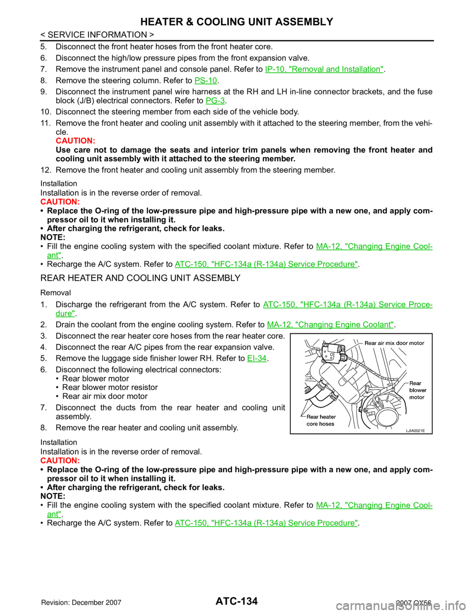
6. Disconnect the following electrical connectors: • Rear blower motor
• Rear blower motor resistor
• Rear air mix door motor
7. Disconnect the ducts from the rear heater and cooling unit assembly.
8. Remove the rear heater and cooling unit assembly.
Installation
Installation is in the reverse order of removal.
CAUTION:
• Replace the O-ring of the low-pressure pipe and high-pressure pipe with a new one, and apply com-
pressor oil to it when installing it.
• After charging the refrigerant, check for leaks.
NOTE:
• Fill the engine cooling system with the s pecified coolant mixture. Refer to MA-12, "
Changing Engine Cool-
ant".
• Recharge the A/C system. Refer to ATC-150, "
HFC-134a (R-134a) Service Procedure".
LJIA0021E
Page 906 of 3061

BR-8
< SERVICE INFORMATION >
BRAKE FLUID
BRAKE FLUID
On Board InspectionINFOID:0000000003532724
LEVEL CHECK
• Make sure the fluid level in reservoir tank is within the standard
(between MAX and MIN lines).
• Visually check around reservoir tank for fluid leaks.
• If fluid level is excessively low, check brake system for leaks.
• If brake warning lamp remains illuminated after parking lever is
released, check brake system for fluid leakage.
Drain and RefillINFOID:0000000003532725
CAUTION:
• Refill with new brake fluid. Refer to MA-10
.
• Do not reuse drained brake fluid.
• Do not let brake fluid splash on the painted surfaces of the body. This might damage the paint, so
when splashing it, immediately wipe off the area and wash away with water.
• Before servicing, disconnect actuator connector or battery negative cable.
1. Connect a vinyl tube to each bleed valve.
2. Depress brake pedal, loosen each bleed valve, and gradually
remove brake fluid.
3. Make sure there is no foreign material in reservoir tank, and refill
with new brake fluid.
4. Rest foot on brake pedal. Loosen bleed valve. Slowly depress
pedal until it stops. Tighten bleed valve. Release brake pedal.
Repeat this process a few times, then pause to add new brake
fluid to master cylinder. Continue until new brake fluid flows out.
Bleed air from brake system. Refer to BR-8, "
Bleeding Brake
System" .
Bleeding Brake SystemINFOID:0000000003532726
CAUTION:
While bleeding, pay attention to master cylinder fluid level.
1. Turn ignition switch OFF and disconnect ABS actuator and electric unit (control unit) connector or battery
negative cable.
2. Connect a vinyl tube to the rear right bleed valve.
3. Fully depress brake pedal 4 to 5 times.
LFIA0225E
SBR419C
SBR995
Page 916 of 3061
BR-18
< SERVICE INFORMATION >
FRONT DISC BRAKE
FRONT DISC BRAKE
On-vehicle InspectionINFOID:0000000003532738
PAD WEAR INSPECTION
• Inspect the thickness of pad through cylinder body inspection hole.
Use a scale for inspection if necessary. Refer to BR-30, "
Front Disc
Brake".
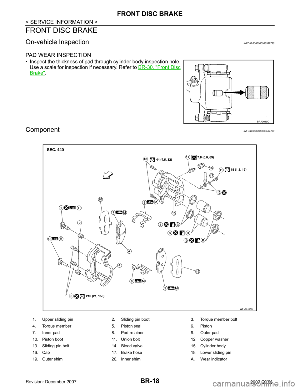
ComponentINFOID:0000000003532739
BRA0010D
1. Upper sliding pin 2. Sliding pin boot 3. Torque member bolt
4. Torque member 5. Piston seal 6. Piston
7. Inner pad 8. Pad retainer 9. Outer pad
10. Piston boot 11. Union bolt 12. Copper washer
13. Sliding pin bolt 14. Bleed valve 15. Cylinder body
16. Cap 17. Brake hose 18. Lower sliding pin
19. Outer shim 20. Inner shim A. Wear indicator
WFIA0451E
Page 922 of 3061

BR-24
< SERVICE INFORMATION >
REAR DISC BRAKE
REAR DISC BRAKE
On-vehicle InspectionINFOID:0000000003532743
PAD WEAR INSPECTION
• Inspect the thickness of pad through cylinder body inspection hole.
Use a scale for inspection if necessary.
Exploded ViewINFOID:0000000003532744
Standard thickness : 12.13 mm (0.478 in)
Repair limit thickness : 1.0 mm (0.039 in)
BRA0010D
1. Union bolt 2. Brake hose 3. Copper washer
4. Cap 5. Bleed valve 6. Bolt
7. Cylinder body 8. Piston seal 9. Piston
10. Piston boot 11. Knuckle slide 12. Sliding sleeve boot
13. Sliding sleeve 14. Inner pad 15. Outer pad
(B) : Brake fluid (R) : Rubber grease (M) : Molykote M-77
⇐: Front
WFIA0453E
Page 1000 of 3061
ENGINE COOLANT
CO-11
< SERVICE INFORMATION >
C
D
E
F
G
H
I
J
K
L
MA
CO
N
P O
3. Remove the vented reservoir cap and replace it with a non-vented reservoir cap before filling the cooling
system.
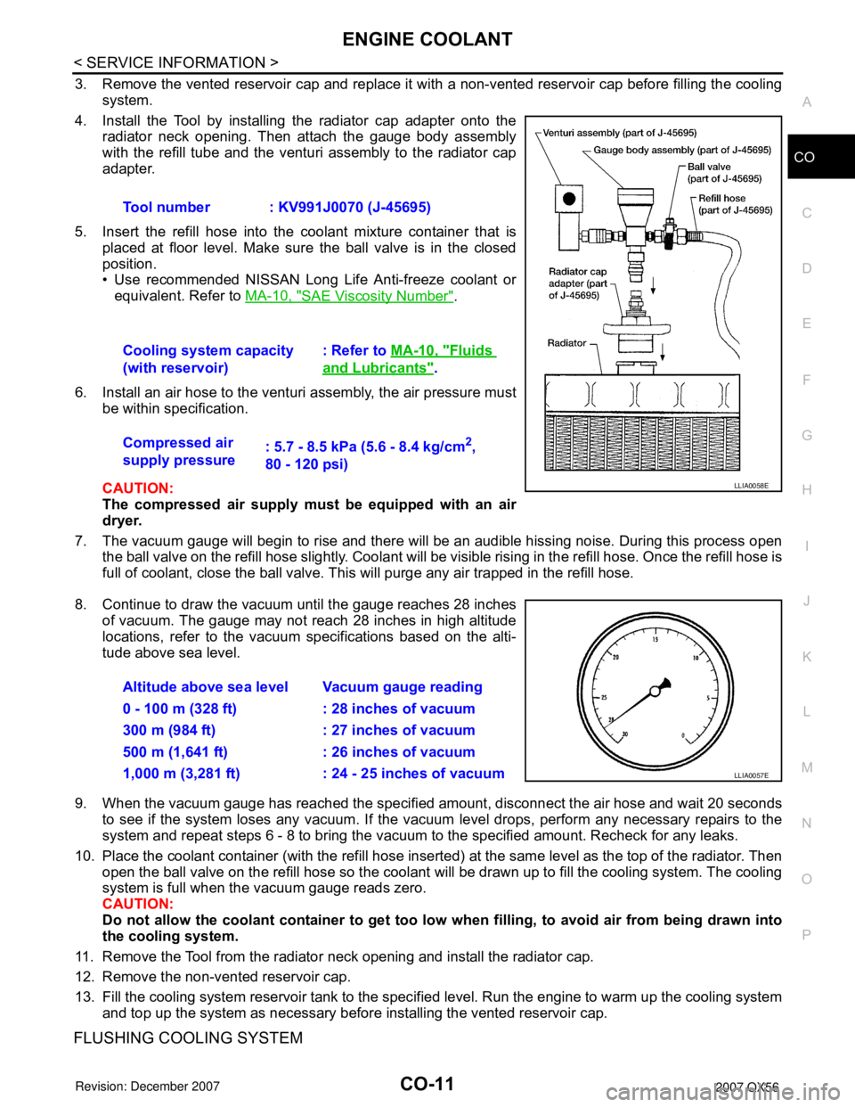
4. Install the Tool by installing the radiator cap adapter onto the
radiator neck opening. Then attach the gauge body assembly
with the refill tube and the venturi assembly to the radiator cap
adapter.
5. Insert the refill hose into the coolant mixture container that is
placed at floor level. Make sure the ball valve is in the closed
position.
• Use recommended NISSAN Long Life Anti-freeze coolant or
equivalent. Refer to MA-10, "
SAE Viscosity Number".
6. Install an air hose to the venturi assembly, the air pressure must
be within specification.
CAUTION:
The compressed air supply must be equipped with an air
dryer.
7. The vacuum gauge will begin to rise and there will be an audible hissing noise. During this process open
the ball valve on the refill hose slightly. Coolant will be visible rising in the refill hose. Once the refill hose is
full of coolant, close the ball valve. This will purge any air trapped in the refill hose.
8. Continue to draw the vacuum until the gauge reaches 28 inches
of vacuum. The gauge may not reach 28 inches in high altitude
locations, refer to the vacuum specifications based on the alti-
tude above sea level.
9. When the vacuum gauge has reached the specified amount, disconnect the air hose and wait 20 seconds
to see if the system loses any vacuum. If the vacuum level drops, perform any necessary repairs to the
system and repeat steps 6 - 8 to bring the vacuum to the specified amount. Recheck for any leaks.
10. Place the coolant container (with the refill hose inserted) at the same level as the top of the radiator. Then
open the ball valve on the refill hose so the coolant will be drawn up to fill the cooling system. The cooling
system is full when the vacuum gauge reads zero.
CAUTION:
Do not allow the coolant container to get too low when filling, to avoid air from being drawn into
the cooling system.
11. Remove the Tool from the radiator neck opening and install the radiator cap.
12. Remove the non-vented reservoir cap.
13. Fill the cooling system reservoir tank to the specified level. Run the engine to warm up the cooling system
and top up the system as necessary before installing the vented reservoir cap.
FLUSHING COOLING SYSTEM
Tool number : KV991J0070 (J-45695)
Cooling system capacity
(with reservoir): Refer to MA-10, "
Fluids
and Lubricants".
Compressed air
supply pressure: 5.7 - 8.5 kPa (5.6 - 8.4 kg/cm
2,
80 - 120 psi)
LLIA0058E
Altitude above sea level Vacuum gauge reading
0 - 100 m (328 ft) : 28 inches of vacuum
300 m (984 ft) : 27 inches of vacuum
500 m (1,641 ft) : 26 inches of vacuum
1,000 m (3,281 ft) : 24 - 25 inches of vacuum
LLIA0057E
Page 1194 of 3061

TROUBLE DIAGNOSIS
EC-111
< SERVICE INFORMATION >
C
D
E
F
G
H
I
J
K
L
MA
EC
N
P O
: Average voltage for pulse signal (Actual pulse signal can be confirmed by oscilloscope.)
*:Before measuring the terminal voltage, confirm that the battery is fully charged. Refer to SC-4
.
CONSULT-II Function (ENGINE)INFOID:0000000003531626
FUNCTION
108 BR/WICC brake switch
(Models with ICC system)
ASCD brake switch
(Models with ASCD system)[Ignition switch: ON]
• Brake pedal: Slightly depressedApproximately 0V
[Ignition switch: ON]
• Brake pedal: Fully releasedBATTERY VOLTAGE
(11 - 14V)
109 L/W Ignition switch[Ignition switch: OFF]0V
[Ignition switch: ON]BATTERY VOLTAGE
(11 - 14V)
111 W / BECM relay
(Self shut-off)[Engine is running]
[Ignition switch: OFF]
• For a few seconds after turning ignition
switch OFF0 - 1.5V
[Ignition switch: OFF]
• More than a few seconds after turning igni-
tion switch OFFBATTERY VOLTAGE
(11 - 14V)
11 3 G R F u e l p u m p r e l a y[Ignition switch: ON]
• For 1 second after turning ignition switch
ON
[Engine is running]0 - 1.5V
[Ignition switch: ON]
• More than 1 second after turning ignition
switch ONBATTERY VOLTAGE
(11 - 14V)
11 5
11 6B
B/WECM ground[Engine is running]
• Idle speedBody ground
11 7 L / YEVAP canister vent control
valve[Ignition switch: ON]BATTERY VOLTAGE
(11 - 14V)
11 9
120BR
BRPower supply for ECM[Ignition switch: ON]BATTERY VOLTAGE
(11 - 14V)
121 WPower supply for ECM
(Back-up)[Ignition switch: OFF]BATTERY VOLTAGE
(11 - 14V) TER-
MI-
NAL
NO.WIRE
COLORITEM CONDITION DATA (DC Voltage)
Diagnostic test mode Function
Work supportThis mode enables a technician to adjust some devices faster and more accurately by following the in-
dications on the CONSULT-II unit.
Self-diagnostic resultsSelf-diagnostic results such as 1st trip DTC, DTCs and 1st trip freeze frame data or freeze frame data
can be read and erased quickly.*
Data monitor Input/Output data in the ECM can be read.
Data monitor (SPEC)Input/Output of the specification for Basic fuel schedule, AFM, A/F feedback control value and the other
data monitor items can be read.
CAN diagnostic support mon-
itorThe results of transmit/receive diagnosis of CAN communication can be read.
Active testDiagnostic Test Mode in which CONSULT-II drives some actuators apart from the ECMs and also shifts
some parameters in a specified range.
DTC & SRT confirmation The status of system monitoring tests and the self-diagnosis status/result can be confirmed.
Function test This mode is used to inform customers when their vehicle condition requires periodic maintenance.
ECM part number ECM part number can be read.
Page 1238 of 3061

DTC P0011, P0021 IVT CONTROL
EC-155
< SERVICE INFORMATION >
C
D
E
F
G
H
I
J
K
L
MA
EC
N
P O
: Average voltage for pulse signal (Actual pulse signal can be confirmed by oscilloscope.)
Diagnosis ProcedureINFOID:0000000003531653
1.CHECK OIL PRESSURE WARNING LAMP
1. Start engine.
2. Check oil pressure warning lamp and confirm it is not illumi-
nated.
OK or NG
OK >> GO TO 2.
NG >> Go to LU-8, "
Inspection".
2.CHECK GROUND CONNECTIONS
1. Turn ignition switch OFF.
2. Loosen and retighten three ground screws on the body.
TER-
MI-
NAL
NO.WIRE
COLORITEM CONDITION DATA (DC Voltage)
11 L GIntake valve timing control
solenoid valve (Bank 2)[Engine is running]
•Warm-up condition
• Idle speedBATTERY VOLTAGE
(11 - 14V)
[Engine is running]
•Warm-up condition
• Engine speed: 2,000rpm7 - 12V
53 LIntake valve timing control
position sensor (Bank 2)[Engine is running]
•Warm-up condition
• Idle speed0 - 1.0V
[Engine is running]
• Engine speed: 2,000 rpm0 - 1.0V
111 W / BECM relay
(Self shut-off)[Engine is running]
[Ignition switch: OFF]
• For a few seconds after turning ignition
switch OFF0 - 1.5V
[Ignition switch: OFF]
• More than a few seconds after turning igni-
tion switch OFFBATTERY VOLTAGE
(11 - 14V)
11 9
120BR
BRPower supply for ECM[Ignition switch: ON]BATTERY VOLTAGE
(11 - 14V)
PBIB1790E
PBIB2046E
PBIA8559J
Page 1544 of 3061

DTC P1140, P1145 IVT CONTROL POSITION SENSOR
EC-461
< SERVICE INFORMATION >
C
D
E
F
G
H
I
J
K
L
MA
EC
N
P O
: Average voltage for pulse signal (Actual pulse signal can be confirmed by oscilloscope.)
Diagnosis ProcedureINFOID:0000000003531977
1.CHECK GROUND CONNECTIONS
1. Turn ignition switch OFF.
2. Loosen and retighten three ground screws on the body.
Refer to EC-143, "
Ground Inspection".
OK or NG
OK >> GO TO 2.
NG >> Repair or replace ground connections.
2.CHECK INTAKE VALVE TIMING CONTROL POSITION SENSOR POWER SUPPLY CIRCUIT
1. Disconnect intake valve timing control position sensor harness connector.
TER-
MI-
NAL
NO.WIRE
COLORITEM CONDITION DATA (DC Voltage)
53 LIntake valve timing control
position sensor (Bank 2)[Engine is running]
•Warm-up condition
• Idle speed0 - 1.0V
[Engine is running]
• Engine speed: 2,000 rpm0 - 1.0V
111 W / BECM relay
(Self shut-off)[Engine is running]
[Ignition switch: OFF]
• For a few seconds after turning ignition
switch OFF0 - 1.5V
[Ignition switch: OFF]
• More than a few seconds after turning igni-
tion switch OFFBATTERY VOLTAGE
(11 - 14V)
11 9
120BR
BRPower supply for ECM[Ignition switch: ON]BATTERY VOLTAGE
(11 - 14V)
PBIB2046E
BBIA0354E