Cooling INFINITI QX56 2011 Factory Service Manual
[x] Cancel search | Manufacturer: INFINITI, Model Year: 2011, Model line: QX56, Model: INFINITI QX56 2011Pages: 5598, PDF Size: 94.53 MB
Page 1 of 5598

A
B
D
E
F
G
H
I
J
K
L
M
N
P
O
C
QUICK REFERENCE INDEX
AGENERAL INFORMATIONGIGeneral Information
BENGINEEMEngine Mechanical
LUEngine Lubrication System
COEngine Cooling System
ECEngine Control System
FLFuel System
EXExhaust System
STRStarting System
ACCAccelerator Control System
CHYBRIDHBCHybrid Control System
HBBHybrid Battery System
HBRHybrid Brake System
DTRANSMISSION & DRIVE-
LINECLClutch
TMTransaxle & Transmission
DLNDriveline
FAXFront Axle
RAXRear Axle
ESUSPENSIONFSUFront Suspension
RSURear Suspension
SCSSuspension Control System
WTRoad Wheels & Tires
FBRAKESBRBrake System
PBParking Brake System
BRCBrake Control System
GSTEERINGSTSteering System
STCSteering Control System
HRESTRAINTSSBSeat Belt
SBCSeat Belt Control System
SRSRS Airbag
SRCSRS Airbag Control System
IVENTILATION, HEATER &
AIR CONDITIONERVTLVentilation System
HAHeater & Air Conditioning System
HACHeater & Air Conditioning Control System
JBODY INTERIORINTInterior
IPInstrument Panel
SESeat
ADPAutomatic Drive Positioner
KBODY EXTERIOR,
DOORS, ROOF & VEHICLE
SECURITYDLKDoor & Lock
SECSecurity Control System
GWGlass & Window System
PWCPower Window Control System
RFRoof
HDHood
EXTExterior
BRMBody Repair
LDRIVER CONTROLSMIRMirrors
EXLExterior Lighting System
INLInterior Lighting System
WWWiper & Washer
DEFDefogger
HRNHorn
MELECTRICAL & POWER
CONTROLPWOPower Outlet
BCSBody Control System
LANLAN System
PCSPower Control System
CHGCharging System
PGPower Supply, Ground & Circuit Elements
NDRIVER INFORMATION &
MULTIMEDIAMWIMeter, Warning Lamp & Indicator
WCSWarning Chime System
SNSonar System
AVAudio, Visual & Navigation System
OCRUISE CONTROL &
DRIVER ASSISTANCECCSCruise Control System
DASDriver Assistance System
DMSDrive Mode System
PMAINTENANCEMAMaintenance
All rights reserved. No part
of this Service Manual may
be reproduced or stored in a
retrieval system, or transmit-
ted in any form, or by any
means, electronic, mechani-
cal, recording or otherwise,
without the prior written per-
mission of NISSAN MOTOR
CO., LTD.
Edition: May 2010
Publication No. SM1E-1Z62U0
Page 3 of 5598

QUICK REFERENCE CHART QX56
QUICK REFERENCE CHART QX56PFP:00000
ENGINE TUNE-UP DATA (VK56VD)ELS0003W
Engine modelVK56VD
Firing order 1-8-7-3-6-5-4-2
Idle speed
A/T (In “P or N” position) rpm
600 ± 50
Ignition timing
(BTDC at idle speed) 12
° ± 2 °
CO% at idle 0.7 - 9.9 % and engine runs smoothly
Tensions of drive belt Auto adjustment by auto tensioner
Radiater cap relief pressure kPa (kg/cm
2 , psi)
Standard 108.2 - 127.8 (1.1 - 1.3, 15.7 - 18.5)
Limit 98 (1.0, 14)
Cooling system leakage testing pressure kPa (kg/cm
2 , psi)186 (1.9, 27)
Compression pressure kPa (kg/cm
2 , psi)/rpm
Standard 1,667 (17, 242)/200
Minimum 1,226 (12.5, 178)/200
Differential limit between cylinders 98 (1.0, 14)/200
Spark plug
(Iridium-tipped type) Make NGK
Standard type DILKAR7B11
Gap (Standard) mm (in) 1.1 (0.043)
2011
Page 847 of 5598
![INFINITI QX56 2011 Factory Service Manual
CCS-112
< DTC/CIRCUIT DIAGNOSIS >[ICC]
C1A21 UNIT HIGH TEMP
ICC SENSOR : Diagnosis Procedure
INFOID:0000000006224344
1.CHECK ENGINE COOLING SYSTEM
Check for any malfunctions in engine cooling system. INFINITI QX56 2011 Factory Service Manual
CCS-112
< DTC/CIRCUIT DIAGNOSIS >[ICC]
C1A21 UNIT HIGH TEMP
ICC SENSOR : Diagnosis Procedure
INFOID:0000000006224344
1.CHECK ENGINE COOLING SYSTEM
Check for any malfunctions in engine cooling system.](/img/42/57033/w960_57033-846.png)
CCS-112
< DTC/CIRCUIT DIAGNOSIS >[ICC]
C1A21 UNIT HIGH TEMP
ICC SENSOR : Diagnosis Procedure
INFOID:0000000006224344
1.CHECK ENGINE COOLING SYSTEM
Check for any malfunctions in engine cooling system.
Is engine cooling system normal?
YES >> Replace the ICC sensor. Refer to CCS-176, "Exploded View".
NO >> Repair engine cooling system.
Revision: 2010 May2011 QX56
Page 943 of 5598

CO-1
ENGINE
C
DE
F
G H
I
J
K L
M
SECTION CO
A
CO
N
O P
CONTENTS
ENGINE COOLING SYSTEM
PRECAUTION ................ ...............................2
PRECAUTIONS .............................................. .....2
Precaution for Supplemental Restraint System
(SRS) "AIR BAG" and "SEAT BELT PRE-TEN-
SIONER" ............................................................. ......
2
PREPARATION ............................................3
PREPARATION .............................................. .....3
Commercial Service Tools ................................. ......3
SYSTEM DESCRIPTION ..............................4
DESCRIPTION ............................................... .....4
Engine Cooling System ..................................... ......4
Engine Cooling System Schematic .........................5
SYMPTOM DIAGNOSIS ...............................6
OVERHEATING CAUSE ANALYSIS ............. .....6
Troubleshooting Chart ........................................ ......6
PERIODIC MAINTENANCE ..........................8
ENGINE COOLANT ....................................... .....8
Inspection ............................................................ ......8
Draining .....................................................................8
Refilling .....................................................................9
Flushing ...................................................................10
RADIATOR .........................................................11
RESERVOIR TANK CAP ..........................................11
RESERVOIR TANK CAP : Inspection ................. ....11
RADIATOR ............................................................. ....11
RADIATOR : Inspection ...........................................11
REMOVAL AND INSTALLATION ...............13
RADIATOR ....................................... .................13
Exploded View ..................................................... ....13
Removal and Installation .........................................13
Inspection ................................................................15
COOLING FAN ..................................................16
Exploded View .........................................................16
Removal and Installation .........................................16
Inspection ................................................................17
WATER PUMP ..................................................18
Exploded View .........................................................18
Removal and Installation .........................................18
Inspection ................................................................19
WATER INLET AND THERMOSTAT ASSEM-
BLY ....................................................................
20
Exploded View .........................................................20
Removal and Installation .........................................20
Inspection ................................................................21
SERVICE DATA AND SPECIFICATIONS
(SDS) ............... .............................................
23
SERVICE DATA AND SPECIFICATIONS
(SDS) .................................................................
23
Periodical Maintenance Specification ................ ....23
Radiator ...................................................................23
Thermostat ..............................................................23
Revision: 2010 May2011 QX56
Page 946 of 5598

CO-4
< SYSTEM DESCRIPTION >
DESCRIPTION
SYSTEM DESCRIPTION
DESCRIPTION
Engine Cooling SystemINFOID:0000000006289654
JPBIA4247GB
Revision: 2010 May2011 QX56
Page 947 of 5598

DESCRIPTIONCO-5
< SYSTEM DESCRIPTION >
C
DE
F
G H
I
J
K L
M A
CO
NP
O
Engine Cooling System SchematicINFOID:0000000006289655
JPBIA4248GB
Revision: 2010 May2011 QX56
Page 948 of 5598

CO-6
< SYMPTOM DIAGNOSIS >
OVERHEATING CAUSE ANALYSIS
SYMPTOM DIAGNOSIS
OVERHEATING CAUSE ANALYSIS
Troubleshooting ChartINFOID:0000000006289656
Symptom Check items
Cooling sys-
tem parts
malfunction Poor heat transfer
Water pump malfunction Worn or loose drive belt
—
Thermostat stuck closed —
Damaged fins
Dust contamination or pa-
per clogging
Physical damage
Clogged radiator cooling
tube Excess foreign material
(rust, dirt, sand, etc.)
Reduced air flow Cooling fan does not oper-
ate
Fan assembly —
High resistance to fan rota-
tion
Damaged fan blades
Damaged radiator shroud — — —
Improper engine coolant
mixture ratio ———
Poor engine coolant quality — Engine coolant density —
Insufficient engine coolant Engine coolant leakageCooling hose
Loose clamp
Cracked hose
Water pump Poor sealing
Radiator cap Loose
Poor sealing
Radiator O-ring for da
mage, deterio-
ration or improper fitting
Cracked radiator tank
Cracked radiator core
Reservoir tank Cracked reservoir tank
Overflowing reservoir tank Exhaust gas leakage into
cooling system Cylinder head deterioration
Cylinder head gasket deteri-
oration
Revision: 2010 May2011 QX56
Page 950 of 5598

CO-8
< PERIODIC MAINTENANCE >
ENGINE COOLANT
PERIODIC MAINTENANCE
ENGINE COOLANT
InspectionINFOID:0000000006289657
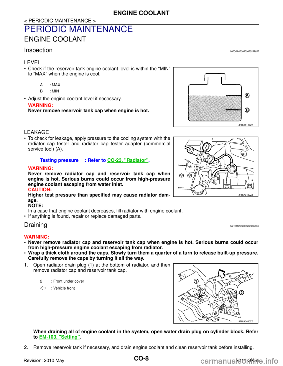
LEVEL
Check if the reservoir tank engine coolant level is within the “MIN”to “MAX” when the engine is cool.
Adjust the engine coolant level if necessary. WARNING:
Never remove reservoir tank cap when engine is hot.
LEAKAGE
To check for leakage, apply pressure to the cooling system with theradiator cap tester and radiator cap tester adapter (commercial
service tool) (A).
WARNING:
Never remove radiator cap and reservoir tank cap when
engine is hot. Serious burns could occur from high-pressure
engine coolant escaping from water inlet.
CAUTION:
Higher test pressure than specified may cause radiator dam-
age.
NOTE:
In a case that engine coolant decreas es, fill radiator with engine coolant.
If anything is found, repair or replace damaged parts.
DrainingINFOID:0000000006289658
WARNING:
Never remove radiator cap and reservoir tank cap when engine is hot. Serious burns could occur
from high-pressure engine co olant escaping from radiator.
Wrap a thick cloth around the caps. Slowly turn them a quarter of a turn to release built-up pressure.
Carefully remove the caps by turning it all the way.
1. Open radiator drain plug (1) at the bottom of radiator, and then remove radiator cap and reservoir tank cap.
When draining all of engine cool ant in the system, open water drai n plug on cylinder block. Refer
to EM-103, "
Setting".
2. Remove reservoir tank if necessary, and drain engine coolant and clean reservoir tank before installing.
A: MAX
B: MIN
JPBIA0102ZZ
Testing pressure : Refer to CO-23, "Radiator".
JPBIA3432ZZ
2 : Front under cover
: Vehicle front
JPBIA3430ZZ
Revision: 2010 May2011 QX56
Page 951 of 5598

ENGINE COOLANTCO-9
< PERIODIC MAINTENANCE >
C
DE
F
G H
I
J
K L
M A
CO
NP
O
3. Check drained engine coolant for contaminants such as rust, corrosion or discoloration.
If contaminated, flush the engine cooling system. Refer to CO-10, "
Flushing".
RefillingINFOID:0000000006289659
1. Install reservoir tank if removed, and radiator drain plug.
CAUTION:
Be sure to clean drain plug and install with new O-ring. Refer to CO-13, "
Exploded View".
If water drain plug on cylinder block is removed, close and tighten it. Refer to EM-107, "
Disassem-
bly and Assembly".
2. Check that each hose clamp is firmly tightened.
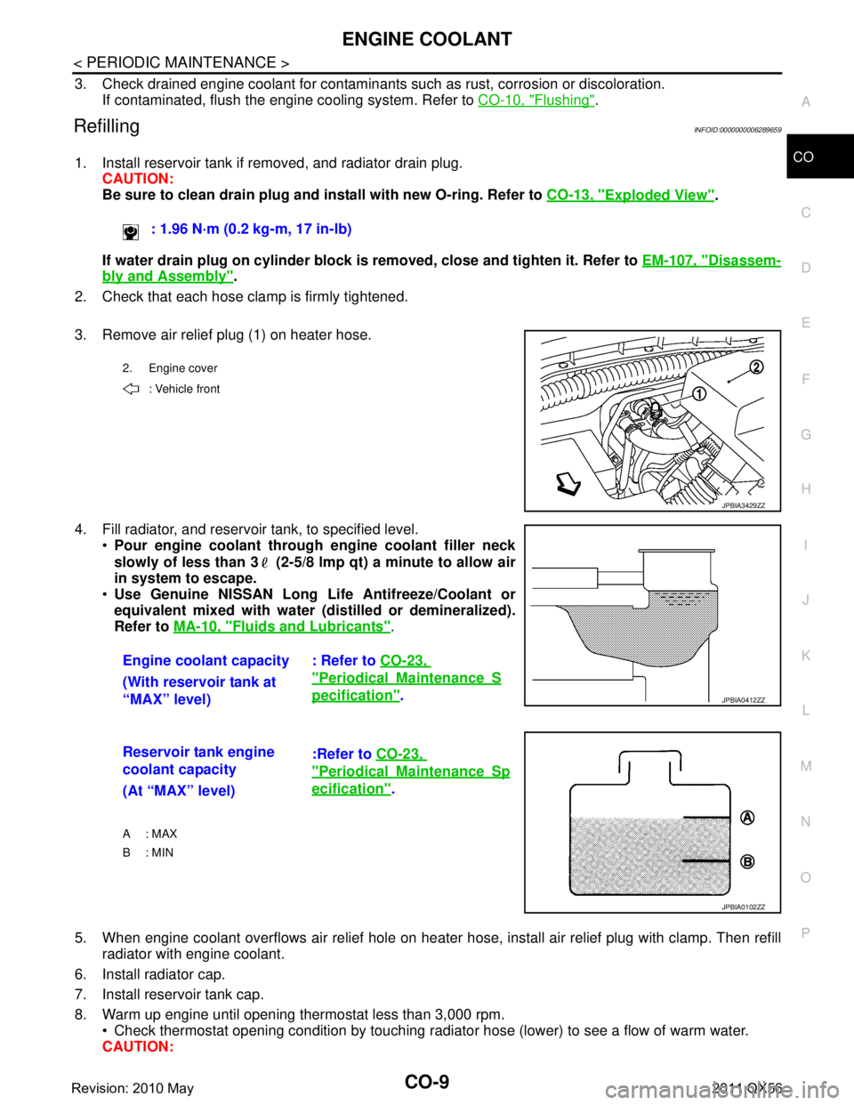
3. Remove air relief plug (1) on heater hose.
4. Fill radiator, and reservoir tank, to specified level. Pour engine coolant through engine coolant filler neck
slowly of less than 3 (2-5/8 lmp qt) a minute to allow air
in system to escape.
Use Genuine NISSAN Long Li fe Antifreeze/Coolant or
equivalent mixed with water (dis tilled or demineralized).
Refer to MA-10, "
Fluids and Lubricants".
5. When engine coolant overflows air relief hole on heater hos e, install air relief plug with clamp. Then refill
radiator with engine coolant.
6. Install radiator cap.
7. Install reservoir tank cap.
8. Warm up engine until opening thermostat less than 3,000 rpm. Check thermostat opening condition by touching radiat or hose (lower) to see a flow of warm water.
CAUTION: : 1.96 N·m (0.2 kg-m, 17 in-lb)
2. Engine cover
: Vehicle front
JPBIA3429ZZ
Engine coolant capacity : Refer to CO-23,
"PeriodicalMaintenanceS
pecification".
(With reservoir tank at
“MAX” level)JPBIA0412ZZ
Reservoir tank engine
coolant capacity :Refer to
CO-23,
"PeriodicalMaintenanceSp
ecification".
(At “MAX” level)
A : MAX
B: MIN
JPBIA0102ZZ
Revision: 2010 May2011 QX56
Page 952 of 5598

CO-10
< PERIODIC MAINTENANCE >
ENGINE COOLANT
Watch water temperature gauge so as not to overheat engine.
9. Stop the engine and cool down to less than approximately 50 °C (122 °F).
Cool down using fan to reduce the time.
If necessary, refill radiator up to filler neck with engine coolant.
10. Refill reservoir tank to “MAX” level line with engine coolant if necessary.
11. Repeat steps 6 through 10 two or more times with reservoir tank cap installed until engine coolant level no longer drops.
12. Check cooling system for leakage with engine running.
13. Warm up the engine, and check for sound of engine coolant flow while running engine from idle up to 3,000 rpm with heater temperature controller set at several position between “COOL” and “WARM”.
Sound may be noticeable at heater unit.
14. Repeat step 13 three times.
15. If sound is heard, bleed air from cooling system by repeating step 4, and steps from 6 to 14 until engine
coolant level no longer drops.
FlushingINFOID:0000000006289660
1. Install reservoir tank if removed, and radiator drain plug. CAUTION:
Be sure to clean drain plug and install with new O-ring. Refer to CO-13, "
Exploded View".
If water drain plug on cylinder block is removed, close and tighten it. Refer to EM-107, "
Disassem-
bly and Assembly".
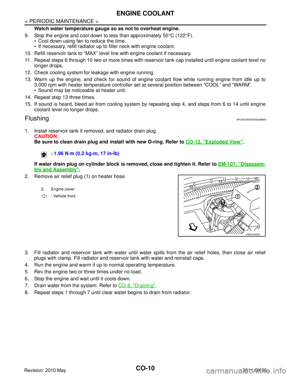
2. Remove air relief plug (1) on heater hose.
3. Fill radiator and reservoir tank with water until water spills from the air relief holes, then close air relief
plugs with clamp. Fill radiator and reservoir tank with water and reinstall caps.
4. Run the engine and warm it up to normal operating temperature.
5. Rev the engine two or three times under no-load.
6. Stop the engine and wait until it cools down.
7. Drain water from the system. Refer to CO-8, "
Draining".
8. Repeat steps 1 through 7 until clear water begins to drain from radiator. : 1.96 N·m (0.2 kg-m, 17 in-lb)
2. Engine cover
: Vehicle front
JPBIA3429ZZ
Revision: 2010 May2011 QX56