Cooling INFINITI QX56 2011 Factory User Guide
[x] Cancel search | Manufacturer: INFINITI, Model Year: 2011, Model line: QX56, Model: INFINITI QX56 2011Pages: 5598, PDF Size: 94.53 MB
Page 953 of 5598
RADIATORCO-11
< PERIODIC MAINTENANCE >
C
DE
F
G H
I
J
K L
M A
CO
NP
O
RADIATOR
RESERVOIR TANK CAP
RESERVOIR TANK CAP : InspectionINFOID:0000000006289661
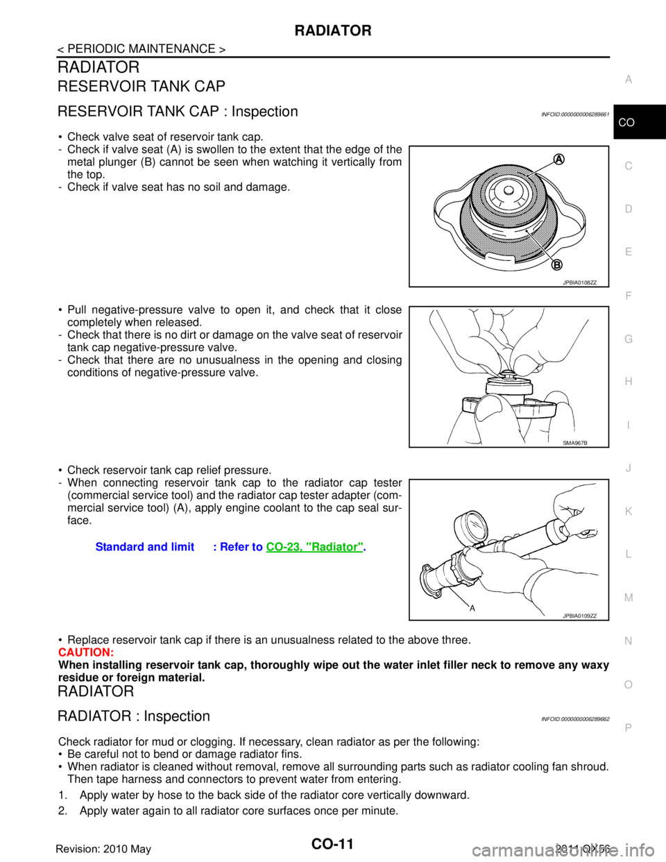
Check valve seat of reservoir tank cap.
- Check if valve seat (A) is swollen to the extent that the edge of the
metal plunger (B) cannot be seen when watching it vertically from
the top.
- Check if valve seat has no soil and damage.
Pull negative-pressure valve to open it, and check that it close completely when released.
- Check that there is no dirt or dam age on the valve seat of reservoir
tank cap negative-pressure valve.
- Check that there are no unusualness in the opening and closing conditions of negative-pressure valve.
Check reservoir tank cap relief pressure.
- When connecting reservoir tank cap to the radiator cap tester (commercial service tool) and the r adiator cap tester adapter (com-
mercial service tool) (A), apply engine coolant to the cap seal sur-
face.
Replace reservoir tank cap if there is an unusualness related to the above three.
CAUTION:
When installing reservoir tank cap , thoroughly wipe out the water inlet filler neck to remove any waxy
residue or foreign material.
RADIATOR
RADIATOR : InspectionINFOID:0000000006289662
Check radiator for mud or clogging. If neces sary, clean radiator as per the following:
Be careful not to bend or damage radiator fins.
When radiator is cleaned without removal, remove all surrounding parts such as radiator cooling fan shroud. Then tape harness and connectors to prevent water from entering.
1. Apply water by hose to the back side of the radiator core vertically downward.
2. Apply water again to all radiator core surfaces once per minute.
JPBIA0108ZZ
SMA967B
Standard and limit : Refer to CO-23, "Radiator".
JPBIA0109ZZ
Revision: 2010 May2011 QX56
Page 956 of 5598
CO-14
< REMOVAL AND INSTALLATION >
RADIATOR
to release built-up pressure. Carefully remove radiator cap by turning it all the way. Note that the reser-
voir tank cap side is also under pressure.
1. Remove front under cover with power tool. Refer to EXT-25, "
Exploded View".
2. Remove engine cover. Refer to EM-25, "
Exploded View".
3. Drain engine coolant from radiator. Refer to CO-8, "
Draining".
CAUTION:
Perform this step when the engine is cold.
Never spill engine coolant on drive belts.
4. Remove radiator hose (lower).
5. Remove fan shroud (lower). Refer to CO-13, "
Exploded View".
6. Move reservoir tank to the position without the hindrance for work.
7. Remove radiator core support cover. Refer to DLK-220, "
Exploded View".
8. Remove fan shroud (upper), refer to following.
a. Remove EVAP hose mounting bolts and move harness to aside.
b. Move air cleaner case to the position without the hindrance for work. Refer to EM-27, "
Exploded View".
NOTE:
The air cleaner case connector is not required to be disconnected.
9. Remove radiator grille. Refer to EXT-19, "
Exploded View".
10. Move condenser to the position without the hindranc e for work with the following procedures. Refer to HA-
38, "Exploded View".
Remove mounting bolts and disconnect A/C piping from radiator.
Remove air guide from radiator. Refer to EXT-12, "
Exploded View".
Remove radiator mounting bolts.
11. Remove radiator hose (upper).
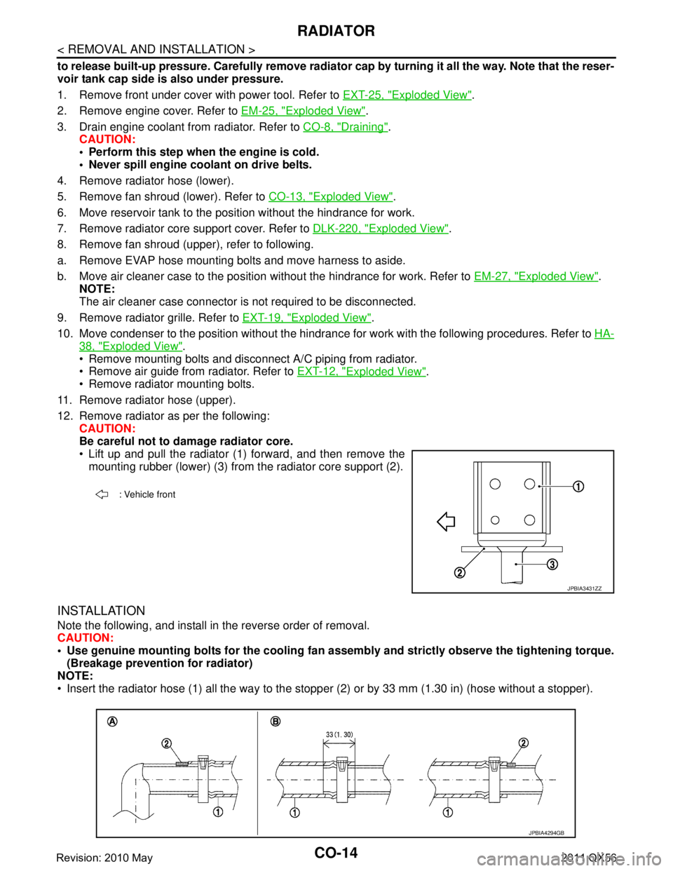
12. Remove radiator as per the following: CAUTION:
Be careful not to damage radiator core.
Lift up and pull the radiator (1) forward, and then remove themounting rubber (lower) (3) from the radiator core support (2).
INSTALLATION
Note the following, and install in the reverse order of removal.
CAUTION:
Use genuine mounting bolts for th e cooling fan assembly and strictly observe the tightening torque.
(Breakage prevention for radiator)
NOTE:
Insert the radiator hose (1) all the way to the st opper (2) or by 33 mm (1.30 in) (hose without a stopper).
: Vehicle front
JPBIA3431ZZ
JPBIA4294GB
Revision: 2010 May2011 QX56
Page 958 of 5598
CO-16
< REMOVAL AND INSTALLATION >
COOLING FAN
COOLING FAN
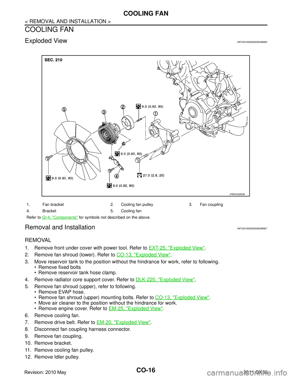
Exploded ViewINFOID:0000000006289666
Removal and InstallationINFOID:0000000006289667
REMOVAL
1. Remove front under cover with power tool. Refer to EXT-25, "Exploded View".
2. Remove fan shroud (lower). Refer to CO-13, "
Exploded View".
3. Move reservoir tank to the position without the hindrance for work, refer to following.
Remove fixed bolts
Remove reservoir tank hose clamp.
4. Remove radiator core support cover. Refer to DLK-220, "
Exploded View".
5. Remove fan shroud (upper), refer to following. Remove EVAP hose.
Remove fan shroud (upper) mounting bolts. Refer to CO-13, "
Exploded View".
Move air cleaner to the position without the hindrance for work.
Remove engine cover. Refer to EM-25, "
Exploded View".
6. Remove cooling fan.
7. Remove drive belt. Refer to EM-20, "
Exploded View".
8. Disconnect fan coupling harness connector.
9. Remove fan coupling.
10. Remove bracket.
11. Remove cooling fan pulley.
12. Remove Idler pulley.
1. Fan bracket 2. Cooling fan pulley 3. Fan coupling
4. Bracket 5. Cooling fan
Refer to GI-4, "
Components" for symbols not described on the above.
JPBIA3326GB
Revision: 2010 May2011 QX56
Page 959 of 5598
COOLING FANCO-17
< REMOVAL AND INSTALLATION >
C
DE
F
G H
I
J
K L
M A
CO
NP
O
13. Remove the fan bracket, refer to following.
Disconnect A/C compressor harness connector. Refer to HA-30, "
Exploded View".
Remove A/C compressor mounting bolt. Refer to HA-30, "
Exploded View".
Remove fan bracket mounting bolt.
INSTALLATION
Installation is in the reverse order of removal.
InspectionINFOID:0000000006289668
INSPECTION AFTER REMOVAL
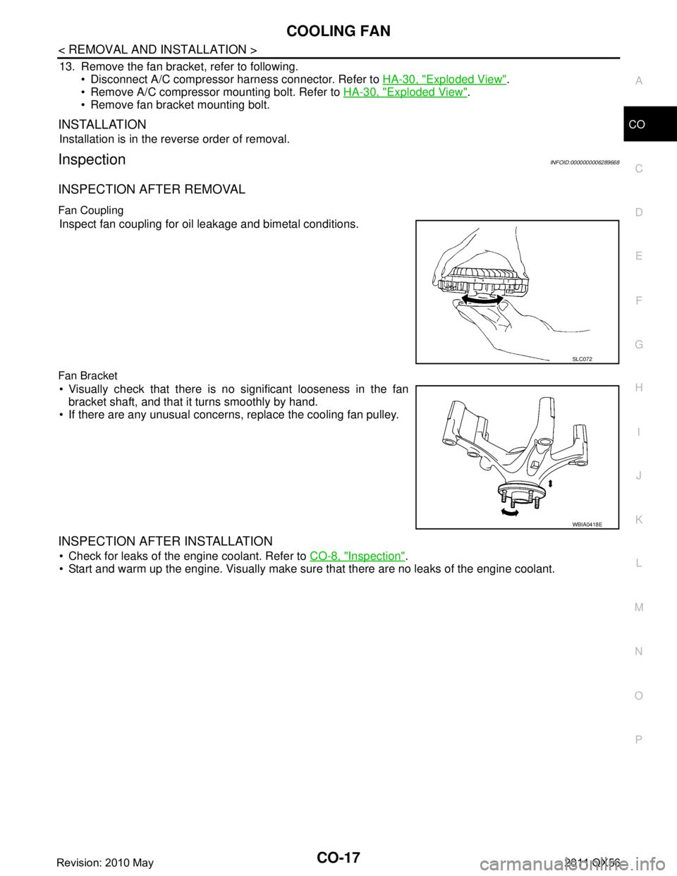
Fan Coupling
Inspect fan coupling for oil leakage and bimetal conditions.
Fan Bracket
Visually check that there is no significant looseness in the fan bracket shaft, and that it turns smoothly by hand.
If there are any unusual concerns, replace the cooling fan pulley.
INSPECTION AFTER INSTALLATION
Check for leaks of the engine coolant. Refer to CO-8, "Inspection".
Start and warm up the engine. Visually make sure that there are no leaks of the engine coolant.
SLC072
WBIA0418E
Revision: 2010 May2011 QX56
Page 960 of 5598
CO-18
< REMOVAL AND INSTALLATION >
WATER PUMP
WATER PUMP
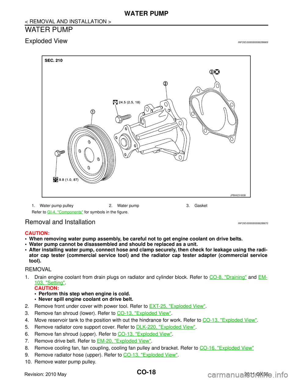
Exploded ViewINFOID:0000000006289669
Removal and InstallationINFOID:0000000006289670
CAUTION:
When removing water pump assembly, be careful not to get engine coolant on drive belts.
Water pump cannot be disassembled and should be replaced as a unit.
After installing water pump, co nnect hose and clamp securely, then check for leakage using the radi-
ator cap tester (commercial service tool) and the radiator cap tester adapter (commercial service
tool).
REMOVAL
1. Drain engine coolant from drain plugs on radiator and cylinder block. Refer to CO-8, "Draining" and EM-
103, "Setting".
CAUTION:
Perform this step when engine is cold.
Never spill engine coolant on drive belt.
2. Remove front under cover with power tool. Refer to EXT-25, "
Exploded View".
3. Remove fan shroud (lower). Refer to CO-13, "
Exploded View".
4. Move reservoir tank to the position with out the hindrance for work. Refer to CO-13, "
Exploded View".
5. Remove radiator core support cover. Refer to DLK-220, "
Exploded View".
6. Remove fan shroud (upper). Refer to CO-13, "
Exploded View".
7. Remove drive belt. Refer to EM-20, "
Exploded View".
8. Remove cooling fan, fan coupling, cooling fan pulley and bracket. Refer to CO-16, "
Exploded View"
9. Remove radiator hose (upper). Refer to CO-13, "Exploded View".
10. Remove water pump pulley.
1. Water pump pulley 2. Water pump 3. Gasket
Refer to GI-4, "
Components" for symbols in the figure.
JPBIA2316GB
Revision: 2010 May2011 QX56
Page 1330 of 5598
![INFINITI QX56 2011 Factory User Guide
DAS
C1B03 ABNRML TEMP DETECTDAS-365
< DTC/CIRCUIT DIAGNOSIS > [LDW & LDP]
C
D
E
F
G H
I
J
K L
M B
N P A
C1B03 ABNRML TEMP DETECT
ADAS CONTROL UNIT
ADAS CONTROL UNIT : DTC LogicINFOID:0000000006223771 INFINITI QX56 2011 Factory User Guide
DAS
C1B03 ABNRML TEMP DETECTDAS-365
< DTC/CIRCUIT DIAGNOSIS > [LDW & LDP]
C
D
E
F
G H
I
J
K L
M B
N P A
C1B03 ABNRML TEMP DETECT
ADAS CONTROL UNIT
ADAS CONTROL UNIT : DTC LogicINFOID:0000000006223771](/img/42/57033/w960_57033-1329.png)
DAS
C1B03 ABNRML TEMP DETECTDAS-365
< DTC/CIRCUIT DIAGNOSIS > [LDW & LDP]
C
D
E
F
G H
I
J
K L
M B
N P A
C1B03 ABNRML TEMP DETECT
ADAS CONTROL UNIT
ADAS CONTROL UNIT : DTC LogicINFOID:0000000006223771
DTC DETECTION LOGIC
ADAS CONTROL UNIT : Diagnosis ProcedureINFOID:0000000006223772
1.CHECK LANE CAMERA UNIT SELF-DIAGNOSIS RESULTS
1. Perform “All DTC R eading” with CONSULT-III.
2. Check if the “C1B03” is detected in “Self Diagnostic Result” of “LANE CAMERA”
Is
“C1B03” detected?
YES >> Refer to DAS-365, "LANE CAMERA UNIT : DTC Logic".
NO >> GO TO 2.
2.CHECK ADAS CONTROL UNIT SELF-DIAGNOSIS RESULTS
1. Erase all self-diagnosis results with CONSULT-III.
2. Perform “All DTC Reading”.
3. Check if the “C1B03” is detected in “Self Diagnostic Result” of “ICC/ADAS”
Is
“C1B03” detected?
YES >> Replace the ADAS control unit. Refer to DAS-63, "Removal and Installation".
NO >> INSPECTION END
LANE CAMERA UNIT
LANE CAMERA UNIT : DTC LogicINFOID:0000000006223773
DTC DETECTION LOGIC
LANE CAMERA UNIT : Diagnosis ProcedureINFOID:0000000006223774
1.COOLING LANE CAMERA UNIT
1. Wait for 10 minutes or more to cool the lane camera unit.
2. Erase All self-diagnosis results with CONSULT-III.
3. Perform “All DTC Reading”.
4. Check if the “C1B03” is detected in “Self Diagnostic Result” of “LANE CAMERA”.
Is
“C1B03” detected?
YES >> Replace the lane camera unit. Refer to DAS-403, "Removal and Installation".
NO >> INSPECTION END
DTC
(On board
display) Trouble diagnosis name DTC detecting condition Possible causes
C1B03 (83) CAM ABNRML TMP DETCT
Temperature around lane camera unit is ex-
cessively high Interior room temperature is exces-
sively high
DTC Trouble diagnosis name DTC detecting condition Possible causes
C1B03 ABNRML TEMP DETECT Temperature around lane camera unit is ex-
cessively high Interior room temperature is exces-
sively high
Revision: 2010 May2011 QX56
Page 1504 of 5598
DEF-12
< SYSTEM DESCRIPTION >
DIAGNOSIS SYSTEM (IPDM E/R)
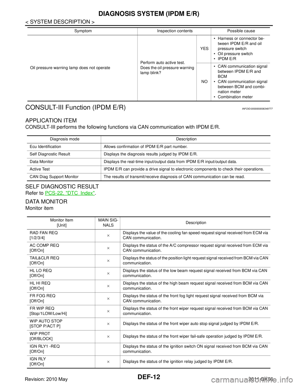
CONSULT-III Function (IPDM E/R)
INFOID:0000000006349777
APPLICATION ITEM
CONSULT-III performs the following functions via CAN communication with IPDM E/R.
SELF DIAGNOSTIC RESULT
Refer to PCS-22, "DTCIndex".
DATA MONITOR
Monitor item
Oil pressure warning lamp does not operate Perform auto active test.
Does the oil pressure warning
lamp blink?YES
Harness or connector be-
tween IPDM E/R and oil
pressure switch
Oil pressure switch
IPDM E/R
NO CAN communication signal
between IPDM E/R and
BCM
CAN communication signal
between BCM and combi-
nation meter
Combination meter
Symptom Inspection contents Possible cause
Diagnosis mode Description
Ecu Identification Allows confirmation of IPDM E/R part number.
Self Diagnostic Result Displays the diagnosis results judged by IPDM E/R.
Data Monitor Displays the real-time input/output data from IPDM E/R input/output data.
Active Test IPDM E/R can provide a drive signal to electronic components to check their operations.
CAN Diag Support Monitor The results of transmit/receive diagnosis of CAN communication can be read.
Monitor Item [Unit] MAIN SIG-
NALS Description
RAD FAN REQ
[1/2/3/4] ×Displays the value of the cooling fan speed request signal received from ECM via
CAN communication.
AC COMP REQ
[Off/On] ×Displays the status of the A/C compressor request signal received from ECM via
CAN communication.
TA I L & C L R R E Q
[Off/On] ×
Displays the status of the position light request signal received from BCM via CAN
communication.
HL LO REQ
[Off/On] ×Displays the status of the low beam request signal received from BCM via CAN
communication.
HL HI REQ
[Off/On] ×Displays the status of the high beam request signal received from BCM via CAN
communication.
FR FOG REQ
[Off/On] ×Displays the status of the front fog light request signal received from BCM via
CAN communication.
FR WIP REQ
[Stop/1LOW/Low/Hi] ×
Displays the status of the front wiper request signal received from BCM via CAN
communication.
WIP AUTO STOP
[STOP P/ACT P] ×
Displays the status of the front wiper auto stop signal judged by IPDM E/R.
WIP PROT
[Off/BLOCK] ×
Displays the status of the front wiper fail-safe operation judged by IPDM E/R.
IGN RLY1 -REQ
[Off/On] Displays the status of the ignition switch ON signal received from BCM via CAN
communication.
IGN RLY
[Off/On] ×
Displays the status of the ignition relay judged by IPDM E/R.
Revision: 2010 May2011 QX56
Page 1505 of 5598
![INFINITI QX56 2011 Factory User Guide
DIAGNOSIS SYSTEM (IPDM E/R)DEF-13
< SYSTEM DESCRIPTION >
C
DE
F
G H
I
J
K
M A
B
DEF
N
O P
ACTIVE TEST
Te s t i t e m
PUSH SW
[Off/On] Displays the status of the push-button ignition switch judged by INFINITI QX56 2011 Factory User Guide
DIAGNOSIS SYSTEM (IPDM E/R)DEF-13
< SYSTEM DESCRIPTION >
C
DE
F
G H
I
J
K
M A
B
DEF
N
O P
ACTIVE TEST
Te s t i t e m
PUSH SW
[Off/On] Displays the status of the push-button ignition switch judged by](/img/42/57033/w960_57033-1504.png)
DIAGNOSIS SYSTEM (IPDM E/R)DEF-13
< SYSTEM DESCRIPTION >
C
DE
F
G H
I
J
K
M A
B
DEF
N
O P
ACTIVE TEST
Te s t i t e m
PUSH SW
[Off/On] Displays the status of the push-button ignition switch judged by IPDM E/R.
INTER/NP SW
[Off/On] Displays the status of the shift position judged by IPDM E/R.
ST RLY CONT
[Off/On] Displays the status of the starter relay status signal received from BCM via CAN
communication.
IHBT RLY -REQ
[Off/On] Displays the status of the starter control relay signal received from BCM via CAN
communication.
ST/INHI RLY
[Off/ ST ON/INHI ON/UNKWN] Displays the status of the starter relay and starter control relay judged by IPDM
E/R.
DETENT SW
[Off/On] Displays the status of the A/T shift selector (detention switch) judged by IPDM E/
R.
S/L RLY -REQ
[Off/On] Displays the status of the steering lock relay signal received from BCM via CAN
communication.
S/L STATE
[LOCK/UNLK/UNKWN] Displays the status of the steering lock judged by IPDM E/R.
OIL P SW
[Open/Close] Displays the status of the oil pressure switch judged by IPDM E/R.
HOOD SW
[Off/On] Displays the status of the hood switch judged by IPDM E/R.
HL WASHER REQ
[Off/On] Displays the status of the headlamp washer request signal received from BCM via
CAN communication.
THFT HRN REQ
[Off/On] Displays the status of the theft warning horn request signal received from BCM
via CAN communication.
HORN CHIRP
[Off/On] Displays the status of the horn reminder signal received from BCM via CAN com-
munication.
Monitor Item
[Unit] MAIN SIG-
NALS Description
Test item Operation Description
CORNERING LAMP LH
NOTE:
This item is indicated, but cannot be tested.
RH
HORN On Operates horn relay for 20 ms.
REAR DEFOGGER Off OFF
On Operates the rear window defogger relay.
FRONT WIPER Off OFF
Lo Operates the front wiper relay.
Hi Operates the front wiper relay and front wiper high relay.
MOTOR FAN* 1OFF
2 Transmits 50% pulse duty signal (PWM signal) to the cooling fan control module.
3 Transmits 75% pulse duty signal (PWM signal) to the cooling fan control module.
4
Transmits 100% pulse duty signal (PWM signal) to the cooling fan control mod-
ule.
HEAD LAMP WASHER On Operates the headlamp washer relay for 1 second.
Revision: 2010 May2011 QX56
Page 2025 of 5598
EC-1
ENGINE
C
DE
F
G H
I
J
K L
M
SECTION EC
A
EC
N
O P
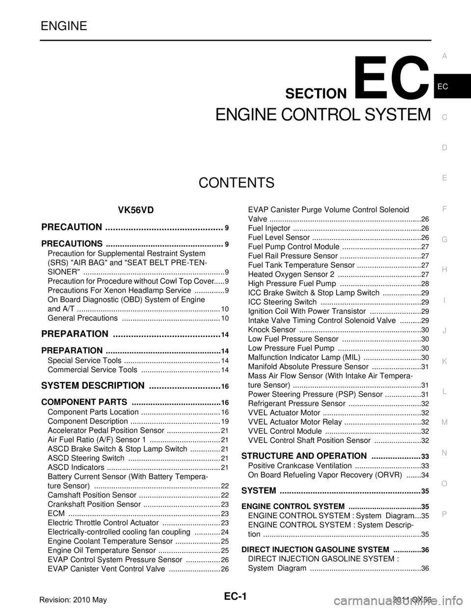
CONTENTS
ENGINE CONTROL SYSTEM
VK56VD
PRECAUTION ................ ...............................
9
PRECAUTIONS .............................................. .....9
Precaution for Supplemental Restraint System
(SRS) "AIR BAG" and "SEAT BELT PRE-TEN-
SIONER" ............................................................. ......
9
Precaution for Procedure without Cowl Top Cover ......9
Precautions For Xenon Headlamp Service ...............9
On Board Diagnostic (OBD) System of Engine
and A/T ....................................................................
10
General Precautions ...............................................10
PREPARATION ...........................................14
PREPARATION .............................................. ....14
Special Service Tools .......................................... ....14
Commercial Service Tools ......................................14
SYSTEM DESCRIPTION .............................16
COMPONENT PARTS ................................... ....16
Component Parts Location .................................. ....16
Component Description ...........................................19
Accelerator Pedal Position Sensor ..........................21
Air Fuel Ratio (A/F) Sensor 1 ..................................21
ASCD Brake Switch & Stop Lamp Switch ...............21
ASCD Steering Switch ............................................21
ASCD Indicators ......................................................21
Battery Current Sensor (With Battery Tempera-
ture Sensor) ............................................................
22
Camshaft Position Sensor .......................................22
Crankshaft Position Sensor .....................................23
ECM ........................................................................23
Electric Throttle Control Actuator ............................23
Electrically-controlled cooling fan coupling .............24
Engine Coolant Temperature Sensor ......................25
Engine Oil Temperature Sensor ..............................25
EVAP Control System Pressure Sensor .................26
EVAP Canister Vent Control Valve .........................26
EVAP Canister Purge Volume Control Solenoid
Valve .................................................................... ....
26
Fuel Injector .............................................................26
Fuel Level Sensor ....................................................26
Fuel Pump Control Module ......................................27
Fuel Rail Pressure Sensor .......................................27
Fuel Tank Temperature Sensor ...............................27
Heated Oxygen Sensor 2 ........................................27
High Pressure Fuel Pump .......................................28
ICC Brake Switch & Stop Lamp Switch ...................29
ICC Steering Switch ................................................29
Ignition Coil With Power Transistor .........................29
Intake Valve Timing Control Solenoid Valve ...........29
Knock Sensor ...................................................... ....30
Low Fuel Pressure Sensor ......................................30
Low Pressure Fuel Pump ........................................30
Malfunction Indicator Lamp (MIL) ............................30
Manifold Absolute Pressure Sensor ........................31
Mass Air Flow Sensor (With Intake Air Tempera-
ture Sensor) .............................................................
31
Power Steering Pressure (PSP) Sensor ..................31
Refrigerant Pressure Sensor ............................... ....32
VVEL Actuator Motor ...............................................32
VVEL Actuator Motor Relay .....................................32
VVEL Control Module ..............................................32
VVEL Control Shaft Position Sensor .......................32
STRUCTURE AND OPERATION .....................33
Positive Crankcase Ventilation ................................33
On Board Refueling Vapor Recovery (ORVR) ........34
SYSTEM ............................................................35
ENGINE CONTROL SYSTEM ........................ ...........35
ENGINE CONTROL SYSTEM : System Diagram ....35
ENGINE CONTROL SYSTEM : System Descrip-
tion ...........................................................................
35
DIRECT INJECTION GASOLINE SYSTEM .......... ....36
DIRECT INJECTION GASOLINE SYSTEM :
System Diagram .....................................................
36
Revision: 2010 May2011 QX56
Page 2026 of 5598

EC-2
DIRECT INJECTION GASOLINE SYSTEM : Sys-
tem Description .......................................................
36
FUEL PRESSURE CONTROL ..................................39
FUEL PRESSURE CONTROL : System Diagram
...
39
FUEL PRESSURE CONTROL : System Descrip-
tion ..........................................................................
39
COOLING FAN CONTROL .................................... ...40
COOLING FAN CONTROL : System Diagram .......41
COOLING FAN CONTROL : System Description ...41
ELECTRIC IGNITION SYST EM ................................41
ELECTRIC IGNITION SYSTEM :
System Diagram ................................................. ...
42
ELECTRIC IGNITION SYSTEM : System De-
scription ..................................................................
42
INTAKE VALVE TIMING CONTROL ..................... ...43
INTAKE VALVE TIMING CONTROL : System Di-
agram .....................................................................
43
INTAKE VALVE TIMING CONTROL : System De-
scription ..................................................................
43
VVEL SYSTEM ....................................... ...................43
VVEL SYSTEM : System Dia gram ........................44
VVEL SYSTEM : System De scription .....................44
EVAPORATIVE EMISSION SYSTEM .................... ...45
EVAPORATIVE EMISSION SYSTEM : System
Diagram ..................................................................
45
EVAPORATIVE EMISSION SYSTEM : System
Description ..............................................................
45
AIR CONDITIONING CUT CONTROL ................... ...46
AIR CONDITIONING CUT CONTROL : System
Diagram ..................................................................
47
AIR CONDITIONING CUT CONTROL : System
Description ..............................................................
47
AUTOMATIC SPEED CONTROL DEVICE (ASCD) ...47
AUTOMATIC SPEED CONTROL DEVICE (AS-
CD) : System Diagram ............................................
48
AUTOMATIC SPEED CONTROL DEVICE (AS-
CD) : System Description .......................................
48
CAN COMMUNICATION ........................................ ...48
CAN COMMUNICATION : System Description ......48
OPERATION ................................................... ...49
AUTMATIC SPEED CONTROL DEVICE (ASCD) . ...49
AUTMATIC SPEED CONTROL DEVICE (ASCD)
: Switch Name and Function ...................................
49
ON BOARD DIAGNOSTIC (OBD) SYSTEM .....51
Diagnosis Description .......................................... ...51
GST (Generic Scan Tool) .......................................51
DIAGNOSIS SYSTEM (ECM) ............................52
DIAGNOSIS DESCRIPTION .................................. ...52
DIAGNOSIS DESCRIPTION : 1st Trip Detection
Logic and Two Trip Detection Logic ........................
52
DIAGNOSIS DESCRIPTION : DTC and Freeze
Frame Data .............................................................
52
DIAGNOSIS DESCRIPTION : Counter System ......53
DIAGNOSIS DESCRIPTION : Driving Pattern ........58
DIAGNOSIS DESCRIPTION : System Readiness
Test (SRT) Code .................................................. ...
58
DIAGNOSIS DESCRIPTION : Malfunction Indica-
tor Lamp (MIL) ..................................................... ...
60
On Board Diagnosis Function .................................60
CONSULT-III Function ............................................63
ECU DIAGNOSIS INFORMATION .............72
ECM ................................................................ ...72
Reference Value .................................................. ...72
Fail-safe ..................................................................93
DTC Inspection Priority Chart .................................96
DTC Index ...............................................................98
Test Value and Test Limit ..................................104
VVEL CONTROL MODULE .............................110
Reference Value .................................................. .110
WIRING DIAGRAM ...................................114
ENGINE CONTROL SYSTEM ........................ ..114
Wiring Diagram .................................................... .114
BASIC INSPECTION .................................135
DIAGNOSIS AND REPAIR WORKFLOW ...... ..135
Work Flow ............................................................ .135
Diagnostic Work Sheet .........................................138
BASIC INSPECTION ...................................... ..139
Work Procedure ................................................... .139
ADDITIONAL SERVICE WHEN REPLACING
ECM ..................................................................
143
Description ........................................................... .143
Work Procedure ....................................................143
ADDITIONAL SERVICE WHEN REPLACING
VVEL CONTROL MODULE .............................
144
Description ........................................................... .144
Work Procedure ....................................................144
VIN REGISTRATION ........................................145
Description ........................................................... .145
Work Procedure ....................................................145
ACCELERATOR PEDAL RELEASED POSI-
TION LEARNING ............................................ ..
146
Description ........................................................... .146
Work Procedure ....................................................146
THROTTLE VALVE CLOSED POSITION
LEARNING .......................................................
147
Description ........................................................... .147
Revision: 2010 May2011 QX56