door INFINITI QX56 2011 Factory Service Manual
[x] Cancel search | Manufacturer: INFINITI, Model Year: 2011, Model line: QX56, Model: INFINITI QX56 2011Pages: 5598, PDF Size: 94.53 MB
Page 457 of 5598
BCS
INSPECTION AND ADJUSTMENTBCS-69
< BASIC INSPECTION >
C
DE
F
G H
I
J
K L
B A
O P
N
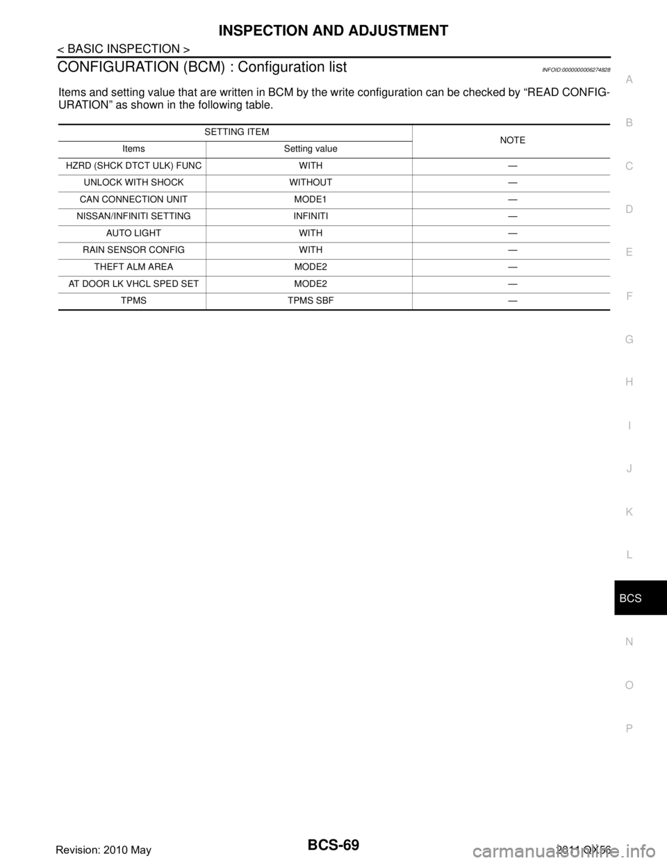
CONFIGURATION (BCM)
: Configuration listINFOID:0000000006274828
Items and setting value that are written in BCM by t he write configuration can be checked by “READ CONFIG-
URATION” as shown in the following table.
SETTING ITEM NOTE
Items Setting value
HZRD (SHCK DTCT ULK) FUNC WITH — UNLOCK WITH SHOCK WITHOUT —
CAN CONNECTION UNIT MODE1 —
NISSAN/INFINITI SETTING INFINITI — AUTO LIGHT WITH —
RAIN SENSOR CONFIG WITH — THEFT ALM AREA MODE2 —
AT DOOR LK VHCL SPED SET MODE2 — TPMS TPMS SBF —
Revision: 2010 May2011 QX56
Page 583 of 5598
![INFINITI QX56 2011 Factory Service Manual
BRC-66
< BASIC INSPECTION >[WITH VDC]
CALIBRATION OF DECEL G SENSOR
CALIBRATION OF DECEL G SENSOR
DescriptionINFOID:0000000006222590
CAUTION:
Always perform the decel G sensor cal
ibration before dri INFINITI QX56 2011 Factory Service Manual
BRC-66
< BASIC INSPECTION >[WITH VDC]
CALIBRATION OF DECEL G SENSOR
CALIBRATION OF DECEL G SENSOR
DescriptionINFOID:0000000006222590
CAUTION:
Always perform the decel G sensor cal
ibration before dri](/img/42/57033/w960_57033-582.png)
BRC-66
< BASIC INSPECTION >[WITH VDC]
CALIBRATION OF DECEL G SENSOR
CALIBRATION OF DECEL G SENSOR
DescriptionINFOID:0000000006222590
CAUTION:
Always perform the decel G sensor cal
ibration before driving when the following operation is per-
formed.
NOTE:
Yaw rate/side/decel G sensor calibration is performed when performing the decel G sensor calibration.
× : Required —: Not required
Work ProcedureINFOID:0000000006222591
Decel G sensor calibration
CAUTION:
Always use CONSULT-III for the d ecel G sensor calibration. (It cannot be adjusted other than with
CONSULT-III.)
NOTE:
Yaw rate/side/decel G sensor calibration is performed when performing the decel G sensor calibration.
1.CHECK THE VEHICLE STATUS
1. Steer the steering wheel to the straight- ahead position. Stop the vehicle on level surface.
2. Stop the engine.
3. Turn the ignition switch OFF.
Is the vehicle stopped in the straight-ahead position on level surface?
YES >> GO TO 2.
NO >> Steer the steering wheel to the straight- ahead position. Stop the vehicle on level surface.
2.PERFORM DECEL G SENSOR CALIBRATION
CAUTION:
Never allow passenger or load on the vehicle.
Never apply vibration to the vehicle body when opening or closing door during calibration.
With CONSULT-III.
1. Turn the ignition switch ON.
CAUTION:
Never start engine.
2. Select “ABS”, “WORK SUPPORT”, “DECEL G-SENSOR CALIBRATION” in this order.
3. Select “START”.
4. After approx. 10 seconds, select “END”.
5. Turn ignition switch OFF and then turn it ON again. CAUTION:
Be sure to perform the operation above.
Procedure Decel G sensor calibration
Removing/ installing ABS actuator and electric unit (control unit) —
Replacing ABS actuator and electric unit (control unit) ×
Removing/installing steering components —
Replacing steering components —
Removing/installing suspension components —
Replacing suspension components —
Removing/installing tire —
Replacing tire —
Tire rotation —
Adjusting wheel alignment. —
Removing/installing yaw rate/side/decel G sensor ×
Replacing yaw rate/side/decel G sensor ×
Revision: 2010 May2011 QX56
Page 676 of 5598
BRM-1
BODY EXTERIOR, DOORS, ROOF & VEHICLE SECURITY
C
D
E
F
G H
I
J
L
M
SECTION BRM
A
B
BRM
N
O P
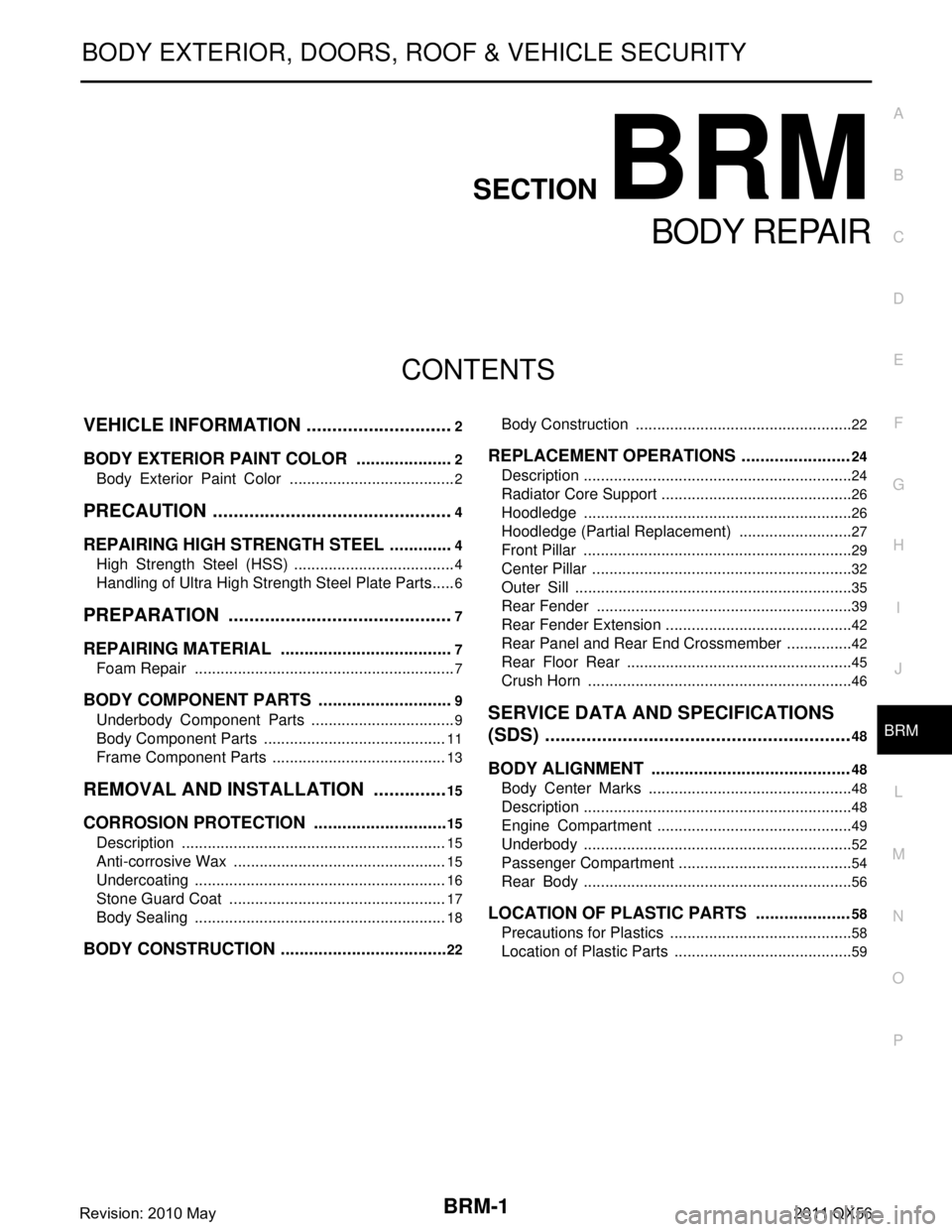
CONTENTS
BODY REPAIR
VEHICLE INFORMATION ... ..........................2
BODY EXTERIOR PAINT COLOR ................ .....2
Body Exterior Paint Color ................................. ......2
PRECAUTION ...............................................4
REPAIRING HIGH STRENGTH STEEL ......... .....4
High Strength Steel (HSS) ................................ ......4
Handling of Ultra High Strength Steel Plate Parts ......6
PREPARATION ............................................7
REPAIRING MATERIAL ................................ .....7
Foam Repair ....................................................... ......7
BODY COMPONENT PARTS .............................9
Underbody Component Parts ............................ ......9
Body Component Parts ...........................................11
Frame Component Parts .........................................13
REMOVAL AND INSTALLATION ...............15
CORROSION PROTECTION ......................... ....15
Description .......................................................... ....15
Anti-corrosive Wax ..................................................15
Undercoating ...........................................................16
Stone Guard Coat ...................................................17
Body Sealing ...........................................................18
BODY CONSTRUCTION ....................................22
Body Construction ............................................... ....22
REPLACEMENT OPERATIONS .......................24
Description ...............................................................24
Radiator Core Support .............................................26
Hoodledge ...............................................................26
Hoodledge (Partial Replacement) ...........................27
Front Pillar ...............................................................29
Center Pillar .............................................................32
Outer Sill .................................................................35
Rear Fender ............................................................39
Rear Fender Extension ............................................42
Rear Panel and Rear End Crossmember ................42
Rear Floor Rear .....................................................45
Crush Horn ..............................................................46
SERVICE DATA AND SPECIFICATIONS
(SDS) ............... .............................................
48
BODY ALIGNMENT ..........................................48
Body Center Marks ............................................ ....48
Description ...............................................................48
Engine Compartment ..............................................49
Underbody ...............................................................52
Passenger Compartment .........................................54
Rear Body ...............................................................56
LOCATION OF PLASTIC PARTS ....................58
Precautions for Plastics ...........................................58
Location of Plastic Parts ..........................................59
Revision: 2010 May2011 QX56
Page 677 of 5598
BRM-2
< VEHICLE INFORMATION >
BODY EXTERIOR PAINT COLOR
VEHICLE INFORMATION
BODY EXTERIOR PAINT COLOR
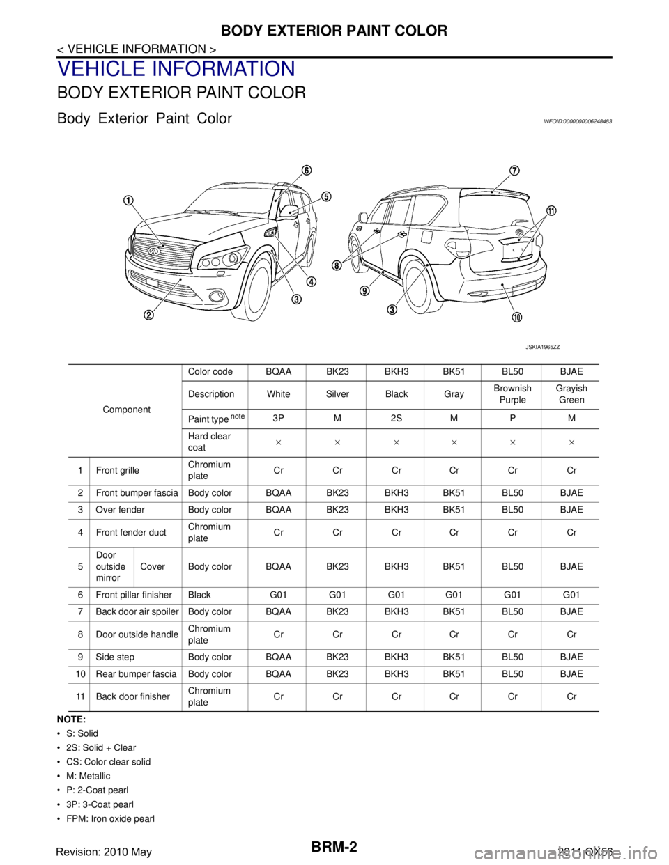
Body Exterior Paint ColorINFOID:0000000006248483
NOTE:
•S: Solid
2S: Solid + Clear
CS: Color clear solid
M: Metallic
P: 2-Coat pearl
3P: 3-Coat pearl
FPM: Iron oxide pearl Component
Color code BQAA BK23 BKH3 BK51 BL50 BJAE
Description White Silver Black Gray
Brownish
Purple Grayish
Green
Paint type
note3P M 2S M P M
Hard clear
coat ××××××
1 Front grille Chromium
plateCr Cr Cr Cr Cr Cr
2 Front bumper fascia Body color BQAA BK23 BKH3 BK51 BL50 BJAE
3 Over fender Body color B QAA BK23 BKH3 BK51 BL50 BJAE
4 Front fender duct Chromium
plate
Cr Cr Cr Cr Cr Cr
5 Door
outside
mirror
Cover Body color BQAA BK23 BKH3 BK51 BL50 BJAE
6 Front pillar finisher Black G01 G01 G01 G01 G01 G01
7 Back door air spoiler Body color BQAA BK23 BKH3 BK51 BL50 BJAE
8 Door outside handle Chromium
plate
Cr Cr Cr Cr Cr Cr
9 Side step Body color BQAA BK23 BKH3 BK51 BL50 BJAE
10 Rear bumper fascia Body color BQAA BK23 BKH3 BK51 BL50 BJAE
11 Back door finisher Chromium
plateCr Cr Cr Cr Cr Cr
JSKIA1965ZZ
Revision: 2010 May2011 QX56
Page 687 of 5598

BRM-12
< PREPARATION >
BODY COMPONENT PARTS
NOTE:
For the parts without a number described in the figure, it is supplied only with the assembly part that the part is included with.
Tensile strength column shows the largest strength value of a part in the component part. No. Parts name
Tensile strength
(MPa) Both sided anti-corrosive
precoated steel sections
1. Hood Under 440×
2. Front fender (RH & LH) Under 440 ×
3. Inner side roof rail (RH & LH) 590 —
4. Upper inner front pillar (RH & LH) c. T=1.6 mm
(0.063 in)
980
caution—
5. Inner center pillar (RH & LH) d. T=1.6 mm
(0.063 in)
980
caution×
6. Center sill reinforcement assembly (RH & LH) Under 440 ×
7. Side body assembly (RH & LH) Refer to No.8 −13
8. Upper front pillar reinforcement (RH & LH) 590 —
9. Lower center pillar brace (RH & LH) e. T=1.8 mm
(0.071 in)
980
caution—
10. Front pillar brace (RH & LH) 590 —
11. Outer sill reinforcement (RH & LH) 590 ×
12. Outer front side body (RH & LH) Under 440 ×
13. Front fender bracket assembly (RH & LH) Under 440 ×
14. Outer sill (RH & LH) Under 440 ×
15. Front door assembly (RH & LH) 440 ×
16. Outer front door panel (RH & LH) Under 440 ×
17. Rear door assembly (RH & LH) 440 ×
18. Outer rear door panel (RH & LH) Under 440 ×
19. Back pillar reinforcement (RH & LH) Under 440 —
20. Inner back pillar (RH & LH) Under 440 —
21. Inner rear side roof rail (RH & LH) Under 440 —
22. Inner rear pillar (RH & LH) 590 —
23. Lower inner rear pillar (RH & LH)v Under 440 —
24. Side panel reinforcement (RH & LH) Under 440 —
25. Outer rear wheelhouse (RH & LH) Under 440 ×
26. Inner rear wheelhouse (RH & LH) Under 440 ×
27. Outer rear wheelhouse extension (RH & LH) Under 440 ×
28. Roof assembly Under 440 —
29. Front roof rail 440 —
30. Roof bow No.3 Under 440 —
31. Roof bow No.4 Under 440 —
32. Roof bow No.5 Under 440 —
33. Rear roof rail 440 —
34. Rear fender (RH & LH) Under 440 ×
35. Back pillar assembly (RH & LH) Under 440 —
36. Rear fender bracket (RH & LH) Under 440 —
37. Fuel filler lid Under 440 ×
38. Rear fender extension (RH & LH) Under 440 ×
39. Back door Under 440 ×
Revision: 2010 May2011 QX56
Page 690 of 5598
CORROSION PROTECTIONBRM-15
< REMOVAL AND INSTALLATION >
C
DE
F
G H
I
J
L
M A
B
BRM
N
O P
REMOVAL AND INSTALLATION
CORROSION PROTECTION
DescriptionINFOID:0000000006248490
To provide improved corrosion prevention, the follo wing anti-corrosive measures have been implemented in
NISSAN production plants. When repairing or replacing body panels, it is necessary to use the same anti-cor-
rosive measures.
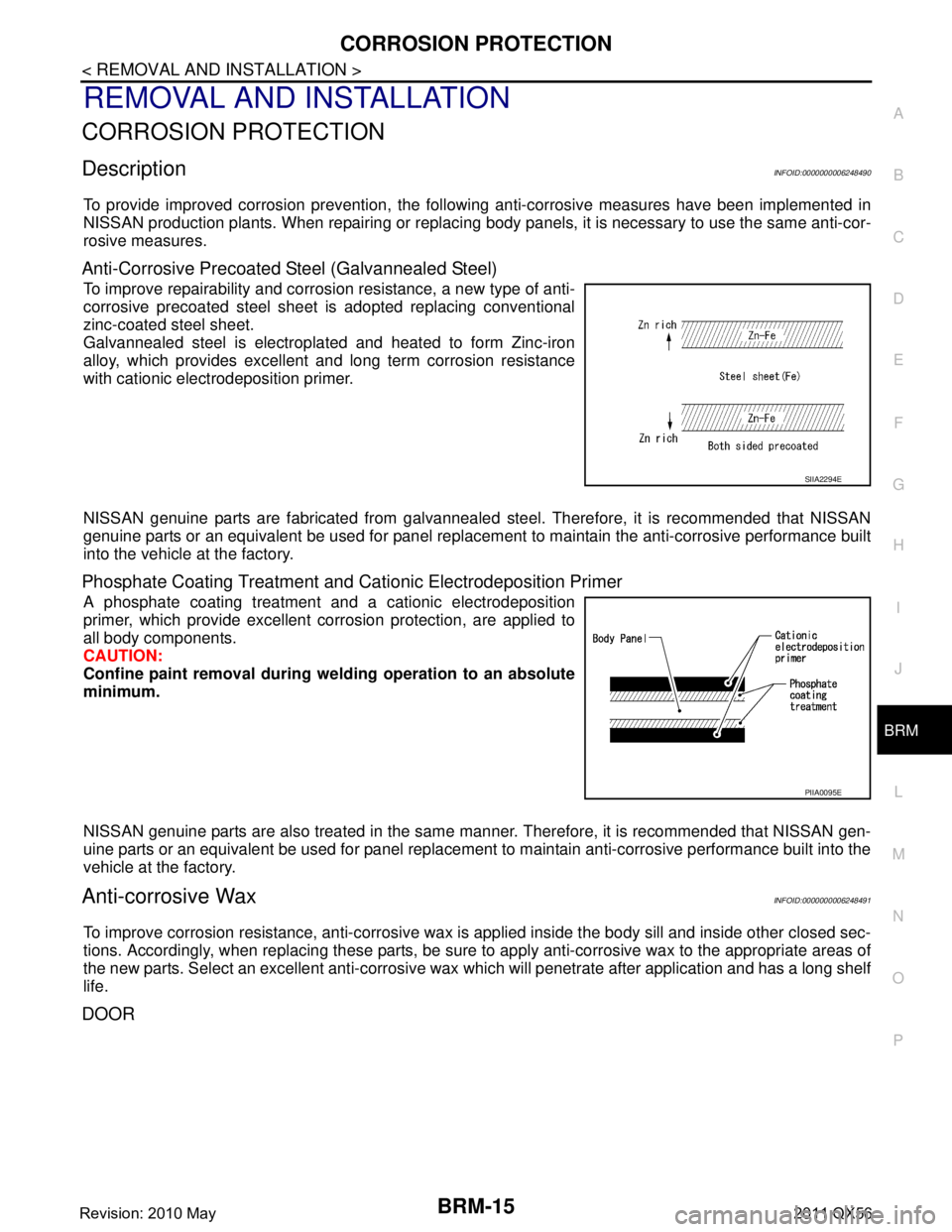
Anti-Corrosive Precoated Steel (Galvannealed Steel)
To improve repairability and corrosi on resistance, a new type of anti-
corrosive precoated steel sheet is adopted replacing conventional
zinc-coated steel sheet.
Galvannealed steel is electroplated and heated to form Zinc-iron
alloy, which provides excellent and long term corrosion resistance
with cationic electrodeposition primer.
NISSAN genuine parts are fabricated from galvannealed steel. Therefore, it is recommended that NISSAN
genuine parts or an equivalent be used for panel replacem ent to maintain the anti-corrosive performance built
into the vehicle at the factory.
Phosphate Coating Treatment and Cationic Electrodeposition Primer
A phosphate coating treatment and a cationic electrodeposition
primer, which provide excellent corrosion protection, are applied to
all body components.
CAUTION:
Confine paint removal during we lding operation to an absolute
minimum.
NISSAN genuine parts are also treated in the same manner. Therefore, it is recommended that NISSAN gen-
uine parts or an equivalent be used for panel replacement to maintain anti-corrosive performance built into the
vehicle at the factory.
Anti-corrosive WaxINFOID:0000000006248491
To improve corrosion resistance, anti-corrosive wax is applied inside the body sill and inside other closed sec-
tions. Accordingly, when replacing these parts, be sure to apply anti-corrosive wax to the appropriate areas of
the new parts. Select an excellent anti-corrosive wax which will penetrate after application and has a long shelf
life.
DOOR
SIIA2294E
PIIA0095E
Revision: 2010 May2011 QX56
Page 692 of 5598
CORROSION PROTECTIONBRM-17
< REMOVAL AND INSTALLATION >
C
DE
F
G H
I
J
L
M A
B
BRM
N
O P
Stone Guard CoatINFOID:0000000006248493
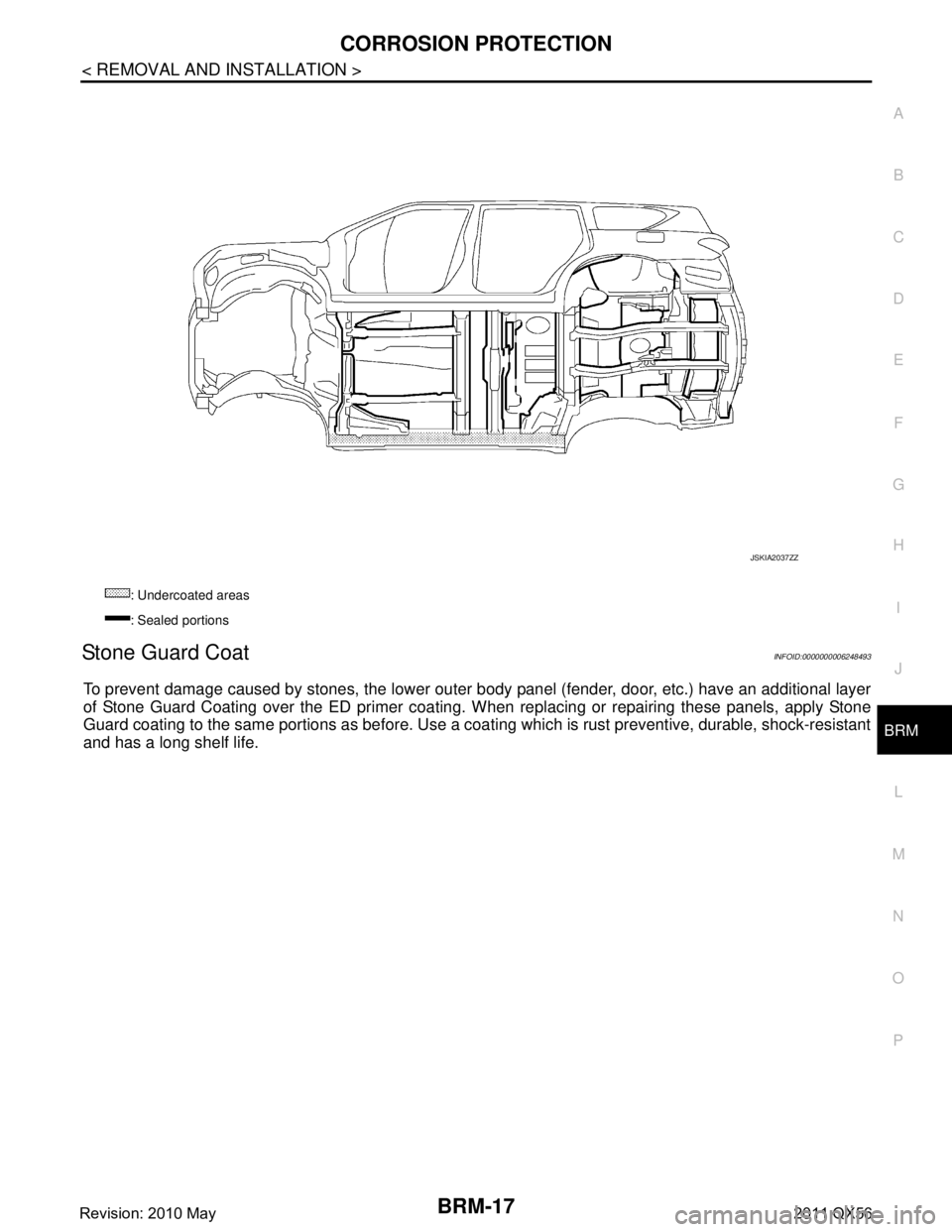
To prevent damage caused by stones, the lower outer body panel (fender, door, etc.) have an additional layer
of Stone Guard Coating over the ED primer coating. When replacing or repairing these panels, apply Stone
Guard coating to the same portions as before. Use a c oating which is rust preventive, durable, shock-resistant
and has a long shelf life.
: Undercoated areas
: Sealed portions
JSKIA2037ZZ
Revision: 2010 May2011 QX56
Page 731 of 5598
BRM-56
< SERVICE DATA AND SPECIFICATIONS (SDS)
BODY ALIGNMENT
Unit: mm (in)
Rear BodyINFOID:0000000006248512
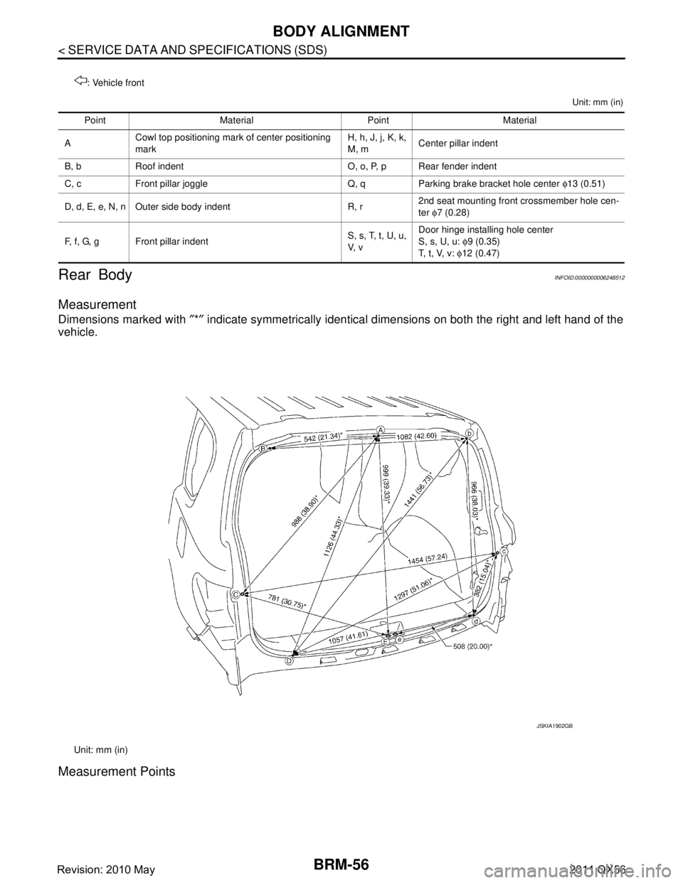
Measurement
Dimensions marked with ″*″ indicate symmetrically identical dimensions on both the right and left hand of the
vehicle.
Measurement Points
: Vehicle front
Point Material Point Material
A Cowl top positioning mark of center positioning
mark H, h, J, j, K, k,
M, m
Center pillar indent
B, b Roof indent O, o, P, p Rear fender indent
C, c Front pillar joggle Q, q Parking brake bracket hole center φ13 (0.51)
D, d, E, e, N, n Outer side body indent R, r 2nd seat mounting front crossmember hole cen-
ter
φ7 (0.28)
F, f, G, g Front pillar indent S, s, T, t, U, u,
V, vDoor hinge installing hole center
S, s, U, u:
φ9 (0.35)
T, t, V, v: φ12 (0.47)
Unit: mm (in)
JSKIA1902GB
Revision: 2010 May2011 QX56
Page 734 of 5598
LOCATION OF PLASTIC PARTSBRM-59
< SERVICE DATA AND SPECIFICATIONS (SDS)
C
DE
F
G H
I
J
L
M A
B
BRM
N
O P
Location of Plastic PartsINFOID:0000000006248514
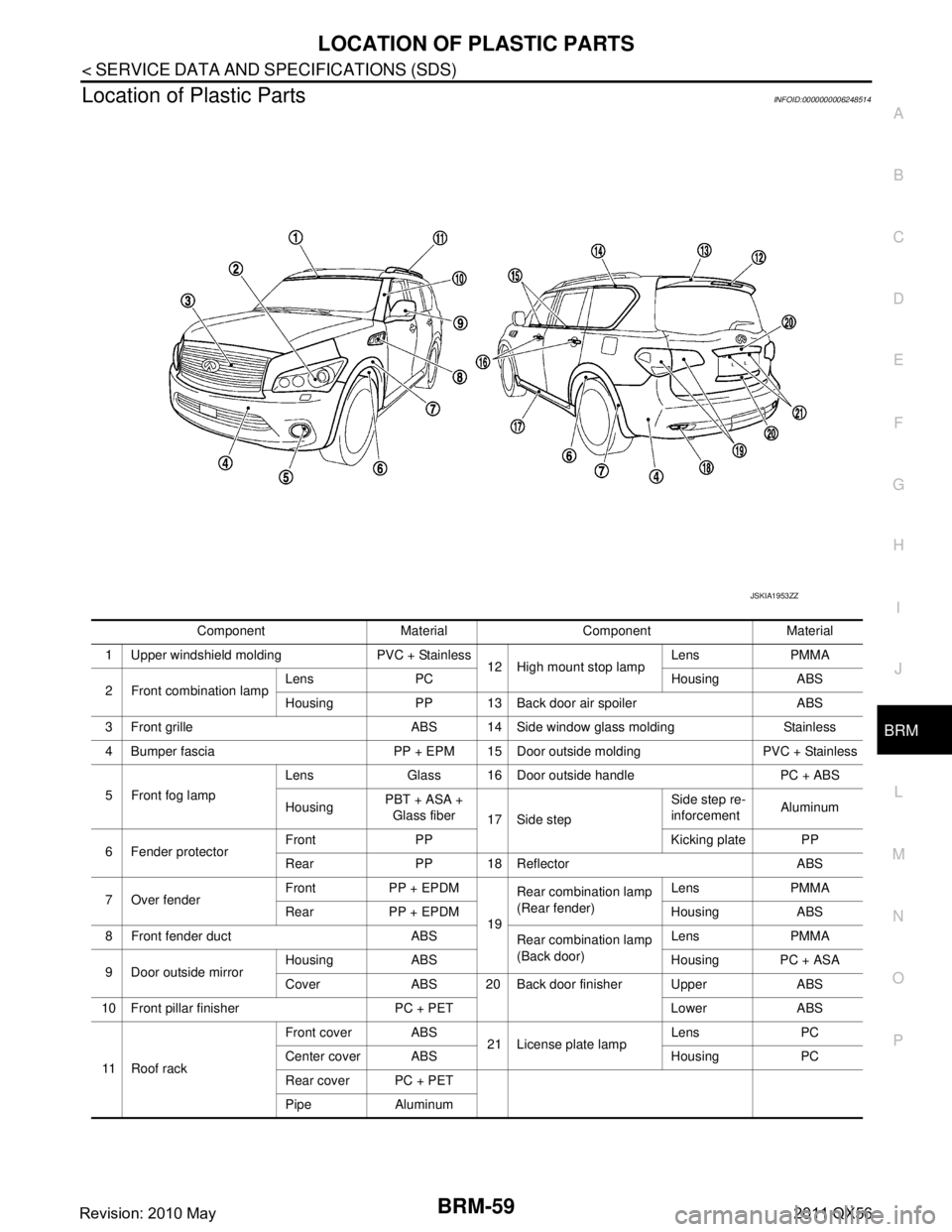
Component Material Component Material
1 Upper windshield molding PVC + Stainless 12 High mount stop lampLens PMMA
2 Front combination lamp Lens PC Housing ABS
Housing PP 13 Back door air spoiler ABS
3 Front grille ABS 14 Side window glass molding Stainless
4 Bumper fascia PP + EPM 15 Door outside molding PVC + Stainless
5 Front fog lamp Lens Glass 16 Door outside handle PC + ABS
Housing
PBT + ASA +
Glass fiber 17 Side step Side step re-
inforcement
Aluminum
6 Fender protector Front PP Kicking plate PP
Rear PP 18 Reflector ABS
7 Over fender Front PP + EPDM
19Rear combination lamp
(Rear fender)
Lens PMMA
Rear PP + EPDM Housing ABS
8 Front fender duct ABS Rear combination lamp
(Back door)Lens PMMA
9 Door outside mirror Housing ABS Housing PC + ASA
Cover ABS 20 Back door finisher Upper ABS
10 Front pillar finisher PC + PET Lower ABS
11 R o o f r a c k Front cover ABS
21 License plate lampLens PC
Center cover ABS Housing PC
Rear cover PC + PET
Pipe Aluminum
JSKIA1953ZZ
Revision: 2010 May2011 QX56
Page 1236 of 5598
![INFINITI QX56 2011 Factory Service Manual
DAS
WARNING SYSTEMS SWITCHDAS-271
< REMOVAL AND INSTALLATION > [FCW]
C
D
E
F
G H
I
J
K L
M B
N P A
REMOVAL AND INSTALLATION
WARNING SYSTEMS SWITCH
Removal and InstallationINFOID:0000000006223696
REMO INFINITI QX56 2011 Factory Service Manual
DAS
WARNING SYSTEMS SWITCHDAS-271
< REMOVAL AND INSTALLATION > [FCW]
C
D
E
F
G H
I
J
K L
M B
N P A
REMOVAL AND INSTALLATION
WARNING SYSTEMS SWITCH
Removal and InstallationINFOID:0000000006223696
REMO](/img/42/57033/w960_57033-1235.png)
DAS
WARNING SYSTEMS SWITCHDAS-271
< REMOVAL AND INSTALLATION > [FCW]
C
D
E
F
G H
I
J
K L
M B
N P A
REMOVAL AND INSTALLATION
WARNING SYSTEMS SWITCH
Removal and InstallationINFOID:0000000006223696
REMOVAL
1. Remove the instrument lower panel (LH). Refer to IP-14, "Removal and Installation".
2. Remove warning systems switch from instrument driver lower panel.
NOTE:
Warning systems switch and automatic back door switch are integrated.
INSTALLATION
Install in the reverse order of removal.
Revision: 2010 May2011 QX56