door INFINITI QX56 2011 Factory Service Manual
[x] Cancel search | Manufacturer: INFINITI, Model Year: 2011, Model line: QX56, Model: INFINITI QX56 2011Pages: 5598, PDF Size: 94.53 MB
Page 1539 of 5598

DLK-3
C
DE
F
G H
I
J
L
M A
B
DLK
N
O P
Diagnosis Procedure ...........................................
....
98
B2423 AUTOMATIC BACK DOOR MOTOR
OPERATION TIME .............................................
99
DTC Logic ........................................................... ....99
Diagnosis Procedure ...............................................99
B2424 CLOSURE CONDITION ........................100
DTC Logic ........................................................... ..100
Diagnosis Procedure .............................................100
Component Inspection ..........................................101
B2425 AUTOMATIC BACK DOOR CONTROL
UNIT ..................................................................
103
DTC Logic ........................................................... ..103
Diagnosis Procedure .............................................103
B2621 INSIDE ANTENNA ................................104
DTC Logic ........................................................... ..104
Diagnosis Procedure .............................................104
B2622 INSIDE ANTENNA ................................106
DTC Logic ........................................................... ..106
Diagnosis Procedure .............................................106
B2623 INSIDE ANTENNA ................................108
DTC Logic ........................................................... ..108
Diagnosis Procedure .............................................108
B2626 OUTSIDE ANTENNA ............................110
DTC Logic ........................................................... ..110
Diagnosis Procedure .............................................110
B2627 OUTSIDE ANTENNA ............................112
DTC Logic ........................................................... ..112
Diagnosis Procedure .............................................112
B2628 OUTSIDE ANTENNA ............................114
DTC Logic ........................................................... ..114
Diagnosis Procedure .............................................114
POWER SUPPLY AND GROUND CIRCUIT ....116
AUTOMATIC BACK DOOR CONTROL UNIT ...... ..116
AUTOMATIC BACK DOOR CONTROL UNIT : Di-
agnosis Procedure ................................................
116
DOOR SWITCH ................................................117
Component Function Check .............................. ..117
Diagnosis Procedure .............................................117
Component Inspection ..........................................119
BACK DOOR SWITCH .....................................120
Component Function Check .............................. ..120
Diagnosis Procedure .............................................120
Component Inspection ..........................................121
DOOR LOCK AND UNLOCK SWITCH ............122
DRIVER SIDE ........................................................ ..122
DRIVER SIDE : Component Function Check ......122
DRIVER SIDE : Diagnosis Procedure ...................122
PASSENGER SIDE ..................................................122
PASSENGER SIDE :
Component Function Check .............................. ..
122
PASSENGER SIDE : Diagnosis Procedure ..........122
DOOR LOCK ACTUATOR ..............................123
DRIVER SIDE ......................................................... ..123
DRIVER SIDE : Component Function Check ......123
DRIVER SIDE : Diagnosis Procedure ...................123
PASSENGER SIDE ..................................................124
PASSENGER SIDE :
Component Function Check .............................. ..
124
PASSENGER SIDE : Diagnosis Procedure ..........124
REAR LH ................................................................ ..125
REAR LH : Component Function Check ..............125
REAR LH : Diagnosis Procedure ...........................125
REAR RH ............................................................... ..126
REAR RH : Component Function Check .............126
REAR RH : Diagnosis Procedure ..........................126
FUEL LID LOCK ACTUATOR ........................128
Component Function Check ................................128
Diagnosis Procedure .............................................128
UNLOCK SENSOR .........................................130
Component Function Check ................................130
Diagnosis Procedure .............................................130
Component Inspection ...........................................131
DOOR KEY CYLINDER SWITCH ...................132
Component Function Check ..................................132
Diagnosis Procedure .............................................132
Component Inspection ...........................................133
REMOTE KEYLESS ENTRY RECEIVER .......134
Component Function Check ................................134
Diagnosis Procedure .............................................134
DOOR REQUEST SWITCH ............................137
Component Function Check ................................137
Diagnosis Procedure .............................................137
Component Inspection ...........................................138
BACK DOOR REQUEST SWITCH .................139
Component Function Check ................................139
Diagnosis Procedure .............................................139
Component Inspection ...........................................140
BACK DOOR OPENER SWITCH ...................141
Component Function Check ................................141
Diagnosis Procedure .............................................141
Component Inspection ...........................................142
INTELLIGENT KEY WARNING BUZZER .......143
Component Function Check ................................143
Diagnosis Procedure .............................................143
Component Inspection ...........................................144
INTELLIGENT KEY .........................................145
Revision: 2010 May2011 QX56
Page 1540 of 5598

DLK-4
Component Function Check ................................145
Diagnosis Procedure .............................................145
COMBINATION METER BUZZER ..................146
Component Function Check .............................. ..146
Diagnosis Procedure .............................................146
INFORMATION DISPLAY ...............................147
Component Function Check .............................. ..147
Diagnosis Procedure .............................................147
KEY WARNING LAMP ....................................148
Component Function Check .............................. ..148
Diagnosis Procedure .............................................148
HAZARD FUNCTION .......................................149
Component Function Check .............................. ..149
Diagnosis Procedure .............................................149
AUTOMATIC BACK DOOR CLOSE SWITCH .150
Component Function Check .............................. ..150
Diagnosis Procedure .............................................150
Component Inspection ...........................................151
AUTOMATIC BACK DOOR MAIN SWITCH ...152
Component Function Check .............................. ..152
Diagnosis Procedure .............................................152
Component Inspection ...........................................153
AUTOMATIC BACK DOOR SWITCH .............154
Component Function Check .............................. ..154
Diagnosis Procedure .............................................154
Component Inspection ...........................................155
HALF LATCH SWITCH ...................................156
Component Function Check ................................ ..156
Diagnosis Procedure .............................................156
Component Inspection ...........................................157
TOUCH SENSOR ............................................158
RH ........................................................................... ..158
RH : Component Function Check ........................158
RH : Diagnosis Procedure .....................................158
RH : Component Inspection ..................................159
LH ........................................................................... ..159
LH : Component Function Check .........................159
LH : Diagnosis Procedure ......................................159
LH : Component Inspection ...................................160
BACK DOOR CLOSURE MOTOR ..................162
Diagnosis Procedure ........................................... ..162
AUTOMATIC BACK DOOR WARNING BUZZ-
ER ....................................................................
163
Diagnosis Procedure ........................................... ..163
Component Inspection ...........................................163
GROUND CIRCUIT ......................................... .165
Component Function Check .............................. ..165
Diagnosis Procedure .............................................165
INTEGRATED HOMELINK TRANSMITTER ....166
Component Function Check ............................... .166
Diagnosis Procedure .............................................166
SYMPTOM DIAGNOSIS ...........................168
DOOR DOES NOT LOCK/UNLOCK WITH
DOOR LOCK AND UNLOCK SWITCH .......... ..
168
ALL DOOR ............................................................. .168
ALL DOOR : Description .......................................168
ALL DOOR : Diagnosis Procedure .......................168
DRIVER SIDE ......................................................... .168
DRIVER SIDE : Description ..................................168
DRIVER SIDE : Diagnosis Procedure ...................168
PASSENGER SIDE .................................................168
PASSENGER SIDE : Descripti on .........................169
PASSENGER SIDE : Diagnos is Procedure ..........169
REAR LH ................................................................ .169
REAR LH : Description .........................................169
REAR LH : Diagnosis Procedure ..........................169
REAR RH ................................................................ .169
REAR RH : Description .........................................169
REAR RH : Diagnosis Procedure .........................169
DOOR DOES NOT LOCK/UNLOCK WITH
DOOR KEY CYLINDER OPERATION .............
171
Diagnosis Procedure ............................................ .171
DOOR DOES NOT LOCK/UNLOCK WITH
DOOR REQUEST SWITCH ..............................
172
ALL DOOR REQUEST SWITCHES ....................... .172
ALL DOOR REQUEST SWITCHES : Description .172
ALL DOOR REQUEST SWITCHES : Diagnosis
Procedure .............................................................
172
DRIVER SIDE DOOR REQUEST SWITCH ............ .173
DRIVER SIDE DOOR REQUEST SWITCH : De-
scription .................................................................
173
DRIVER SIDE DOOR REQUEST SWITCH : Diag-
nosis Procedure ....................................................
173
PASSENGER SIDE DOOR REQUEST SWITCH ... .173
PASSENGER SIDE DOOR REQUEST SWITCH :
Description ............................................................
173
PASSENGER SIDE DOOR REQUEST SWITCH :
Diagnosis Procedure .............................................
173
BACK DOOR REQUEST SWITCH ........................ .173
BACK DOOR REQUEST SWITCH : Description ..173
BACK DOOR REQUEST SWITCH : Diagnosis
Procedure .............................................................
173
DOOR DOES NOT LOCK/UNLOCK WITH IN-
TELLIGENT KEY ..............................................
175
Diagnosis Procedure ............................................ .175
Revision: 2010 May2011 QX56
Page 1541 of 5598

DLK-5
C
DE
F
G H
I
J
L
M A
B
DLK
N
O P
FUEL LID LOCK ACTUATOR DOES NOT OP-
ERATE ............................................................ ..
176
Diagnosis Procedure ........................................... ..176
IGNITION POSITION WARNING FUNCTION
DOES NOT OPERATE .....................................
177
Diagnosis Procedure ........................................... ..177
SELECTIVE UNLOCK FUNCTION DOES
NOT OPERATE ................................................
178
Diagnosis Procedure ........................................... ..178
AUTO DOOR LOCK OPERATION DOES NOT
OPERATE .........................................................
179
Diagnosis Procedure ........................................... ..179
VEHICLE SPEED SENSING AUTO LOCK
OPERATION DOES NOT OPERATE ..............
180
Diagnosis Procedure ........................................... ..180
IGN OFF INTERLOCK DOOR UNLOCK
FUNCTION DOES NOT OPERATE .................
181
Diagnosis Procedure ........................................... ..181
P RANGE INTERLOCK DOOR LOCK/UN-
LOCK FUNCTION DOES NOT OPERATE ......
182
Diagnosis Procedure ........................................... ..182
HAZARD AND HORN REMINDER DOES
NOT OPERATE ................................................
183
Diagnosis Procedure ........................................... ..183
HAZARD AND BUZZER REMINDER DOES
NOT OPERATE ................................................
184
Diagnosis Procedure ........................................... ..184
KEY REMINDER FUNCTION DOES NOT OP-
ERATE ..............................................................
185
Diagnosis Procedure ........................................... ..185
WELCOME LIGHT FUNCTION DOES NOT
OPERATE .........................................................
186
Diagnosis Procedure ........................................... ..186
OFF POSITION WARNING DOES NOT OP-
ERATE ..............................................................
188
Diagnosis Procedure ........................................... ..188
P POSITION WARNING DOES NOT OPER-
ATE ...................................................................
189
Description .......................................................... ..189
Diagnosis Procedure .............................................189
ACC WARNING DOES NOT OPERATE .........191
Description .......................................................... ..191
Diagnosis Procedure .............................................191
TAKE AWAY WARNING DOES NOT OPER-
ATE ...................................................................
192
Description .......................................................... ..192
Diagnosis Procedure .............................................192
KEY ID WARNING DOES NOT OPERATE ....194
Description ........................................................... ..194
Diagnosis Procedure .............................................194
INTELLIGENT KEY LOW BATTERY WARN-
ING DOES NOT OPERATE ............................
195
Description .............................................................195
Diagnosis Procedure .............................................195
DOOR LOCK OPERATION WARNING DOES
NOT OPERATE ...............................................
197
Diagnosis Procedure .............................................197
AUTOMATIC BACK DOOR OPERATION
DOES NOT OPERATE ....................................
198
ALL SWITCHES ..................................................... ..198
ALL SWITCHES : Description ...............................198
ALL SWITCHES : Diagnosis Procedure ................198
AUTOMATIC BACK DOOR SWITCH .................... ..199
AUTOMATIC BACK DOOR SWITCH : Descrip-
tion .........................................................................
199
AUTOMATIC BACK DOOR SWITCH : Diagnosis
Procedure ..............................................................
199
AUTOMATIC BACK DOOR CLOSE SWITCH ........199
AUTOMATIC BACK DOOR CLOSE SWITCH :
Description ........................................................... ..
199
AUTOMATIC BACK DOOR CLOSE SWITCH : Di-
agnosis Procedure .................................................
199
INTELLIGENT KEY ................................................ ..200
INTELLIGENT KEY : Description ..........................200
INTELLIGENT KEY : Diagnosis Procedure ......... ..200
BACK DOOR OPENER SWITCH .......................... ..200
BACK DOOR OPENER SWITCH : Description .....200
BACK DOOR OPENER SWITCH : Diagnosis Pro-
cedure ....................................................................
200
OPEN/CLOSURE FUNCTION ............................... ..201
OPEN/CLOSURE FUNCTION : Description .........201
OPEN/CLOSURE FUNCTION : Diagnosis Proce-
dure .......................................................................
201
OPEN FUNCTION .................................................. ..202
OPEN FUNCTION : Description ............................202
OPEN FUNCTION : Diagnosis Procedure ............202
CLOSURE FUNCTION .......................................... ..202
CLOSURE FUNCTION : Description .....................202
CLOSURE FUNCTION : Diagnosis Procedure .....203
AUTOMATIC BACK DOOR WARNING DOES
NOT OPERATE ...............................................
204
BUZZER ................................................................. ..204
BUZZER : Description ...........................................204
BUZZER : Diagnosis Procedure ............................204
HAZARD WARNING LAMP ................................... ..204
HAZARD WARNING LAMP : Description ..............204
Revision: 2010 May2011 QX56
Page 1542 of 5598

DLK-6
HAZARD WARNING LAMP : Diagnosis Proce-
dure .......................................................................
204
AUTOMATIC BACK DOOR FUNCTIONS DO
NOT CANCEL ................................................. .
206
Diagnosis Procedure ........................................... ..206
AUTOMATIC BACK DOOR ANTI-PINCH
FUNCTION DOES NOT OPERATE .................
207
Diagnosis Procedure ........................................... ..207
INTEGRATED HOMELINK TRANSMITTER
DOES NOT OPERATE ....................................
208
Diagnosis Procedure ........................................... ..208
SQUEAK AND RATTLE TROUBLE DIAG-
NOSES .............................................................
209
Work Flow ............................................................ ..209
Inspection Procedure .............................................211
Diagnostic Worksheet ............................................213
REMOVAL AND INSTALLATION ..............215
HOOD .............................................................. .215
Exploded View ..................................................... ..215
HOOD ASSEMBLY ................................................ ..215
HOOD ASSEMBLY : Removal and Installation .....215
HOOD ASSEMBLY : Adjustme nt ........................ ..216
HOOD HINGE ......................................................... ..218
HOOD HINGE : Removal and Installation .............218
HOOD STAY .......................................................... ..218
HOOD STAY : Removal and Installation ...............218
HOOD STAY : Disposal .........................................218
RADIATOR CORE SUPPORT .........................220
Exploded View ..................................................... ..220
Removal and Installation .......................................220
FRONT FENDER .............................................222
Exploded View ..................................................... ..222
FRONT FENDER .................................................... ..222
FRONT FENDER : Removal and Installation ........222
FRONT FENDER DRIP COVER ............................ ..223
FRONT FENDER DRIP COVER : Removal and
Installation .............................................................
223
FRONT FENDER DUCT ......................................... ..223
FRONT FENDER DUCT : Removal and Installa-
tion .........................................................................
223
FRONT DOOR .................................................224
Exploded View ..................................................... ..224
DOOR ASSEMBLY ................................................ ..224
DOOR ASSEMBLY : Removal and Installation .....224
DOOR ASSEMBLY : Adjustme nt ........................ ..225
DOOR STRIKER .................................................... ..226
DOOR STRIKER : Removal and Installation ........226
DOOR HINGE ......................................................... .226
DOOR HINGE : Removal and Installation ............226
DOOR CHECK LINK .............................................. .226
DOOR CHECK LINK : Removal and Installation ..226
REAR DOOR ....................................................228
Exploded View ..................................................... .228
DOOR ASSEMBLY .................................................228
DOOR ASSEMBLY : Removal and Installation ....228
DOOR ASSEMBLY : Adjustme nt ..........................229
DOOR STRIKER .................................................... .230
DOOR STRIKER : Removal and Installation ........230
DOOR HINGE ......................................................... .230
DOOR HINGE : Removal and Installation ............230
DOOR CHECK LINK .............................................. .230
DOOR CHECK LINK : Removal and Installation ..230
BACK DOOR .................................................. ..232
Exploded View ..................................................... .232
BACK DOOR ASSEMBLY ......................................232
BACK DOOR ASSEMBLY : Removal and Installa-
tion ....................................................................... .
232
BACK DOOR ASSEMBLY : Adjustment ...............234
BACK DOOR STRIKER ......................................... .235
BACK DOOR STRIKER : Removal and Installa-
tion ........................................................................
235
BACK DOOR HINGE ............................................. .236
BACK DOOR HINGE : Removal and Installation ..236
BACK DOOR STAY ............................................... .236
BACK DOOR STAY : Removal and Installation ....236
BACK DOOR STAY : Disposal ............................ .237
BACK DOOR WEATHER-STRIP ........................... .237
BACK DOOR WEATHER-STRIP : Removal and
Installation .............................................................
237
HOOD LOCK ....................................................238
Exploded View ..................................................... .238
Removal and Installation .......................................238
Inspection ..............................................................239
FRONT DOOR LOCK .......................................240
Exploded View ..................................................... .240
DOOR LOCK .......................................................... .240
DOOR LOCK : Removal and Installation ..............240
INSIDE HANDLE .................................................... .241
INSIDE HANDLE : Removal and Installation ........241
OUTSIDE HANDLE ................................................ .241
OUTSIDE HANDLE : Removal and Installation ....241
REAR DOOR LOCK .........................................243
Revision: 2010 May2011 QX56
Page 1543 of 5598

DLK-7
C
DE
F
G H
I
J
L
M A
B
DLK
N
O P
Exploded View ....................................................
..
243
DOOR LOCK ......................................................... ..243
DOOR LOCK : Removal and Installation ..............243
INSIDE HANDLE ................................................... ..243
INSIDE HANDLE : Removal and Installation ........244
OUTSIDE HANDLE ............................................... ..244
OUTSIDE HANDLE : Removal and Installation ....244
BACK DOOR LOCK .........................................246
Exploded View .................................................... ..246
DOOR LOCK ......................................................... ..246
DOOR LOCK : Removal and Installation ..............246
TOUCH SENSOR .................................................. ..246
TOUCH SENSOR : Removal and Installation .......246
BACK DOOR SUPPORT ROD .............................. ..247
BACK DOOR SUPPORT ROD : Removal and In-
stallation ................................................................
247
EMERGENCY LEVER ........................................... ..247
EMERGENCY LEVER : Unlock procedures .........247
FUEL FILLER LID OPENER ............................248
Exploded View .................................................... ..248
Removal and Installation .......................................248
KEY CYLINDER ...............................................250
GLOVE BOX LID KEY CYLINDER ....................... ..250
GLOVE BOX LID KEY CYLINDER : Removal and
Installation .............................................................
250
CAB MOUNTING INSULATOR ........................251
Exploded View .................................................... ..251
Removal and Installation .......................................251
DOOR SWITCH ................................................254
Removal and Installation ..................................... ..254
DOOR REQUEST SWITCH ..............................255
DRIVER SIDE ........................................................ ..255
DRIVER SIDE : Removal and Installation .............255
PASSENGER SIDE .................................................255
PASSENGER SIDE : Removal and Installation .. ..255
BACK DOOR ......................................................... ..255
BACK DOOR : Removal and Installation ..............255
INSIDE KEY ANTENNA ..................................256
INSTRUMENT CENTER ........................................ ..256
INSTRUMENT CENTER : Removal and Installa-
tion .........................................................................
256
CONSOLE .............................................................. ..256
CONSOLE : Removal and Installation ...................256
LUGGAGE ROOM ................................................. ..256
LUGGAGE ROOM : Removal and Installation ......256
OUTSIDE KEY ANTENNA ..............................257
DRIVER SIDE ......................................................... ..257
DRIVER SIDE : Removal and Installation .............257
PASSENGER SIDE ..................................................257
PASSENGER SIDE : Removal and Installation .. ..257
BACK DOOR ......................................................... ..257
BACK DOOR : Removal and Installation ...............257
INTELLIGENT KEY WARNING BUZZER .......258
Removal and Installation .......................................258
REMOTE KEYLESS ENTRY RECEIVER .......259
Removal and Installation .......................................259
INTELLIGENT KEY BATTERY .......................260
Removal and Installation .......................................260
BACK DOOR CONTROL UNIT ......................261
Removal and Installation ..................................... ..261
AUTOMATIC BACK DOOR CONTROL MOD-
ULE ..................................................................
262
Removal and Installation .......................................262
AUTOMATIC BACK DOOR WARNING BUZZ-
ER ....................................................................
263
Removal and Installation .......................................263
AUTOMATIC BACK DOOR MAIN SWITCH ...264
Removal and Installation .......................................264
AUTOMATIC BACK DOOR CLOSE SWITCH .265
Removal and Installation ..................................... ..265
AUTOMATIC BACK DOOR SWITCH .............266
Removal and Installation .......................................266
Revision: 2010 May2011 QX56
Page 1547 of 5598

COMPONENT PARTSDLK-11
< SYSTEM DESCRIPTION >
C
DE
F
G H
I
J
L
M A
B
DLK
N
O P
SYSTEM DESCRIPTION
COMPONENT PARTS
DOOR LOCK SYSTEM
DOOR LOCK SYSTEM : Component Parts LocationINFOID:0000000006225833
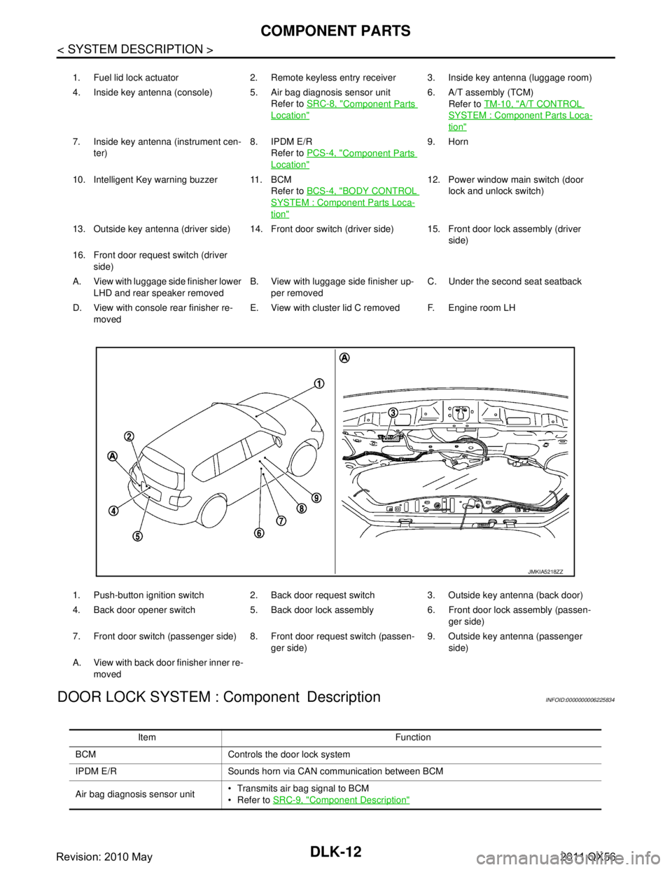
JMKIA5217ZZ
Revision: 2010 May2011 QX56
Page 1548 of 5598

DLK-12
< SYSTEM DESCRIPTION >
COMPONENT PARTS
DOOR LOCK SYSTEM : Component Description
INFOID:0000000006225834
1. Fuel lid lock actuator 2. Remote keyless entry receiver 3. Inside key antenna (luggage room)
4. Inside key antenna (console) 5. Air bag diagnosis sensor unit Refer to SRC-8, "
Component Parts
Location"
6. A/T assembly (TCM)
Refer to TM-10, "
A/T CONTROL
SYSTEM : Component Parts Loca-
tion"
7. Inside key antenna (instrument cen-
ter) 8. IPDM E/R
Refer to PCS-4, "
Component Parts
Location"
9. Horn
10. Intelligent Key warning buzzer 11. BCM Refer to BCS-4, "
BODY CONTROL
SYSTEM : Component Parts Loca-
tion"
12. Power window main switch (door
lock and unlock switch)
13. Outside key antenna (driver side) 14. Front door switch (driver side) 15. Front door lock assembly (driver side)
16. Front door request switch (driver side)
A. View with luggage side finisher lower LHD and rear speaker removed B. View with luggage side finisher up-
per removed C. Under the second seat seatback
D. View with console rear finisher re- moved E. View with cluster lid C removed F. Engine room LH
1. Push-button ignition switch 2. Back door request switch 3. Outside key antenna (back door)
4. Back door opener switch 5. Back door lock assembly 6. Front door lock assembly (passen- ger side)
7. Front door switch (passenger side) 8. Front door request switch (passen- ger side)9. Outside key antenna (passenger
side)
A. View with back door finisher inner re- moved
JMKIA5218ZZ
Item Function
BCM Controls the door lock system
IPDM E/R Sounds horn via CAN communication between BCM
Air bag diagnosis sensor unit Transmits air bag signal to BCM
Refer to
SRC-9, "
Component Description"
Revision: 2010 May2011 QX56
Page 1549 of 5598

COMPONENT PARTSDLK-13
< SYSTEM DESCRIPTION >
C
DE
F
G H
I
J
L
M A
B
DLK
N
O P
AUTOMATIC BACK DOOR SYSTEM
Combination meter Displays each operation method guide and warning for system malfunction
Performs operation method guide and warning with buzzer
Transmits vehicle speed signal to CAN communication line
TCM Transmits shift position signal to BCM via CAN communication line
Remote keyless entry receiver Receives Intelligent Key operation and transmits to BCM
Inside key antenna Detects if Intelligent Key is inside the vehicle
Outside key antenna Detects if Intelligent Key is outside the vehicle
Push-button ignition switch Inputs push-button ignition switch ON/OFF condition to BCM
Door switch Inputs door open/close condition to BCM
Door lock and unlock switch Detects if door lock and unlock switch is press/release
Integrated in the power window main switch and front power window switch (passenger
side)
Door request switch Detects if each door request switch is press/release
Integrated in the outside handle (driver side, passenger side) and back door opener
switch assembly
Intelligent Key warning buzzer Warns the user of the lock/unlock condition and inappropriate operations with the buzzer
sound
Intelligent Key The following functions are available when having and carrying electronic ID
Door lock/unlock
Engine start
Remote control entry function is available when operating on button
Hazard warning lamp Warns the user of the lock/unlock condition and inappropriate operations with the lamps
blink
Door lock actuator Output lock/unlock signal from BCM and locks/unlocks each door
Fuel lid lock actuator Output lock/unlock signal from BCM and locks/unlocks fuel filler lid Item Function
Revision: 2010 May2011 QX56
Page 1550 of 5598

DLK-14
< SYSTEM DESCRIPTION >
COMPONENT PARTS
AUTOMATIC BACK DOOR SYSTEM : Component Parts Location
INFOID:0000000006225835
1. Combination meter 2. BCM
Refer to BCS-4, "
BODY CONTROL
SYSTEM : Component Parts Loca-
tion"
3. ABS actuator and electric unit
Refer to BRC-10, "
Component Parts
Location"
4. Automatic back door switch 5. Automatic back door main switch 6. Automatic back door control module
JMKIA5223ZZ
Revision: 2010 May2011 QX56
Page 1551 of 5598

COMPONENT PARTSDLK-15
< SYSTEM DESCRIPTION >
C
DE
F
G H
I
J
L
M A
B
DLK
N
O P
AUTOMATIC BACK DOOR SYST EM : Component DescriptionINFOID:0000000006225836
7. Touch sensor LH 8. Back door request switch 9. Back door lock assembly
10. Back door opener switch 11. Automatic back door close switch 12. Automatic back door warning buzzer
13. Touch sensor RH
A. View with luggage side finisher up-
per removed B. View with back door finisher inner re-
moved
Item Function
Automatic back door control mod-
ule Automatic back door control unit, encoder, automatic back door motor and clutch are in-
stalled
Automatic back door control unit: Controls the automatic back door system
Encoder: Automatic back door control unit receives the pulse signals from encoders A
and B that occurred due to synchronization with the back door operation. The automatic
back door control unit calculates the back door position, operation direction, and opera-
tion speed according to the received pulse signals.
Automatic back door motor: Inputs open/close signal from automatic back door control
unit and activates the automatic back door open/close operation.
Clutch: Performs the duty control of the power supply to control the operation speed of the back door.
BCM Transmits and receives signals to the automatic back door control module
ABS actuator and electric unit Transmits vehi cle speed signal to CAN communication line
Combination meter Transmits vehicle speed signal to CAN communication line
Automatic back door warning buzz-
er Warns the user of the automatic back door condition and inappropriate operations with the
buzzer sounds
Touch sensor LH/RH During back door close operation, the touch sensor detects any trapped foreign material
Back door opener switch Detects if back door opener switch is press/release
Back door request switch Detects if back door request switch is press/release
Automatic back door switch Detects if automatic back door switch is press/release
Automatic back door main switch Detects if automatic back door main switch is press/release
Automatic back door close switch Detects if automatic back door close switch is press/release
Back door lock assembly Back door closure motor, half latch switch, open switch, close switch and back door switch
are installed
Closure motor: Inputs open/close signal from automatic back door control unit and acti-
vates the back door auto closure operation
Half latch switch: Starts the closure motor close operation
Open switch: Stops the closure motor open operation
Close switch: Stops the closure motor close operation
Back door switch: Inputs back door open/ close condition to BCM
Revision: 2010 May2011 QX56