sensor INFINITI QX56 2011 Factory Service Manual
[x] Cancel search | Manufacturer: INFINITI, Model Year: 2011, Model line: QX56, Model: INFINITI QX56 2011Pages: 5598, PDF Size: 94.53 MB
Page 5027 of 5598

ST-40
< REMOVAL AND INSTALLATION >
STEERING SHAFT
Rotate the steering shaft to check runout of the steering shaft atthe runout measuring point ( ) by using dial indicator and V-block.
Check each part of steering shaft for damage and other malfunc- tions. Replace if there is a malfunction.
INSPECTION AFTER INSTALLATION
Check dust boot bellows (deformation, such as dent s). Manually rework the bellows, as necessary.
Check if steering wheel turns smoothly when it is tur ned several times fully to the end of the left and right.
Check the steering wheel play, neutral position steeri ng wheel, steering wheel turning force, and front wheel
turning angle. Refer to ST-32, "
Inspection".
Adjust neutral position of steering angle sensor. Refer to BRC-64, "
Work Procedure".
Runout : Refer to
ST-58, "
Steering Shaft Sliding
Range".
A : 120 mm (4.72 in)
B : 240 mm (9.45 in)
JPGIA0075ZZ
Revision: 2010 May2011 QX56
Page 5034 of 5598
STEERING GEAR AND LINKAGEST-47
< REMOVAL AND INSTALLATION >
C
DE
F
H I
J
K L
M A
B
ST
N
O P
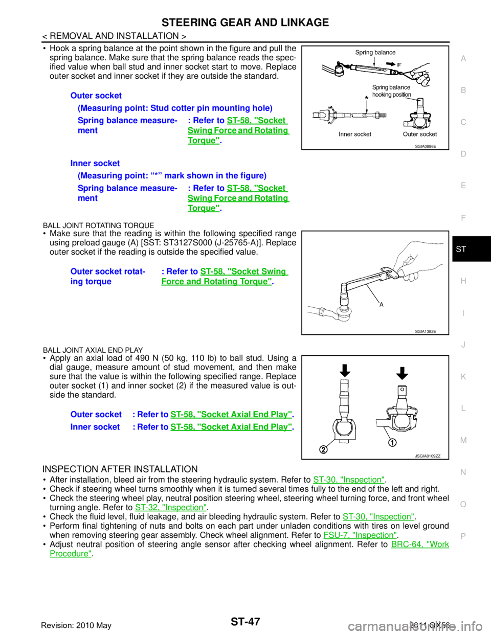
Hook a spring balance at the point shown in the figure and pull the spring balance. Make sure that the spring balance reads the spec-
ified value when ball stud and inner socket start to move. Replace
outer socket and inner socket if they are outside the standard.
BALL JOINT ROTATING TORQUE
Make sure that the reading is within the following specified rangeusing preload gauge (A) [SST: ST3127S000 (J-25765-A)]. Replace
outer socket if the reading is outside the specified value.
BALL JOINT AXIAL END PLAY
Apply an axial load of 490 N (50 kg, 110 lb) to ball stud. Using adial gauge, measure amount of stud movement, and then make
sure that the value is within the following specified range. Replace
outer socket (1) and inner socket (2) if the measured value is out-
side the standard.
INSPECTION AFTER INSTALLATION
After installation, bleed air from the steering hydraulic system. Refer to ST-30, "Inspection".
Check if steering wheel turns smoothly when it is turned several times fully to the end of the left and right.
Check the steering wheel play, neutral position steeri ng wheel, steering wheel turning force, and front wheel
turning angle. Refer to ST-32, "
Inspection".
Check the fluid level, fluid leakage, and air bleeding hydraulic system. Refer to ST-30, "
Inspection".
Perform final tightening of nuts and bolts on each part under unladen conditions with tires on level ground when removing steering gear assembly. Check wheel alignment. Refer to FSU-7, "
Inspection".
Adjust neutral position of steering angle sensor after checking wheel alignment. Refer to BRC-64, "
Work
Procedure".
Outer socket
(Measuring point: Stud cotter pin mounting hole)
Spring balance measure-
ment : Refer to
ST-58, "
Socket
Swing Force and Rotating
To r q u e".
Inner socket (Measuring point: “*” mark shown in the figure)
Spring balance measure-
ment : Refer to
ST-58, "
Socket
Swing Force and Rotating
To r q u e".
Outer socket rotat-
ing torque : Refer to
ST-58, "
Socket Swing
Force and Rotating Torque".
SGIA0896E
SGIA1382E
Outer socket : Refer to ST-58, "Socket Axial End Play".
Inner socket : Refer to ST-58, "
Socket Axial End Play".
JSGIA0109ZZ
Revision: 2010 May2011 QX56
Page 5037 of 5598
ST-50
< REMOVAL AND INSTALLATION >
POWER STEERING OIL PUMP
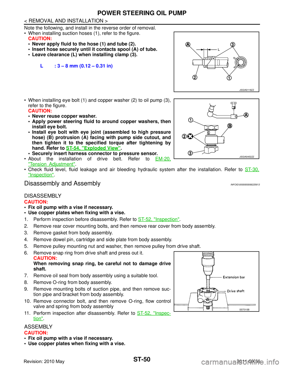
Note the following, and install in the reverse order of removal.
When installing suction hoses (1), refer to the figure.CAUTION:
Never apply fluid to the hose (1) and tube (2).
Insert hose securely until it contacts spool (A) of tube.
Leave clearance (L) when installing clamp (3).
When installing eye bolt (1) and copper washer (2) to oil pump (3), refer to the figure.
CAUTION:
Never reuse copper washer.
Apply power steering fluid to around copper washers, then
install eye bolt.
Install eye bolt with eye join t (assembled to high pressure
hose) (B) protrusion (A) facing with pump side cutout, and
then tighten it to the specifi ed torque after tightening by
hand. Refer to ST-54, "
Exploded View".
Securely insert harness connector to pressure sensor.
About the installation of drive belt. Refer to EM-20,
"TensionAdjustment".
Check fluid level, fluid leakage and air bleeding hydr aulic system after the installation. Refer to ST-30,
"Inspection".
Disassembly and AssemblyINFOID:0000000006225613
DISASSEMBLY
CAUTION:
Fix oil pump with a vise if necessary.
Use copper plates when fixing with a vise.
1. Perform inspection before disassembly. Refer to ST-52, "
Inspection".
2. Remove rear cover mounting bolts, and then remove rear cover from body assembly.
3. Remove gasket from body assembly.
4. Remove dowel pin, cartridge and side plate from body assembly.
5. Remove pulley mounting nut and washer, then remove pulley from drive shaft.
6. Remove snap ring from drive shaft and press out it. CAUTION:
When removing snap ring, be careful not to damage drive
shaft.
7. Remove oil seal from body assembly using a suitable tool.
8. Remove O-ring from body assembly.
9. Remove mounting bolts of suction pipe, and then remove suc- tion pipe and bracket from body assembly.
10. Remove connector bolt, and then remove O-ring, flow control
valve and spring from body assembly
11. Perform inspection after disassembly. Refer to ST-52, "
Inspec-
tion".
ASSEMBLY
CAUTION:
Fix oil pump with a vise if necessary.
Use copper plates when fixing with a vise.L : 3 – 8 mm (0.12 – 0.31 in)
JSGIA0118ZZ
JSGIA0452ZZ
SST010B
Revision: 2010 May2011 QX56
Page 5040 of 5598
![INFINITI QX56 2011 Factory Service Manual
POWER STEERING OIL PUMPST-53
< REMOVAL AND INSTALLATION >
C
DE
F
H I
J
K L
M A
B
ST
N
O P
1. Connect the oil pressure gauge [SST: KV48103500 (J-26357)] and the oil pressure gauge adapter [SST: KV4810 INFINITI QX56 2011 Factory Service Manual
POWER STEERING OIL PUMPST-53
< REMOVAL AND INSTALLATION >
C
DE
F
H I
J
K L
M A
B
ST
N
O P
1. Connect the oil pressure gauge [SST: KV48103500 (J-26357)] and the oil pressure gauge adapter [SST: KV4810](/img/42/57033/w960_57033-5039.png)
POWER STEERING OIL PUMPST-53
< REMOVAL AND INSTALLATION >
C
DE
F
H I
J
K L
M A
B
ST
N
O P
1. Connect the oil pressure gauge [SST: KV48103500 (J-26357)] and the oil pressure gauge adapter [SST: KV48102500 (J-
33914)] between oil pump discharge connector and high-pres-
sure hose. Bleed air from the hydraulic circuit while opening
valve fully. Refer to ST-30, "
Inspection".
2. Start engine. Run engine until oil temperature reaches 50 to 80°C (122 to 176 °F).
CAUTION:
Leave the valve of the oil pressure gauge fully open while
starting and running engine. If engine is started with the
valve closed, the hydraulic pressure in oil pump goes up
to the relief pressure along with unusual increase of oil
temperature.
Be sure to keep hose clear of belts and other parts when engine is started.
3. Fully close the oil pressure gauge valve with engine at idle and measure the relief oil pressure.
CAUTION:
Never keep valve closed for 10 seconds or longer.
4. Open the valve slowly after measuring. Repair oil pump if the relief oil pressure is outside the standard. Refer to ST-50, "
Disassembly and Assembly".
5. Disconnect the oil pressure gauge from hydraulic circuit.
6. When installing eye bolt (1) and copper washer (2) to oil pump (3), refer to the figure.
CAUTION:
Never reuse copper washers.
Apply power steering fluid to around copper washer, theninstall eye bolt.
Install eye bolt with eye join t (assembled to high pressure
hose) (B) protrusion (A) facing with pump side cutout, and
then tighten it to the specifi ed torque after tightening by
hand. Refer to ST-54, "
Exploded View".
Securely insert harness connector to pressure sensor.
7. Check fluid level, fluid leakage and air bleeding hydraulic sys- tem after the installation. Refer to ST-30, "
Inspection".
Relief oil pressure : Refer to
ST-58, "
Relief Oil Pres-
sure".
SGIA1225E
JSGIA0452ZZ
Revision: 2010 May2011 QX56
Page 5041 of 5598

ST-54
< REMOVAL AND INSTALLATION >
HYDRAULIC LINE
HYDRAULIC LINE
Exploded ViewINFOID:0000000006225615
Engine speed sensitive type
JPGIA0096GB
1. Reservoir tank bracket 2. Reservoir tank 3. Clamp
4. Suction hose 5. Return hose 6. Eye bolt
7. Copper washer 8. Pressure sensor 9. Oil cooler
10. High pressure piping 11. Low pressure piping 12. Steering gear assembly
A. To power steering oil pump suction hose.
B. To power steering oil pump.
Refer to GI-4, "
Components" for symbols in the figure.
Revision: 2010 May2011 QX56
Page 5042 of 5598

HYDRAULIC LINEST-55
< REMOVAL AND INSTALLATION >
C
DE
F
H I
J
K L
M A
B
ST
N
O P
Vehicle speed sensitive type
JPGIA0074GB
1. Reservoir tank bracket 2. Reservoir tank 3. Clamp
4. Suction hose 5. Return hose 6. Eye bolt
7. Copper washer 8. Pressure sensor 9. Oil cooler
10. High pressure piping 11. Low pressure piping 12. Steering gear assembly
A. To power steering oil pump suction hose.
B. To power steering oil pump.
Refer to GI-4, "
Components" for symbols in the figure.
Revision: 2010 May2011 QX56
Page 5047 of 5598
STC-2
< PRECAUTION >
PRECAUTIONS
PRECAUTION
PRECAUTIONS
Precaution for Supplemental Restraint System (SRS) "AIR BAG" and "SEAT BELT
PRE-TENSIONER"
INFOID:0000000006303358
The Supplemental Restraint System such as “A IR BAG” and “SEAT BELT PRE-TENSIONER”, used along
with a front seat belt, helps to reduce the risk or severi ty of injury to the driver and front passenger for certain
types of collision. This system includes seat belt switch inputs and dual stage front air bag modules. The SRS
system uses the seat belt switches to determine the front air bag deployment, and may only deploy one front
air bag, depending on the severity of a collision and w hether the front occupants are belted or unbelted.
Information necessary to service the system safely is included in the “SRS AIR BAG” and “SEAT BELT” of this
Service Manual.
WARNING:
• To avoid rendering the SRS inopera tive, which could increase the risk of personal injury or death in
the event of a collision that would result in air bag inflation, all maintenance must be performed by
an authorized NISS AN/INFINITI dealer.
Improper maintenance, including in correct removal and installation of the SRS, can lead to personal
injury caused by unintent ional activation of the system. For re moval of Spiral Cable and Air Bag
Module, see the “SRS AIR BAG”.
Do not use electrical test equipmen t on any circuit related to the SRS unless instructed to in this
Service Manual. SRS wiring harnesses can be identi fied by yellow and/or orange harnesses or har-
ness connectors.
PRECAUTIONS WHEN USING POWER TOOLS (AIR OR ELECTRIC) AND HAMMERS
WARNING:
When working near the Air Bag Diagnosis Sensor Unit or other Air Bag System sensors with the ignition ON or engine running, DO NOT use air or electric power tools or strike near the sensor(s)
with a hammer. Heavy vibration could activate the sensor(s) and deploy the air bag(s), possibly
causing serious injury.
When using air or electric power tools or hammers , always switch the ignition OFF, disconnect the
battery, and wait at least 3 minu tes before performing any service.
Precaution Necessary for Steering W heel Rotation after Battery Disconnect
INFOID:0000000006303360
NOTE:
Before removing and installing any control units, first tu rn the push-button ignition switch to the LOCK posi-
tion, then disconnect bot h battery cables.
After finishing work, confirm that all control unit connectors are connected properly, then re-connect both
battery cables.
Always use CONSULT-III to perform self-diagnosis as a part of each function inspection after finishing work.
If a DTC is detected, perform trouble diagnos is according to self-diagnosis results.
For vehicle with steering lock unit, if the battery is disconnected or discharged, the steering wheel will lock and
cannot be turned.
If turning the steering wheel is required with the bat tery disconnected or discharged, follow the operation pro-
cedure below before starting the repair operation.
OPERATION PROCEDURE
1. Connect both battery cables. NOTE:
Supply power using jumper cables if battery is discharged.
2. Turn the push-button ignition switch to ACC position. (At this time, the steering lock will be released.)
3. Disconnect both battery cables. The steering lock wi ll remain released with both battery cables discon-
nected and the steering wheel can be turned.
4. Perform the necessary repair operation.
Revision: 2010 May2011 QX56
Page 5049 of 5598

STC-4
< SYSTEM DESCRIPTION >
COMPONENT PARTS
SYSTEM DESCRIPTION
COMPONENT PARTS
Component Parts LocationINFOID:0000000006256115
Component DescriptionINFOID:0000000006256116
Power Steering Control UnitINFOID:0000000006256117
Signals from various sensors control the driving voltage to the power steering solenoid valve.
The power steering control unit controls the driving vo ltage to the power steering solenoid valve for maintain-
ing the power steering assist force when the fail-safe function is activated. (The engine speed signals control
EPS system if any vehicle s peed signal error is detected.)
Power Steering Solenoid ValveINFOID:0000000006256118
Power steering solenoid valve controls the power steering oil pressure in the gear housing assembly.
1. ECM
Refer to EC-16, "
Component Parts
Location". 2. Combination meter
Refer to MWI-6, "
METER SYSTEM :
Component Parts Location". 3. Power steering control unit
4. Power steering solenoid valve
A. Glove box assembly removed B. Steering gear assembly
JPGIB0006ZZ
Component parts Reference/Function
Power steering control unit STC-4, "
Power Steering Control Unit"
Power steering solenoid valveSTC-4, "Power Steering Solenoid Valve"
Combination meter Transmits vehicle speed signal to power steering control unit.
ECM Transmits engine speed signal to power steering control unit.
Revision: 2010 May2011 QX56
Page 5070 of 5598
STR-2
< PRECAUTION >
PRECAUTIONS
PRECAUTION
PRECAUTIONS
Precaution for Supplemental Restraint System (SRS) "AIR BAG" and "SEAT BELT
PRE-TENSIONER"
INFOID:0000000006275515
The Supplemental Restraint System such as “A IR BAG” and “SEAT BELT PRE-TENSIONER”, used along
with a front seat belt, helps to reduce the risk or severi ty of injury to the driver and front passenger for certain
types of collision. This system includes seat belt switch inputs and dual stage front air bag modules. The SRS
system uses the seat belt switches to determine the front air bag deployment, and may only deploy one front
air bag, depending on the severity of a collision and w hether the front occupants are belted or unbelted.
Information necessary to service the system safely is included in the “SRS AIR BAG” and “SEAT BELT” of this
Service Manual.
WARNING:
• To avoid rendering the SRS inopera tive, which could increase the risk of personal injury or death in
the event of a collision that would result in air bag inflation, all maintenance must be performed by
an authorized NISS AN/INFINITI dealer.
Improper maintenance, including in correct removal and installation of the SRS, can lead to personal
injury caused by unintent ional activation of the system. For re moval of Spiral Cable and Air Bag
Module, see the “SRS AIR BAG”.
Do not use electrical test equipmen t on any circuit related to the SRS unless instructed to in this
Service Manual. SRS wiring harnesses can be identi fied by yellow and/or orange harnesses or har-
ness connectors.
PRECAUTIONS WHEN USING POWER TOOLS (AIR OR ELECTRIC) AND HAMMERS
WARNING:
When working near the Air Bag Diagnosis Sensor Unit or other Air Bag System sensors with the ignition ON or engine running, DO NOT use air or electric power tools or strike near the sensor(s)
with a hammer. Heavy vibration could activate the sensor(s) and deploy the air bag(s), possibly
causing serious injury.
When using air or electric power tools or hammers , always switch the ignition OFF, disconnect the
battery, and wait at least 3 minu tes before performing any service.
Precaution Necessary for Steering W heel Rotation after Battery Disconnect
INFOID:0000000006275516
NOTE:
Before removing and installing any control units, first tu rn the push-button ignition switch to the LOCK posi-
tion, then disconnect bot h battery cables.
After finishing work, confirm that all control unit connectors are connected properly, then re-connect both
battery cables.
Always use CONSULT-III to perform self-diagnosis as a part of each function inspection after finishing work.
If a DTC is detected, perform trouble diagnos is according to self-diagnosis results.
For vehicle with steering lock unit, if the battery is disconnected or discharged, the steering wheel will lock and
cannot be turned.
If turning the steering wheel is required with the bat tery disconnected or discharged, follow the operation pro-
cedure below before starting the repair operation.
OPERATION PROCEDURE
1. Connect both battery cables. NOTE:
Supply power using jumper cables if battery is discharged.
2. Turn the push-button ignition switch to ACC position. (At this time, the steering lock will be released.)
3. Disconnect both battery cables. The steering lock wi ll remain released with both battery cables discon-
nected and the steering wheel can be turned.
4. Perform the necessary repair operation.
Revision: 2010 May2011 QX56
Page 5089 of 5598
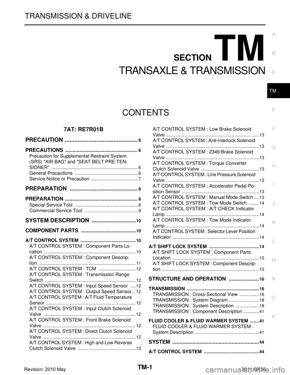
TM-1
TRANSMISSION & DRIVELINE
CEF
G H
I
J
K L
M
SECTION TM
A
B
TM
N
O P
CONTENTS
TRANSAXLE & TRANSMISSION
7AT: RE7R01B
PRECAUTION ................ ...............................
6
PRECAUTIONS .............................................. .....6
Precaution for Supplemental Restraint System
(SRS) "AIR BAG" and "SEAT BELT PRE-TEN-
SIONER" ............................................................. ......
6
General Precautions .................................................6
Service Notice or Precaution .....................................7
PREPARATION ............................................8
PREPARATION .............................................. .....8
Special Service Tool ........................................... ......8
Commercial Service Tool ..........................................9
SYSTEM DESCRIPTION .............................10
COMPONENT PARTS ................................... ....10
A/T CONTROL SYSTEM ...........................................10
A/T CONTROL SYSTEM : Component Parts Lo-
cation ................................................................... ....
10
A/T CONTROL SYSTEM : Component Descrip-
tion ...................................................................... ....
11
A/T CONTROL SYSTEM : TCM .............................12
A/T CONTROL SYSTEM : Transmission Range
Switch .................................................................. ....
12
A/T CONTROL SYSTEM : Input Speed Sensor .....12
A/T CONTROL SYSTEM : Output Speed Sensor ....12
A/T CONTROL SYSTEM : A/ T Fluid Temperature
Sensor ................................................................. ....
12
A/T CONTROL SYSTEM : Input Clutch Solenoid
Valve ................................................................... ....
12
A/T CONTROL SYSTEM : Front Brake Solenoid
Valve ................................................................... ....
12
A/T CONTROL SYSTEM : Direct Clutch Solenoid
Valve ................................................................... ....
12
A/T CONTROL SYSTEM : High and Low Reverse
Clutch Solenoid Valve ......................................... ....
13
A/T CONTROL SYSTEM : Low Brake Solenoid
Valve .................................................................... ....
13
A/T CONTROL SYSTEM : Anti-interlock Solenoid
Valve ........................................................................
13
A/T CONTROL SYSTEM : 2346 Brake Solenoid
Valve ........................................................................
13
A/T CONTROL SYSTEM : Torque Converter
Clutch Solenoid Valve ......................................... ....
13
A/T CONTROL SYSTEM : Line Pressure Solenoid
Valve .................................................................... ....
13
A/T CONTROL SYSTEM : Accelerator Pedal Po-
sition Sensor ........................................................ ....
13
A/T CONTROL SYSTEM : Manual Mode Switch ....13
A/T CONTROL SYSTEM : To w Mode Switch .........14
A/T CONTROL SYSTEM : A/T CHECK Indicator
Lamp .................................................................... ....
14
A/T CONTROL SYSTEM : Tow Mode Indicator
Lamp .................................................................... ....
14
A/T CONTROL SYSTEM : Selector Lever Position
Indicator ............................................................... ....
14
A/T SHIFT LOCK SYSTEM ................................... ....14
A/T SHIFT LOCK SYSTEM : Component Parts
Location ...................................................................
15
A/T SHIFT LOCK SYSTEM : Component Descrip-
tion ...........................................................................
15
STRUCTURE AND OPERATION .....................16
TRANSMISSION .................................................... ....16
TRANSMISSION : Cross-Sectional View ................16
TRANSMISSION : System Diagram ........................18
TRANSMISSION : System Description ...................18
TRANSMISSION : Component Description .............41
FLUID COOLER & FLUID WARMER SYSTEM .... ....41
FLUID COOLER & FLUID WARMER SYSTEM :
System Description ..................................................
41
SYSTEM ............................................................44
A/T CONTROL SYSTEM ....................................... ....44
Revision: 2010 May2011 QX56