radiator INFINITI QX56 2011 Factory Service Manual
[x] Cancel search | Manufacturer: INFINITI, Model Year: 2011, Model line: QX56, Model: INFINITI QX56 2011Pages: 5598, PDF Size: 94.53 MB
Page 676 of 5598

BRM-1
BODY EXTERIOR, DOORS, ROOF & VEHICLE SECURITY
C
D
E
F
G H
I
J
L
M
SECTION BRM
A
B
BRM
N
O P
CONTENTS
BODY REPAIR
VEHICLE INFORMATION ... ..........................2
BODY EXTERIOR PAINT COLOR ................ .....2
Body Exterior Paint Color ................................. ......2
PRECAUTION ...............................................4
REPAIRING HIGH STRENGTH STEEL ......... .....4
High Strength Steel (HSS) ................................ ......4
Handling of Ultra High Strength Steel Plate Parts ......6
PREPARATION ............................................7
REPAIRING MATERIAL ................................ .....7
Foam Repair ....................................................... ......7
BODY COMPONENT PARTS .............................9
Underbody Component Parts ............................ ......9
Body Component Parts ...........................................11
Frame Component Parts .........................................13
REMOVAL AND INSTALLATION ...............15
CORROSION PROTECTION ......................... ....15
Description .......................................................... ....15
Anti-corrosive Wax ..................................................15
Undercoating ...........................................................16
Stone Guard Coat ...................................................17
Body Sealing ...........................................................18
BODY CONSTRUCTION ....................................22
Body Construction ............................................... ....22
REPLACEMENT OPERATIONS .......................24
Description ...............................................................24
Radiator Core Support .............................................26
Hoodledge ...............................................................26
Hoodledge (Partial Replacement) ...........................27
Front Pillar ...............................................................29
Center Pillar .............................................................32
Outer Sill .................................................................35
Rear Fender ............................................................39
Rear Fender Extension ............................................42
Rear Panel and Rear End Crossmember ................42
Rear Floor Rear .....................................................45
Crush Horn ..............................................................46
SERVICE DATA AND SPECIFICATIONS
(SDS) ............... .............................................
48
BODY ALIGNMENT ..........................................48
Body Center Marks ............................................ ....48
Description ...............................................................48
Engine Compartment ..............................................49
Underbody ...............................................................52
Passenger Compartment .........................................54
Rear Body ...............................................................56
LOCATION OF PLASTIC PARTS ....................58
Precautions for Plastics ...........................................58
Location of Plastic Parts ..........................................59
Revision: 2010 May2011 QX56
Page 679 of 5598

BRM-4
< PRECAUTION >
REPAIRING HIGH STRENGTH STEEL
PRECAUTION
REPAIRING HIGH STRENGTH STEEL
High Strength Steel (HSS)INFOID:0000000006248484
High strength steel is used for body panels in order to reduce vehicle weight.
Accordingly, precautions in repairing automotive bodies made of high strength steel are described below:
Read the following precautions when repairing HSS:
1. Additional points to consider
Tensile strength Major applicable parts 440 - 780 MPa Rear floor reinforcement
2nd seat mounting member assembly
Front seat mounting rear crossmember assembly
Front floor reinforcement
2nd crossmember (Lower)
Side radiator core support
Radiator core support main assembly
Front side member assembly
4th crossmember
2nd seat mounting crossmember
Rear side member
Rear crossmember
Inner side roof rail
Upper inner front pillar
Inner center pillar
Upper front pillar reinforcement
Lower center pillar brace
Front pillar brace
Outer sill reinforcement
Front roof rail
Rear roof rail
Radiator guard crossmember assembly
2nd crossmember assembly
2nd crossmember reinforcement
Front side member assembly
Front bound bumper bracket assembly
Lower front link mounting bracket assembly
Center side member assembly
Fuel tank protector assembly
Rear suspension mounting bracket assembly
Rear shock absorber bracket assembly
Rear side member assembly
Rear end gusset
Rear end crossmember assembly
980 - 1350 MPa Lower dash center reinforcement
(Lower dash Component part)
Inner sill
Rear seat crossmember
(2nd seat mounting crossmember component part)
Inner center pillar (Upper)
Upper outer center pillar reinforcement
(Lower center pillar brace component part)
Front bumper crossmember assembly
Revision: 2010 May2011 QX56
Page 685 of 5598

BRM-10
< PREPARATION >
BODY COMPONENT PARTS
NOTE:
For the parts without a number described in the figure, it is supplied only with the assembly part that the part is included with.
Tensile strength column shows the largest strength value of a part in the component part.
CAUTION:
If the high strength steel (ultra high strength steel) of this is broken, replace by assembly for the supply part. No. Parts name
Tensile strength
(MPa) Both sided anti-corrosive
precoated steel sections
1. Air box assembly Under 440 ×
2. Side dash (RH & LH) Under 440 ×
3. Lower dash a. T=2.0 mm
(0.079 in)
980
caution×
4. Trim mounting bracket assembly Under 440 —
5. Rear floor board reinforcement assembly Under 440 —
6. Jack mounting bracket Under 440 —
7. Rear floor rear Under 440 ×
8. 3rd seat front mounting bracket assembly Under 440 —
9. Rear floor reinforcement 440 —
10. Inner rear wheelhouse reinforcement (RH & LH) Under 440 ×
11. Rear floor front Under 440 ×
12. 2nd seat crossmember front reinforcement Under 440 ×
13. 2nd seat mounting member assembly 440 —
14. 2nd crossmember (RH & LH Upper) Under 440 —
15. Front seat mounting rear crossmember assembly 440 ×
16. Inner sill (RH & LH) T=1.4 mm
(0.055 in)
980
caution×
17. Front floor reinforcement 440 —
18. Front floor Under 440 ×
19. 2nd crossmember (RH & LH Lower) 440 ×
20. Hoodledge reinforcement (RH & LH) Under 440 ×
21. Hoodledge assembly (RH & LH) Refer to No.22 −24
22. Upper hoodledge (RH & LH) Under 440 ×
23. Lower hoodledge (RH & LH) Under 440 ×
24. Upper rear hoodledge (RH & LH) Under 440 ×
25. Side radiator core support (RH & LH) 440 ×
26. Upper radiator core support (RH & LH) Under 440 ×
27. Radiator core support main assembly 440 ×
28. Front side member assembly (RH & LH) 590 ×
29. 4th crossmember 590 ×
30. 2nd seat mounting crossmember b. T=2.0 mm
(0.079 in)
980
caution×
31. Rear side member (RH & LH) 590 ×
32. 3rd seat mounting bracket assembly Under 440 ×
33. 3rd rear crossmember assembly 590 ×
34. Rear crossmember 590 ×
35. Upper rear end crossmember assembly Under 440 ×
Revision: 2010 May2011 QX56
Page 701 of 5598

BRM-26
< REMOVAL AND INSTALLATION >
REPLACEMENT OPERATIONS
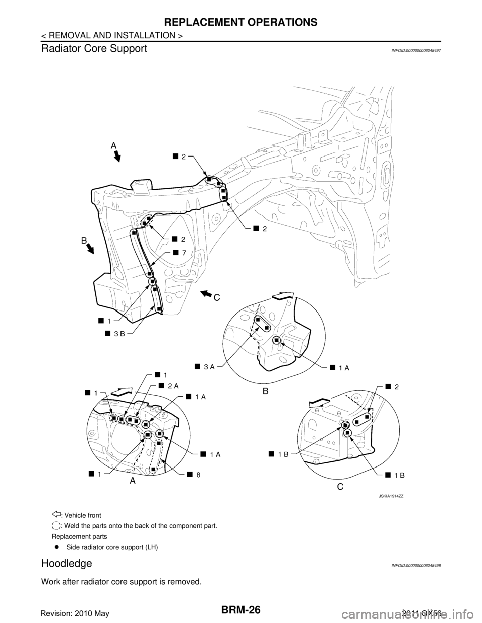
Radiator Core Support
INFOID:0000000006248497
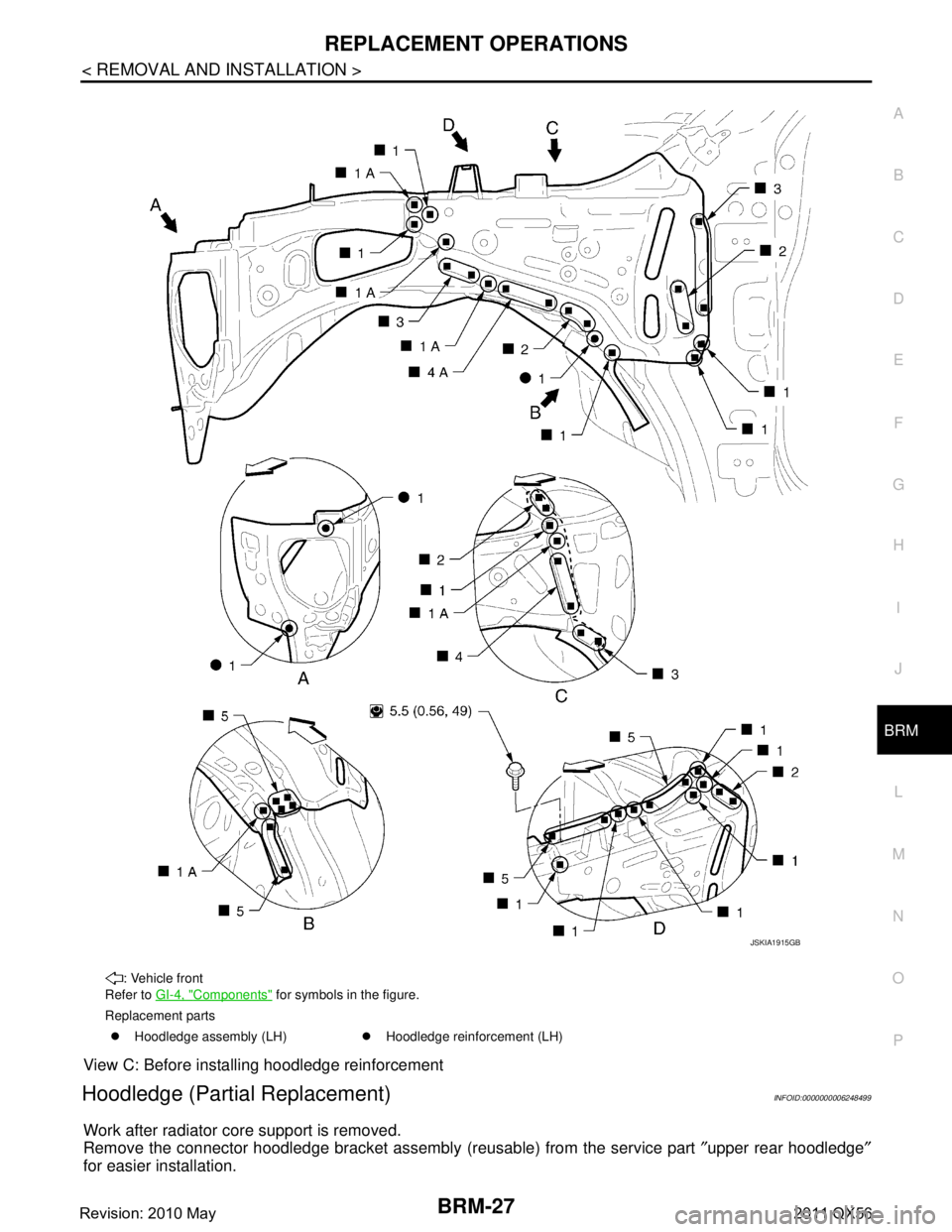
HoodledgeINFOID:0000000006248498
Work after radiator core support is removed.
: Vehicle front
: Weld the parts onto the back of the component part.
Replacement parts �z Side radiator core support (LH)
JSKIA1914ZZ
Revision: 2010 May2011 QX56
Page 702 of 5598

REPLACEMENT OPERATIONSBRM-27
< REMOVAL AND INSTALLATION >
C
DE
F
G H
I
J
L
M A
B
BRM
N
O P
View C: Before installing hoodledge reinforcement
Hoodledge (Partial Replacement)INFOID:0000000006248499
Work after radiator core support is removed.
Remove the connector hoodledge bracket assembly (reusable) from the se\
rvice part ″upper rear hoodledge ″
for easier installation.
: Vehicle front
Refer to GI-4, "
Components" for symbols in the figure.
Replacement parts �z Hoodledge assembly (LH) �zHoodledge reinforcement (LH)
JSKIA1915GB
Revision: 2010 May2011 QX56
Page 726 of 5598

BODY ALIGNMENTBRM-51
< SERVICE DATA AND SPECIFICATIONS (SDS)
C
DE
F
G H
I
J
L
M A
B
BRM
N
O P
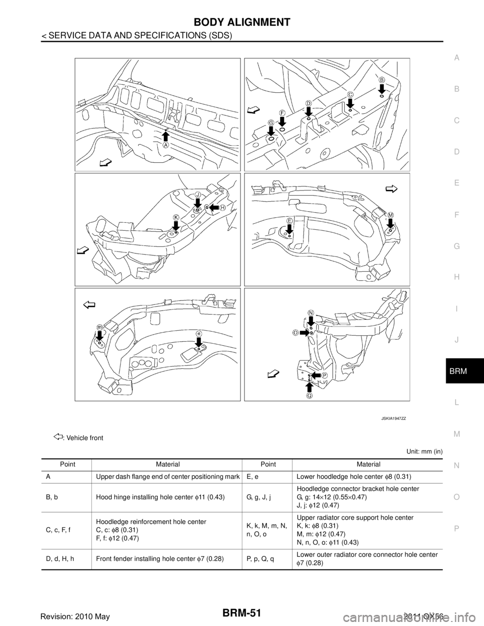
Unit: mm (in)
: Vehicle front
JSKIA1947ZZ
Point Material Point Material
A Upper dash flange end of center positioning mark E, e Lower hoodledge hole center φ8 (0.31)
B, b Hood hinge installing hole center φ11 (0.43) G, g, J, j Hoodledge connector bracket hole center
G, g: 14
×12 (0.55 ×0.47)
J, j: φ12 (0.47)
C, c, F, f Hoodledge reinforcement hole center
C, c:
φ8 (0.31)
F, f: φ12 (0.47) K, k, M, m, N,
n, O, oUpper radiator core support hole center
K, k:
φ8 (0.31)
M, m: φ12 (0.47)
N, n, O, o: φ11 ( 0 . 4 3 )
D, d, H, h Front fender installing hole center φ7 (0.28) P, p, Q, q Lower outer radiator core connector hole center
φ
7 (0.28)
Revision: 2010 May2011 QX56
Page 943 of 5598

CO-1
ENGINE
C
DE
F
G H
I
J
K L
M
SECTION CO
A
CO
N
O P
CONTENTS
ENGINE COOLING SYSTEM
PRECAUTION ................ ...............................2
PRECAUTIONS .............................................. .....2
Precaution for Supplemental Restraint System
(SRS) "AIR BAG" and "SEAT BELT PRE-TEN-
SIONER" ............................................................. ......
2
PREPARATION ............................................3
PREPARATION .............................................. .....3
Commercial Service Tools ................................. ......3
SYSTEM DESCRIPTION ..............................4
DESCRIPTION ............................................... .....4
Engine Cooling System ..................................... ......4
Engine Cooling System Schematic .........................5
SYMPTOM DIAGNOSIS ...............................6
OVERHEATING CAUSE ANALYSIS ............. .....6
Troubleshooting Chart ........................................ ......6
PERIODIC MAINTENANCE ..........................8
ENGINE COOLANT ....................................... .....8
Inspection ............................................................ ......8
Draining .....................................................................8
Refilling .....................................................................9
Flushing ...................................................................10
RADIATOR .........................................................11
RESERVOIR TANK CAP ..........................................11
RESERVOIR TANK CAP : Inspection ................. ....11
RADIATOR ............................................................. ....11
RADIATOR : Inspection ...........................................11
REMOVAL AND INSTALLATION ...............13
RADIATOR ....................................... .................13
Exploded View ..................................................... ....13
Removal and Installation .........................................13
Inspection ................................................................15
COOLING FAN ..................................................16
Exploded View .........................................................16
Removal and Installation .........................................16
Inspection ................................................................17
WATER PUMP ..................................................18
Exploded View .........................................................18
Removal and Installation .........................................18
Inspection ................................................................19
WATER INLET AND THERMOSTAT ASSEM-
BLY ....................................................................
20
Exploded View .........................................................20
Removal and Installation .........................................20
Inspection ................................................................21
SERVICE DATA AND SPECIFICATIONS
(SDS) ............... .............................................
23
SERVICE DATA AND SPECIFICATIONS
(SDS) .................................................................
23
Periodical Maintenance Specification ................ ....23
Radiator ...................................................................23
Thermostat ..............................................................23
Revision: 2010 May2011 QX56
Page 945 of 5598

PREPARATIONCO-3
< PREPARATION >
C
DE
F
G H
I
J
K L
M A
CO
NP
O
PREPARATION
PREPARATION
Commercial Service ToolsINFOID:0000000006289653
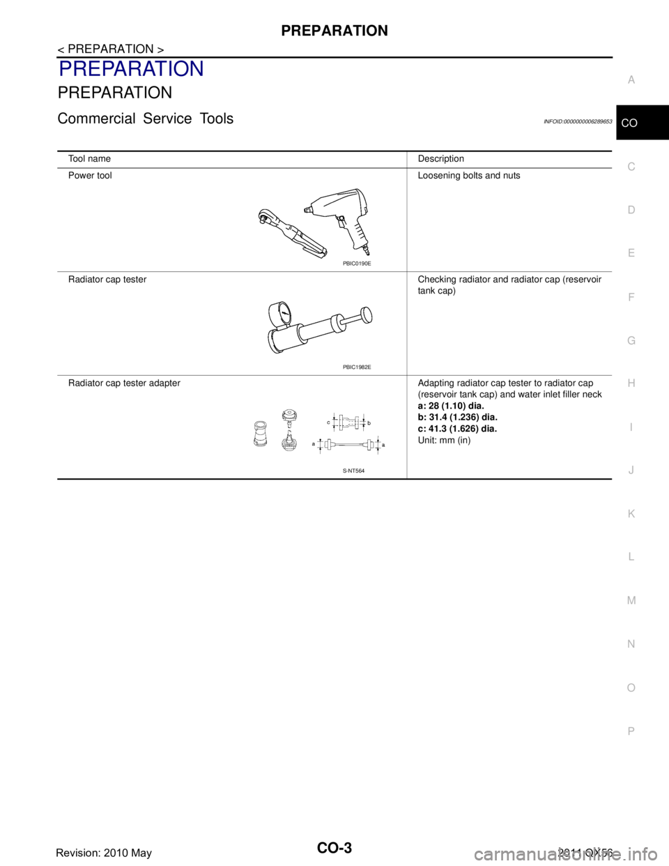
Tool name
Description
Power tool Loosening bolts and nuts
Radiator cap tester Checking radiator and radiator cap (reservoir tank cap)
Radiator cap tester adapter Adapting radiator cap tester to radiator cap (reservoir tank cap) and water inlet filler neck
a: 28 (1.10) dia.
b: 31.4 (1.236) dia.
c: 41.3 (1.626) dia.
Unit: mm (in)
PBIC0190E
PBIC1982E
S-NT564
Revision: 2010 May2011 QX56
Page 948 of 5598

CO-6
< SYMPTOM DIAGNOSIS >
OVERHEATING CAUSE ANALYSIS
SYMPTOM DIAGNOSIS
OVERHEATING CAUSE ANALYSIS
Troubleshooting ChartINFOID:0000000006289656
Symptom Check items
Cooling sys-
tem parts
malfunction Poor heat transfer
Water pump malfunction Worn or loose drive belt
—
Thermostat stuck closed —
Damaged fins
Dust contamination or pa-
per clogging
Physical damage
Clogged radiator cooling
tube Excess foreign material
(rust, dirt, sand, etc.)
Reduced air flow Cooling fan does not oper-
ate
Fan assembly —
High resistance to fan rota-
tion
Damaged fan blades
Damaged radiator shroud — — —
Improper engine coolant
mixture ratio ———
Poor engine coolant quality — Engine coolant density —
Insufficient engine coolant Engine coolant leakageCooling hose
Loose clamp
Cracked hose
Water pump Poor sealing
Radiator cap Loose
Poor sealing
Radiator O-ring for da
mage, deterio-
ration or improper fitting
Cracked radiator tank
Cracked radiator core
Reservoir tank Cracked reservoir tank
Overflowing reservoir tank Exhaust gas leakage into
cooling system Cylinder head deterioration
Cylinder head gasket deteri-
oration
Revision: 2010 May2011 QX56
Page 949 of 5598

OVERHEATING CAUSE ANALYSISCO-7
< SYMPTOM DIAGNOSIS >
C
DE
F
G H
I
J
K L
M A
CO
NP
O
Except cool-
ing system
parts mal-
function — Overload on engine
Abusive driving
High engine rpm under no
load
Driving in low gear for ex-
tended time
Driving at extremely high
speed
Powertrain system malfunc-
tion
—
Installed improper size
wheels and tires
Dragging brakes
Improper ignition timing
Blocked or restricted air
flow Blocked bumper —
—
Blocked radiator grille
Installed car brassiere
Mud contamination or paper
clogging
Blocked radiator —
Blocked condenser Blocked air flow
Installed large fog lamp
Symptom Check items
Revision: 2010 May2011 QX56