stop start INFINITI QX56 2011 Factory Service Manual
[x] Cancel search | Manufacturer: INFINITI, Model Year: 2011, Model line: QX56, Model: INFINITI QX56 2011Pages: 5598, PDF Size: 94.53 MB
Page 2622 of 5598
EM-60
< REMOVAL AND INSTALLATION >
OIL PAN (UPPER)
3. Install oil pan (lower). Refer to EM-55, "Removal and Installation".
4. Install in the reverse order of removal. NOTE:
At least 30 minutes after oil pan is installed, pour engine oil.
InspectionINFOID:0000000006289564
INSPECTION AFTER DISASSEMBLY
Clean oil strainer if any object is attached.
INSPECTION AFTER ASSEMBLY
1. Check the engine oil level and adjust engine oil. Refer to LU-9, "Inspection".
2. Start engine, and check there is no leakage of engine oil.
3. Stop engine and wait for 15 minutes.
4. Check the engine oil level again. Refer to LU-9, "
Inspection".
Revision: 2010 May2011 QX56
Page 2626 of 5598

EM-64
< REMOVAL AND INSTALLATION >
TIMING CHAIN
24. Remove oil pump and oil pump drive spacer.
25. Remove front oil seal from front cover using suitable tool. Use screwdriver for removal.
CAUTION:
Be careful not to damage front cover.
26. Remove O-rings (1), (2), (3) from cylinder heads and cylinder block.
27. Remove oil filter (for valve timing control solenoid valve), if necessary.
28. Remove timing chain tensioner cover from front cover, if necessary. Use seal cutter [SST: KV10111100 (J-37228)] to cut liquid gasket for removal.
29. Remove timing chain tensioner (bank 1) as per the following: NOTE:
To remove timing chain and related parts, start with those on bank 1. The procedure for removing parts on
bank 2 is omitted because it is the same as that for bank 1.
a. Push both sides of spring (A) against spring tension, and then press in plunger with a slack guide (2).
b. Insert a stopper pin (A) into the body hole, and then fix it with the
plunger pushed in.
30. Remove high pressure fuel pump camshaft.
31. Remove tension guide and slack guide.
32. Remove exhaust camshaft sprocket as per the following: Secure the hexagonal portion of exhaust camshaf t using a wrench to loosen mounting bolt.
33. Remove timing chain and crankshaft sprocket. CAUTION:
After removing timing chain, never turn cranksh aft and camshaft separately, or valves will strike
the piston head.
34. Remove intake camshaft sprocket as per the following:
JPBIA3473ZZ
1 : Timing chain tensioner (bank 1)
JPBIA2369ZZ
JPBIA2370ZZ
Revision: 2010 May2011 QX56
Page 2635 of 5598
TIMING CHAINEM-73
< REMOVAL AND INSTALLATION >
C
DE
F
G H
I
J
K L
M A
EM
NP
O
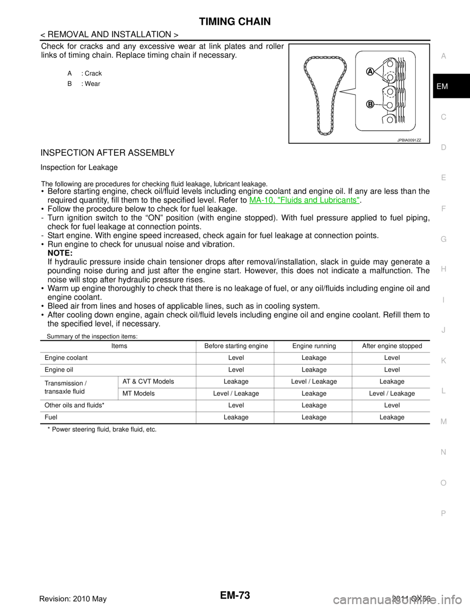
Check for cracks and any excessive
wear at link plates and roller
links of timing chain. Replace timing chain if necessary.
INSPECTION AFTER ASSEMBLY
Inspection for Leakage
The following are procedures for chec king fluid leakage, lubricant leakage. Before starting engine, check oil/fluid levels including engine coolant and engine oil. If any are less than the
required quantity, fill them to the specified level. Refer to MA-10, "
Fluids and Lubricants".
Follow the procedure below to check for fuel leakage.
- Turn ignition switch to the “ON” position (with engi ne stopped). With fuel pressure applied to fuel piping,
check for fuel leakage at connection points.
- Start engine. With engine speed increased, check again for fuel leakage at connection points.
Run engine to check for unusual noise and vibration.
NOTE:
If hydraulic pressure inside chain tensioner drops after removal/installation, slack in guide may generate a
pounding noise during and just after the engine start. However, this does not indicate a malfunction. The
noise will stop after hydraulic pressure rises.
Warm up engine thoroughly to check that there is no leak age of fuel, or any oil/fluids including engine oil and
engine coolant.
Bleed air from lines and hoses of applicable lines, such as in cooling system.
After cooling down engine, again check oil/fluid levels including engine oil and engine coolant. Refill them to the specified level, if necessary.
Summary of the inspection items:
* Power steering fluid, brake fluid, etc. A: Crack
B: Wear
JPBIA0091ZZ
Items Before starting engine Engine running After engine stopped
Engine coolant Level Leakage Level
Engine oil Level Leakage Level
Transmission /
transaxle fluid AT & CVT Models Leakage Level / Leakage Leakage
MT Models Level / Leakage Leakage Level / Leakage
Other oils and fluids* Level Leakage Level
Fuel Leakage Leakage Leakage
Revision: 2010 May2011 QX56
Page 2646 of 5598
EM-84
< REMOVAL AND INSTALLATION >
CAMSHAFT
Move control shaft (A) to the small stopper and large stopper tocheck that the control shaft functions smoothly.
CAUTION:
Turn VVEL ladder assembly upside down to prevent the drive
shaft from dropping off.
RINK CHECK FOR BACK-LASH (BONDING) Check that the link and the shaft of drive shaft and control shaft are
not fixed.
Check this by moving drive shaft and control shaft in the axial and
rotation directions.
If there is an unusualness related to the above three items, replace VVEL ladder assembly & cylinder head
assembly.
NOTE:
VVEL ladder assembly cannot be replaced as a singl e part, because it is machined together with cylinder
head assembly.
INSPECTION AFTER ASSEMBLY
Inspection of Camshaft Sprocket (INT) Oil Groove
CAUTION:
Perform this inspection only when DTC P0011, P 0021 are detected in self-diagnostic results of CON-
SULT-III and it is directed according to inspection procedure of EC section. Refer to EC-177, "
DTC
Logic".
Check when engine is cold to prevent burns from the splashing engine oil.
1. Check engine oil level. Refer to LU-7, "
Inspection".
2. Perform the following procedure to prevent the engine from being unintentionally started while checking.
a. Release the fuel pressure. Refer to EC-153, "
Work Procedure".
b. Disconnect ignition coil and injector harness connectors.
3. Remove valve timing control solenoid valve. Refer to EM-61, "
Exploded View".
4. Crank engine, and then check that engine oil comes out from valve timing control solenoid valve hole (A). End crank after
checking.
WARNING:
Be careful not to touch rotati ng parts (drive belt, idler pul-
ley, and crankshaft pulley, etc.).
CAUTION:
Prevent splashing by using a shop cloth to prevent the worker from injury from en gine oil and to prevent engine
oil contamination.
Prevent splashing by using a shop cloth to prevent engine oil from being splashed to engine and
vehicle. Especially, be careful not to apply engine oil to rubber parts of drive belt, engine mount-
ing insulator, etc. Wipe engine oil out immediately if it is splashed.
: Engine front
JPBIA3521ZZ
JPBIA3522ZZ
1 : Valve timing control cover (bank 2)
JPBIA3523ZZ
Revision: 2010 May2011 QX56
Page 2647 of 5598
CAMSHAFTEM-85
< REMOVAL AND INSTALLATION >
C
DE
F
G H
I
J
K L
M A
EM
NP
O
5. Perform the following inspection if engine oil does not
come out from valve timing control solenoid valve
oil hole of the valve timing control cover.
Remove oil filter, and then clean it. Refer to EM-61, "
Exploded View".
Clean oil groove between oil strainer and valve timing control solenoid valve. Refer to LU-5, "
Engine
Lubrication System" and LU-6, "Engine Lubrication System Schematic".
6. Remove components between valve timing control solenoid valve and camshaft sprocket, and then check each oil groove for clogging.
Clean oil groove if necessary. Refer to LU-5, "
Engine Lubrication System" and LU-6, "Engine Lubrica-
tion System Schematic".
7. After inspection, install removed parts in the reverse order.
Inspection for Leakage
The following are procedures for chec king fluid leakage, lubricant leakage.
Before starting engine, check oil/fluid levels including engine coolant and engine oil. If any are less than the
required quantity, fill them to the specified level. Refer to MA-10, "
Fluids and Lubricants".
Follow the procedure below to check for fuel leakage.
- Turn ignition switch to the “ON” position (with engi ne stopped). With fuel pressure applied to fuel piping,
check for fuel leakage at connection points.
- Start engine. With engine speed increased, check again for fuel leakage at connection points.
Run engine to check for unusual noise and vibration. NOTE:
If hydraulic pressure inside chain tensioner drops after removal/installation, slack in guide may generate a
pounding noise during and just after the engine start. However, this does not indicate a malfunction. The
noise will stop after hydraulic pressure rises.
Warm up engine thoroughly to check that there is no leak age of fuel, or any oil/fluids including engine oil and
engine coolant.
Bleed air from lines and hoses of applicable lines, such as in cooling system.
After cooling down engine, again check oil/fluid levels including engine oil and engine coolant. Refill them to
the specified level, if necessary.
Summary of the inspection items:
* Power steering fluid, brake fluid, etc. Items Before starting engine Engine running After engine stopped
Engine coolant Level Leakage Level
Engine oil Level Leakage Level
Transmission /
transaxle fluid AT & CVT Models Leakage Level / Leakage Leakage
MT Models Level / Leakage Leakage Level / Leakage
Other oils and fluids* Level Leakage Level
Fuel Leakage Leakage Leakage
Revision: 2010 May2011 QX56
Page 2656 of 5598
EM-94
< REMOVAL AND INSTALLATION >
CYLINDER HEAD
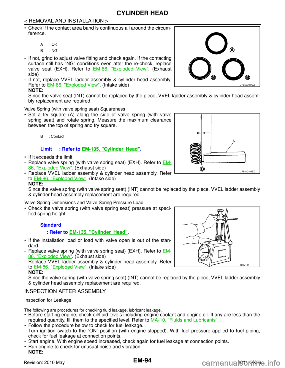
Check if the contact area band is continuous all around the circum-ference.
- If not, grind to adjust valve fitting and check again. If the contacting surface still has “NG” conditions even after the re-check, replace
valve seat (EXH). Refer to EM-86, "
Exploded View". (Exhaust
side)
- If not, replace VVEL ladder assembly & cylinder head assembly. Refer to EM-86, "
Exploded View". (Intake side)
NOTE:
Since the valve seat (INT) cannot be replaced by t he piece, VVEL ladder assembly & cylinder head assem-
bly replacement are required.
Valve Spring (with valve spring seat) Squareness
Set a try square (A) along the side of valve spring (with valve
spring seat) and rotate spring. Measure the maximum clearance
between the top of spring and try square.
If it exceeds the limit.
- Replace valve spring (with valve spring seat) (EXH). Refer to EM-
86, "Exploded View". (Exhaust side)
- Replace VVEL ladder assembly & cylinder head assembly. Refer
to EM-86, "
Exploded View". (Intake side)
NOTE:
Since the valve spring (with valve spring seat) (INT) c annot be replaced by the piece, VVEL ladder assembly
& cylinder head assembly replacement are required.
Valve Spring Dimensions and Valve Spring Pressure Load
Check the valve spring (with valve spring seat) pressure at speci- fied spring height.
If the installation load or load with valve open is out of the stan- dard.
- Replace valve spring (with valve spring seat) (EXH). Refer to EM-
86, "Exploded View". (Exhaust side)
- Replace VVEL ladder assembly & cylinder head assembly. Refer to EM-86, "
Exploded View". (Intake side)
NOTE:
Since the valve spring (with valve spring seat) (INT) c annot be replaced by the piece, VVEL ladder assembly
& cylinder head assembly replacement are required.
INSPECTION AFTER ASSEMBLY
Inspection for Leakage
The following are procedures for checking fluid leakage, lubricant leakage.
Before starting engine, check oil/fluid levels includi ng engine coolant and engine oil. If any are less than the
required quantity, fill them to the specified level. Refer to MA-10, "
Fluids and Lubricants".
Follow the procedure below to check for fuel leakage.
- Turn ignition switch to the “ON” position (with engi ne stopped). With fuel pressure applied to fuel piping,
check for fuel leakage at connection points.
- Start engine. With engine speed increased, che ck again for fuel leakage at connection points.
Run engine to check for unusual noise and vibration. NOTE:
A: OK
B: NG
JPBIA0187ZZ
B : Contact
Limit : Refer to EM-135, "CylinderHead".
JPBIA0189ZZ
Standard
: Refer to EM-135, "
CylinderHead".
SEM113
Revision: 2010 May2011 QX56
Page 2657 of 5598
CYLINDER HEADEM-95
< REMOVAL AND INSTALLATION >
C
DE
F
G H
I
J
K L
M A
EM
NP
O
If hydraulic pressure inside chain tensioner drops after removal/installation, slack in guide may generate a
pounding noise during and just after the engine start. However, this does not indicate a malfunction. The
noise will stop after hydraulic pressure rises.
Warm up engine thoroughly to check that there is no leak age of fuel, or any oil/fluids including engine oil and
engine coolant.
Bleed air from lines and hoses of applicable lines, such as in cooling system.
After cooling down engine, again check oil/fluid levels including engine oil and engine coolant. Refill them to
the specified level, if necessary.
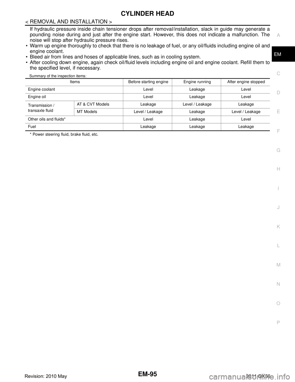
Summary of the inspection items:
* Power steering fluid, brake fluid, etc. Items Before starting engine Engine running After engine stopped
Engine coolant Level Leakage Level
Engine oil Level Leakage Level
Transmission /
transaxle fluid AT & CVT Models Leakage Level / Leakage Leakage
MT Models Level / Leakage Leakage Level / Leakage
Other oils and fluids* Level Leakage Level
Fuel Leakage Leakage Leakage
Revision: 2010 May2011 QX56
Page 2664 of 5598
EM-102
< UNIT REMOVAL AND INSTALLATION >
ENGINE ASSEMBLY
INSTALLATION
Install in the reverse order of removal.
CAUTION:
When replacing an engine or transmission you must make sure the dowels are installed correctly
during re-assembly.Improper alignment caused by mi ssing dowels may cause vibration, oil leaks or
breakage of drivetrain components.
InspectionINFOID:0000000006289578
INSPECTION AFTER INSTALLATION
Inspection for Leakage
The following are procedures for checking fluid leakage, lubricant leakage. Before starting engine, check oil/fluid levels includi ng engine coolant and engine oil. If any are less than the
required quantity, fill them to the specified level. Refer to MA-10, "
Fluids and Lubricants".
Follow the procedure below to check for fuel leakage.
- Turn ignition switch to the “ON” position (with engi ne stopped). With fuel pressure applied to fuel piping,
check for fuel leakage at connection points.
- Start engine. With engine speed increased, che ck again for fuel leakage at connection points.
Run engine to check for unusual noise and vibration. NOTE:
If hydraulic pressure inside chain tensioner drops af ter removal/installation, slack in guide may generate a
pounding noise during and just after the engine start. However, this does not indicate a malfunction. The
noise will stop after hydraulic pressure rises.
Warm up engine thoroughly to check that there is no leak age of fuel, or any oil/fluids including engine oil and
engine coolant.
Bleed air from lines and hoses of applic able lines, such as in cooling system.
After cooling down engine, again check oil/fluid levels including engine oil and engine coolant. Refill them to
the specified level, if necessary.
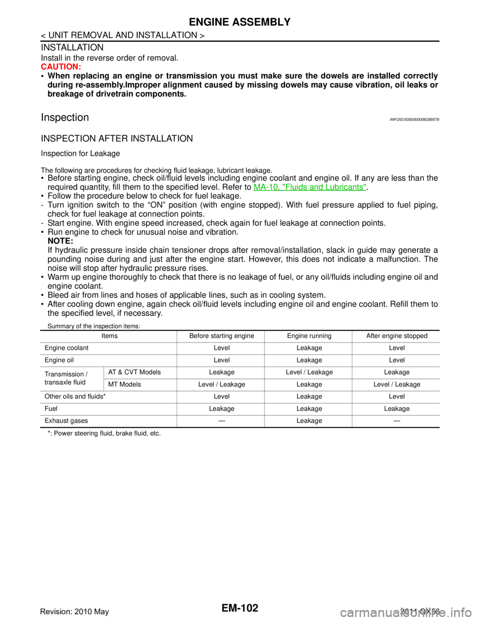
Summary of the inspection items:
*: Power steering fluid, brake fluid, etc. Items Before starting engine Engine running After engine stopped
Engine coolant Level Leakage Level
Engine oil Level Leakage Level
Transmission /
transaxle fluid AT & CVT Models Leakage Level / Leakage Leakage
MT Models Level / Leakage Leakage Level / Leakage
Other oils and fluids* Level Leakage Level
Fuel Leakage Leakage Leakage
Exhaust gases — Leakage —
Revision: 2010 May2011 QX56
Page 2726 of 5598
![INFINITI QX56 2011 Factory Service Manual
EXL-16
< SYSTEM DESCRIPTION >[XENON TYPE]
SYSTEM
- Swivels the headlamp to the vehicle-center side until it hits the stopper.
- Returns the swivel angle from the stopper. Completes t
he initializatio INFINITI QX56 2011 Factory Service Manual
EXL-16
< SYSTEM DESCRIPTION >[XENON TYPE]
SYSTEM
- Swivels the headlamp to the vehicle-center side until it hits the stopper.
- Returns the swivel angle from the stopper. Completes t
he initializatio](/img/42/57033/w960_57033-2725.png)
EXL-16
< SYSTEM DESCRIPTION >[XENON TYPE]
SYSTEM
- Swivels the headlamp to the vehicle-center side until it hits the stopper.
- Returns the swivel angle from the stopper. Completes t
he initialization with regarding the returned position
as the swivel angle 0 ° (straight-forward position).
Swivel Operation
AFS control unit transmits the drive signal to the sw ivel actuator when activation conditions are satisfied.
And swivels the headlamp.
- The swivel starts after steering approximately 20 ° or more from straight-forward position.
NOTE:
The steering angle differs between right turn and left turn.
- The swivel angle becomes the maximum angle toward t he driving direction if the steering angle is approxi-
mately 90 ° or more depending on the vehicle speed. The swivel angle is maintained by shutting off the drive
signal.
- The swivel starts, and returns to the swivel angle 0 ° (straight-forward position) when the steering is returned
to the straight-forward position.
AFS control unit returns the swivel angle to the strai ght-forward position, and stops the swivel regardless of
the steering angle if the operation condition is not satisfied while the swivel angle is 0°.
AFS OFF Indicator Lamp
AFS control unit transmits AFS OFF indicator lamp signal to the combination meter via CAN communication.
Combination meter turns AFS OFF indicator lamp ON /OFF/blinking according to AFS OFF indicator lamp
signal.
- AFS OFF indicator lamp is turned ON for 1 second for the AFS OFF indicator lamp bulb check when the igni-
tion switch is turned ON. AFS OFF indicator lamp is turned OFF within 1 second when the engine starts.
- AFS OFF indicator lamp turns ON when AFS is switched to “OFF” by operating AFS switch.
- AFS OFF indicator lamp blinks (1 second each) if AFS control unit detects a specific DTC.
NOTE:
Combination meter blinks AFS OFF indicator lamp (approximately 1 second each) if AFS OFF indicator
lamp signal is not received from AFS control unit.
HEADLAMP AUTO AIMING
Headlamp Auto Aiming Control Description
AFS control unit controls the headl amp light axis height appropriately according to the vehicle height.
AFS control unit detects the vehicle condition necessa ry for headlamp auto aiming control with the following
signals.
- Height sensor signals (front and rear)
- Vehicle speed signal (received from combination meter via CAN communication)
- Low beam status signal (received from IPDM E/R via CAN communication)
- Engine speed signal (received from ECM via CAN communication)
When the operation conditions are satisfied, AFS cont rol unit transmits the aiming motor drive signal for
adjusting the headlamp axis height.
Headlamp auto aiming operation condition- Headlamp ON
- While the engine running
- Vehicle speed (Control mode is switched according to the driving condition.)
Headlamp Auto Aiming Operation
AFS control unit calculates the vehicle pitch angle fr om the front and rear height sensor signal. AFS control
unit judges the angle for adjusting the axis gap from the preset position.
AFS control unit controls the headlamp axis by c hanging the aiming motor drive signal output according to
the front and rear vehicle height when detecting the follo wing vehicle condition. Output is maintained if other
condition than following is detected.
- Engine starts.
- Headlamp is turned ON.
- Vehicle posture becomes stable after changing the v ehicle posture change is detected with the headlamp
ON and the vehicle stopped.
- Vehicle speed is maintained with the headlamp ON and the vehicle driven.
CAUTION:
Adjusted axis position may differ from the preset position although the headlamp auto aiming acti-
vates properly if the suspension is replaced or worn.
Revision: 2010 May2011 QX56
Page 2775 of 5598
![INFINITI QX56 2011 Factory Service Manual
B2503, B2504 SWIVEL ACTUATOREXL-65
< DTC/CIRCUIT DIAGNOSIS > [XENON TYPE]
C
D
E
F
G H
I
J
K
M A
B
EXL
N
O P
Is the inspection result normal?
YES >> GO TO 5.
NO >> Repair or replace harnesses.
5.CHECK INFINITI QX56 2011 Factory Service Manual
B2503, B2504 SWIVEL ACTUATOREXL-65
< DTC/CIRCUIT DIAGNOSIS > [XENON TYPE]
C
D
E
F
G H
I
J
K
M A
B
EXL
N
O P
Is the inspection result normal?
YES >> GO TO 5.
NO >> Repair or replace harnesses.
5.CHECK](/img/42/57033/w960_57033-2774.png)
B2503, B2504 SWIVEL ACTUATOREXL-65
< DTC/CIRCUIT DIAGNOSIS > [XENON TYPE]
C
D
E
F
G H
I
J
K
M A
B
EXL
N
O P
Is the inspection result normal?
YES >> GO TO 5.
NO >> Repair or replace harnesses.
5.CHECK SWIVEL MOTOR CIRCUIT VOLTAGE OUTPUT
1. Connect AFS control unit connector.
2. Start the engine.
3. Turn the headlamp ON.
4. Select “LOW BEAM TEST RIGHT” or “LOW BEAM TEST LEFT” of ADAPTIVE LIGHT active test item.
5. With operating the test item, check voltage between AFS control unit harness connector and ground.
Is the inspection result normal?
YES >> Replace front combination lamp.
NO >> Replace AFS control unit. Refer to EXL-135, "
Removal and Installation"
6.CHECK SWIVEL POSITION SENSOR POWER SUPPLY CIRCUIT INPUT VOLTAGE
1. Turn ignition switch OFF.
2. Disconnect headlamp swivel actuator connector.
3. Turn ignition switch ON.
4. Check voltage between headlamp swivel actuator harness connector and ground.
AFS control unit
GroundContinuity
Connector Terminal
RH M135 11
Not existed
13
32
34
LH 15
17
36
38
(+)
(− ) Condition Vo l ta g e
(Approx.)
AFS control unit
Connector Terminal
RH
M135 11
Ground Swivel motor Active
8 - 12 V
32
LH 15
36
RH 13
Stop 9.5 - 11.5 V
34
LH 17
38
SKIB2408J
(+)
(− ) Vol tag e
(Approx.)
Headlamp swivel actuator
Connector Terminal
RH E123 2Ground5 V
LH E122
Revision: 2010 May2011 QX56