engine coolant INFINITI QX56 2011 Factory Service Manual
[x] Cancel search | Manufacturer: INFINITI, Model Year: 2011, Model line: QX56, Model: INFINITI QX56 2011Pages: 5598, PDF Size: 94.53 MB
Page 3806 of 5598

MWI
B2268 WATER TEMPMWI-63
< DTC/CIRCUIT DIAGNOSIS >
C
DE
F
G H
I
J
K L
M B A
O P
B2268 WATER TEMP
DescriptionINFOID:0000000006221740
The engine coolant temperature signal is transmitted from ECM to the combination meter via CAN communi-
cation.
DTC LogicINFOID:0000000006221741
DTC DETECTION LOGIC
Diagnosis ProcedureINFOID:0000000006221742
1.PERFORM SELF-DIAGNOSIS OF ECM
Perform “Self Diagnosis Result” of ECM, and repair or replace malfunctioning parts.
>> Refer to EC-98, "
DTC Index".
DTCDisplay contents of
CONSULT-III Diagnostic item is detected when... Probable malfunction location
B2268 WATER TEMP ECM continuously transmits abnormal engine
coolant temperature signals for 60 seconds or
more Engine coolant temperature sensor
ECM
Revision: 2010 May2011 QX56
Page 3856 of 5598
![INFINITI QX56 2011 Factory Service Manual
PCS
IPDM E/RPCS-15
< ECU DIAGNOSIS INFORMATION > [IPDM E/R]
C
D
E
F
G H
I
J
K L
B A
O P
N
ECU DIAGNOSIS INFORMATION
IPDM E/R
Reference ValueINFOID:0000000006220172
VALUES ON THE DIAGNOSIS TOOL
Monito INFINITI QX56 2011 Factory Service Manual
PCS
IPDM E/RPCS-15
< ECU DIAGNOSIS INFORMATION > [IPDM E/R]
C
D
E
F
G H
I
J
K L
B A
O P
N
ECU DIAGNOSIS INFORMATION
IPDM E/R
Reference ValueINFOID:0000000006220172
VALUES ON THE DIAGNOSIS TOOL
Monito](/img/42/57033/w960_57033-3855.png)
PCS
IPDM E/RPCS-15
< ECU DIAGNOSIS INFORMATION > [IPDM E/R]
C
D
E
F
G H
I
J
K L
B A
O P
N
ECU DIAGNOSIS INFORMATION
IPDM E/R
Reference ValueINFOID:0000000006220172
VALUES ON THE DIAGNOSIS TOOL
Monitor Item Condition Value/Status
RAD FAN REQ Engine idle speed Changes depending on engine
coolant temperature, air condition-
er operation status, vehicle speed,
etc.0 – 100 %
AC COMP REQ Engine running A/C switch OFF Off
A/C switch ON
(Compressor is operating)
On
TAIL&CLR REQ Lighting switch OFF Off
Lighting switch 1ST, 2ND or AUTO (Light is illuminated) On
HL LO REQ Lighting switch OFF Off
Lighting switch 2ND or AUTO (Light is illuminated) On
HL HI REQ Lighting switch 2ND or
AUTO (Light is illuminated) Lighting switch other than HI and
PA S S
Off
Lighting switch HI or PASS On
FR FOG REQ Lighting switch 2ND or
AUTO (Light is illuminated) Front fog lamp switch OFF Off
Front fog lamp switch ON On
FR WIP REQ Ignition switch ON Front wiper switch OFF Stop
Front wiper switch INT 1LOW
Front wiper switch LO Low
Front wiper switch HI Hi
WIP AUTO STOP Ignition switch ON Front wiper stop position STOP P
Any position other than front wiper
stop position
ACT P
WIP PROT Ignition switch ON Front wiper operates normally. Off
Front wiper stops at fail-safe opera-
tion.
BLOCK
IGN RLY1 -REQ Ignition switch OFF or ACC Off
Ignition switch ON On
IGN RLY Ignition switch OFF or ACC Off
Ignition switch ON On
PUSH SW Release the push-button ignition switch Off
Press the push-button ignition switch On
INTER/NP SW Ignition switch ON Selector lever in any position other
than P or N
Off
Selector lever in P or N position On
ST RLY CONT Ignition switch ON Off
At engine cranking On
IHBT RLY -REQ Ignition switch ON Off
At engine cranking On
Revision: 2010 May2011 QX56
Page 4257 of 5598

RSU-2
< PRECAUTION >
PRECAUTIONS
PRECAUTION
PRECAUTIONS
Precautions for SuspensionINFOID:0000000006225656
• When installing rubber bushings, the final tightening must be carried out under unladen conditions with tires
on ground. Spilled oil might shorten the life of rubber bushings. Be sure to wipe off any spilled oil.
- Unladen conditions mean that fuel, engine coolant and l ubricant are full. Spare tire, jack, hand tools and
mats are in designated positions.
After servicing suspension parts, be sure to check wheel alignment.
Self-lock nuts are not reusable. Always use new ones when installing. Since new self-lock nuts are pre-oiled,
tighten as they are.
Revision: 2010 May2011 QX56
Page 4261 of 5598

RSU-6
< PERIODIC MAINTENANCE >
WHEEL ALIGNMENT
WHEEL ALIGNMENT
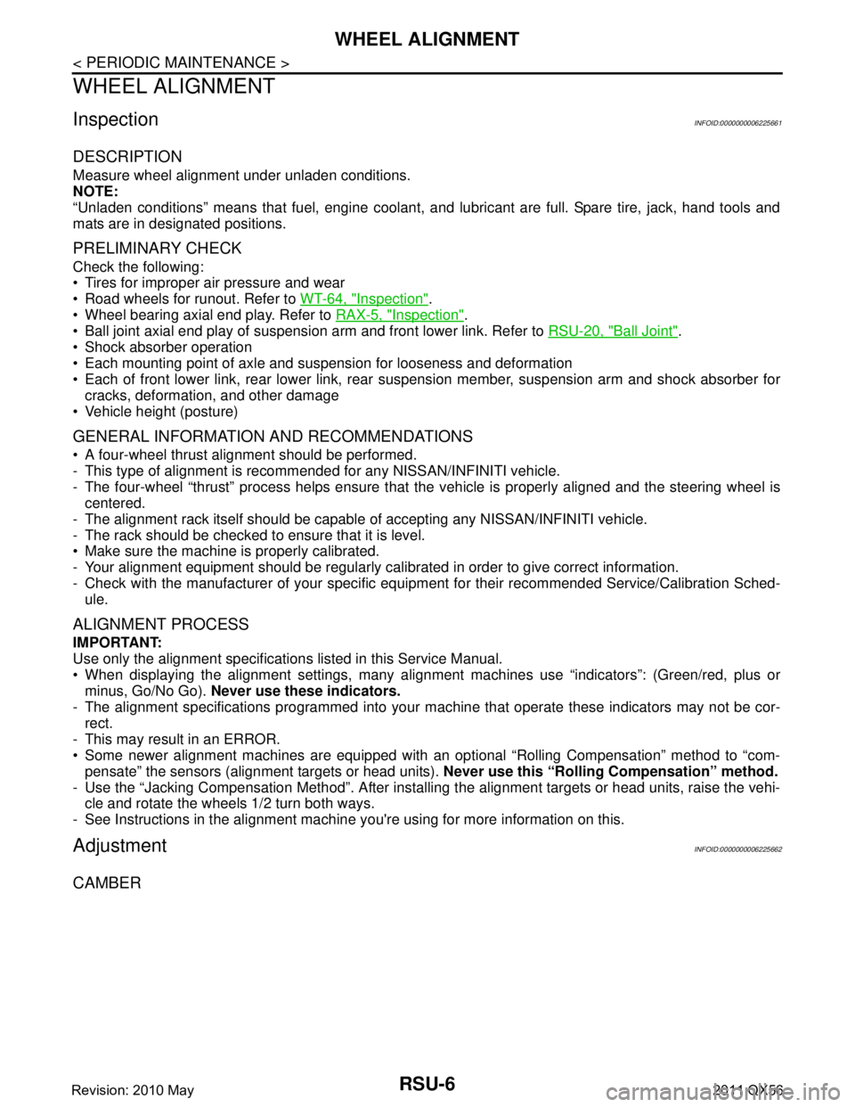
InspectionINFOID:0000000006225661
DESCRIPTION
Measure wheel alignment under unladen conditions.
NOTE:
“Unladen conditions” means that fuel, engine coolant, and lubricant are full. Spare tire, jack, hand tools and
mats are in designated positions.
PRELIMINARY CHECK
Check the following:
Tires for improper air pressure and wear
Road wheels for runout. Refer to WT-64, "
Inspection".
Wheel bearing axial end play. Refer to RAX-5, "
Inspection".
Ball joint axial end play of suspension arm and front lower link. Refer to RSU-20, "
Ball Joint".
Shock absorber operation
Each mounting point of axle and suspension for looseness and deformation
Each of front lower link, rear lower link, rear suspension member, suspension arm and shock absorber for
cracks, deformation, and other damage
Vehicle height (posture)
GENERAL INFORMATION AND RECOMMENDATIONS
A four-wheel thrust alignment should be performed.
- This type of alignment is recomm ended for any NISSAN/INFINITI vehicle.
- The four-wheel “thrust” process helps ensure that t he vehicle is properly aligned and the steering wheel is
centered.
- The alignment rack itself should be capable of accepting any NISSAN/INFINITI vehicle.
- The rack should be checked to ensure that it is level.
Make sure the machine is properly calibrated.
- Your alignment equipment should be regularly calib rated in order to give correct information.
- Check with the manufacturer of your specific equi pment for their recommended Service/Calibration Sched-
ule.
ALIGNMENT PROCESS
IMPORTANT:
Use only the alignment specifications listed in this Service Manual.
When displaying the alignment settings, many alignment machines use “indicators”: (Green/red, plus or
minus, Go/No Go). Never use these indicators.
- The alignment specifications programmed into your machine that operate these indicators may not be cor-
rect.
- This may result in an ERROR.
Some newer alignment machines are equipped with an optional “Rolling Compensation” method to “com- pensate” the sensors (alignment targets or head units). Never use this “Rolling Compensation” method.
- Use the “Jacking Compensation Method”. After installi ng the alignment targets or head units, raise the vehi-
cle and rotate the wheels 1/2 turn both ways.
- See Instructions in the alignment machine you're using for more information on this.
AdjustmentINFOID:0000000006225662
CAMBER
Revision: 2010 May2011 QX56
Page 4275 of 5598

RSU-20
< SERVICE DATA AND SPECIFICATIONS (SDS)
SERVICE DATA AND SPECIFICATIONS (SDS)
SERVICE DATA AND SPECIFICATIONS (SDS)
SERVICE DATA AND SPECIFICATIONS (SDS)
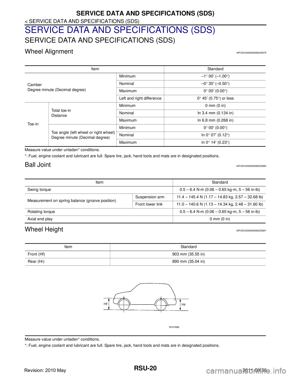
Wheel AlignmentINFOID:0000000006225679
Measure value under unladen* conditions.
*: Fuel, engine coolant and lubricant are full. Spare tire, jack, hand tools and mats are in designated positions.
Ball JointINFOID:0000000006225680
Wheel HeightINFOID:0000000006225681
Measure value under unladen* conditions.
*: Fuel, engine coolant and lubricant are full. Spare tire, jack, hand tools and mats are in designated positions.Item Standard
Camber
Degree minute (Decimal degree) Minimum –1
° 00 ′ (–1.00 °)
Nominal –0 ° 30 ′ (–0.50 °)
Maximum 0 ° 00 ′ (0.00 °)
Left and right difference 0 ° 45 ′ (0.75 °) or less
To e - i n Total toe-in
Distance
Minimum 0 mm (0 in)
Nominal In 3.4 mm (0.134 in)
Maximum In 6.8 mm (0.268 in)
Toe angle (left wheel or right wheel)
Degree minute (Decimal degree) Minimum 0
° 00 ′ (0.00 °)
Nominal In 0 ° 07 ′ (0.12 °)
Maximum In 0 ° 14 ′ (0.23 °)
Item Standard
Swing torque 0.5 – 6.4 N·m (0.06 – 0.65 kg-m, 5 – 56 in-lb)
Measurement on spring balance (groove position) Suspension arm 11.4 – 145.4 N (1.17 – 14.83 kg, 2.57 – 32.68 lb)
Front lower link 11.0 – 140.6 N (1.13 – 14.34 kg, 2.48 – 31.60 lb)
Rotating torque 0.5 – 6.4 N·m (0.06 – 0.65 kg-m, 5 – 56 in-lb)
Axial end play 0 mm (0 in)
Item Standard
Front (Hf) 903 mm (35.55 in)
Rear (Hr) 890 mm (35.04 in)
SFA746B
Revision: 2010 May2011 QX56
Page 5080 of 5598

STR-12
< BASIC INSPECTION >
DIAGNOSIS AND REPAIR WORKFLOW
NOTE:
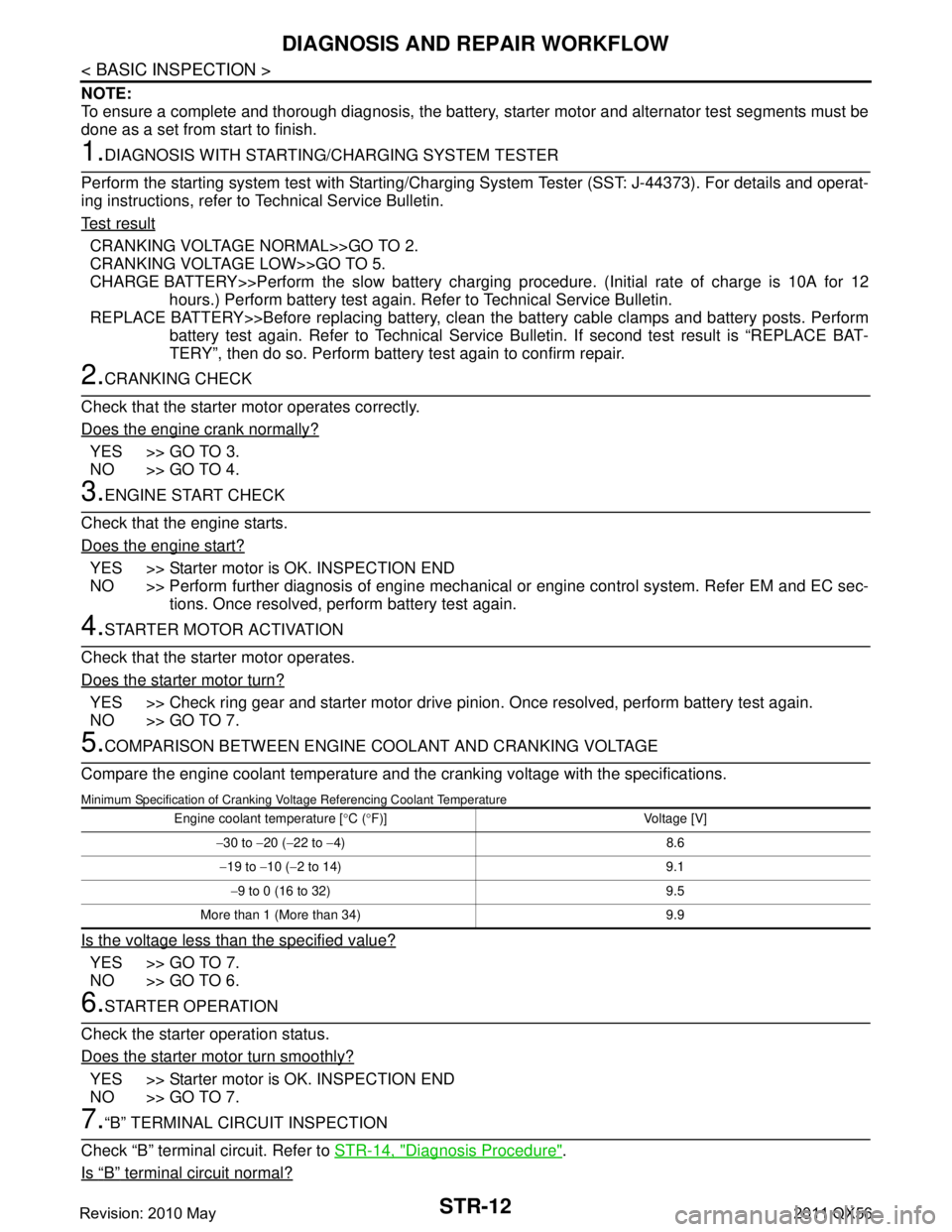
To ensure a complete and thorough diagnosis, the battery, starter motor and alternator test segments must be
done as a set from start to finish.
1.DIAGNOSIS WITH STARTING /CHARGING SYSTEM TESTER
Perform the starting system test with Starting/Char ging System Tester (SST: J-44373). For details and operat-
ing instructions, refer to Technical Service Bulletin.
Te s t r e s u l t
CRANKING VOLTAGE NORMAL>>GO TO 2.
CRANKING VOLTAGE LOW>>GO TO 5.
CHARGE BATTERY>>Perform the slow battery charging procedure. (Initial rate of charge is 10A for 12
hours.) Perform battery test again. Re fer to Technical Service Bulletin.
REPLACE BATTERY>>Before replacing battery, clean t he battery cable clamps and battery posts. Perform
battery test again. Refer to Technical Service Bu lletin. If second test result is “REPLACE BAT-
TERY”, then do so. Perform battery test again to confirm repair.
2.CRANKING CHECK
Check that the starter motor operates correctly.
Does the engine crank normally?
YES >> GO TO 3.
NO >> GO TO 4.
3.ENGINE START CHECK
Check that the engine starts.
Does the engine start?
YES >> Starter motor is OK. INSPECTION END
NO >> Perform further diagnosis of engine mechanical or engine control system. Refer EM and EC sec-
tions. Once resolved, perform battery test again.
4.STARTER MOTOR ACTIVATION
Check that the starter motor operates.
Does the starter motor turn?
YES >> Check ring gear and starter motor drive pinion. Once resolved, perform battery test again.
NO >> GO TO 7.
5.COMPARISON BETWEEN ENGINE COOLANT AND CRANKING VOLTAGE
Compare the engine coolant temperature and the cranking voltage with the specifications.
Minimum Specification of Cranking Voltage Referencing Coolant Temperature
Is the voltage less than the specified value?
YES >> GO TO 7.
NO >> GO TO 6.
6.STARTER OPERATION
Check the starter operation status.
Does the starter motor turn smoothly?
YES >> Starter motor is OK. INSPECTION END
NO >> GO TO 7.
7.“B” TERMINAL CIRCUIT INSPECTION
Check “B” terminal circuit. Refer to STR-14, "
Diagnosis Procedure".
Is
“B” terminal circuit normal?
Engine coolant temperature [ °C ( °F)] Voltage [V]
− 30 to −20 ( −22 to −4) 8.6
− 19 to −10 ( −2 to 14) 9.1
− 9 to 0 (16 to 32) 9.5
More than 1 (More than 34) 9.9
Revision: 2010 May2011 QX56
Page 5130 of 5598
![INFINITI QX56 2011 Factory Service Manual
TM-42
< SYSTEM DESCRIPTION >[7AT: RE7R01B]
STRUCTURE AND OPERATION
A/T FLUID COOLER SCHEMATIC
COMPONENT DESCRIPTION
A/T fluid warmer
The A/T fluid warmer (1) is installed on the front part of cylin INFINITI QX56 2011 Factory Service Manual
TM-42
< SYSTEM DESCRIPTION >[7AT: RE7R01B]
STRUCTURE AND OPERATION
A/T FLUID COOLER SCHEMATIC
COMPONENT DESCRIPTION
A/T fluid warmer
The A/T fluid warmer (1) is installed on the front part of cylin](/img/42/57033/w960_57033-5129.png)
TM-42
< SYSTEM DESCRIPTION >[7AT: RE7R01B]
STRUCTURE AND OPERATION
A/T FLUID COOLER SCHEMATIC
COMPONENT DESCRIPTION
A/T fluid warmer
The A/T fluid warmer (1) is installed on the front part of cylinder
block of engine.
When engine is started while engine and A/T are cold, engine cool-
ant temperature rises more quickly than A/T fluid temperature. A/T
fluid warmer is provided with two circuits for ATF and engine cool-
ant respectively so that warmed engine coolant warms ATF
quickly. This helps shorten A/T warming up time, improving fuel
economy.
A cooling effect is obtained when A/T fluid temperature is high.
A/T fluid cooler (with bypass valve)
A/T fluid cooler (1) is installed in the front of radiator (2) and con- denser (3).
A/T fluid cooler is provided with a bypass valve that controls ATF
flow. Bypass valve operates by thermo wax and a return spring.
Bypass valve fully opens when A/T fluid temperature is approxi-
mately 90 °C (194 °F) and fully closes when A/T fluid temperature is
approximately 100 °C (212 °F).
When A/T fluid temperature is low, the bypass valve is open. Most of ATF therefore returns to the transmission without flowing into the
cooler core that has larger flow resistance.
JSDIA1803GB
JSDIA1811ZZ
JSDIA1814ZZ
JSDIA1815GB
Revision: 2010 May2011 QX56
Page 5411 of 5598

WCS
SYSTEMWCS-7
< SYSTEM DESCRIPTION >
C
DE
F
G H
I
J
K L
M B A
O P
WARNING CHIME SYSTEM : Fail-SafeINFOID:0000000006369726
FA I L - S A F E
The combination meter activates the fail-safe contro l if CAN communication with each unit is malfunctioning.
Seat belt warning chimeThe warning chime sounds when the driver
seat belt is unfastened with the ignition switch
in ON position. BCMWCS-11,
"SEAT BELT
WARNING
CHIME : Sys-
tem Descrip-
tion"
Parking brake release warning chime
The warning chime sounds when the ignition
switch is in ON position with the parking brake
in operation and the vehicle speed 7 km/h (4.3
MPH) or more. Combination meterWCS-12,
"PA R K I N G
BRAKE RE-
LEASE WARN-
ING CHIME :
System De-
scription"
Warning functions Out line Warning judgment unit Refer to
Function Specifications
Speedometer
Reset to zero by suspending communication.
Tachometer
Engine coolant temperature gauge
Engine oil pressure gauge
Illumination control When suspending communication, changes to nighttime mode.
Information display Odo/trip meter An indicated value is maintained at communications blackout.
Shift position indicator The display turns OFF by suspending communication.
Door open warning The display turns OFF by suspending communication.
Buzzer The buzzer turns OFF by suspending communication.
Revision: 2010 May2011 QX56
Page 5418 of 5598

WCS-14
< SYSTEM DESCRIPTION >
DIAGNOSIS SYSTEM (COMBINATION METER)
DIAGNOSIS SYSTEM (COMBINATION METER)
CONSULT-III FunctionINFOID:0000000006222742
CONSULT-III APPLICATION ITEMS
CONSULT-III can perform the following diagnosis modes via CAN communication and the combination meter.
SELF DIAG RESULT
Refer to MWI-43, "DTC Index".
DATA MONITOR
Display Item List
X: Applicable
System Diagnosis mode Description
METER/M&A Self Diagnostic Result The combination meter checks the conditions and displays memorized errors.
Data Monitor Displays the combination meter input/output data in real time.
Special function Lighting history of the warning lamp and indicator lamp can be checked.
Display item [Unit]
MAIN
SIGNALS Description
SPEED METER
[km/h] XValue of vehicle speed
signal received from ABS actuator and el ectric unit (control
unit) via CAN communication.
NOTE:
655.35 is displayed when the malfunction signal is received.
SPEED OUTPUT
[km/h] XVehicle speed signal value transmitted to other units via CAN communication.
NOTE:
655.35 is displayed when the malfunction signal is received.
ODO OUTPUT
[km/h or mph] Odometer signal value transmitted to other units via CAN communication.
TACHO METER
[rpm] XValue of the engine speed signal received from ECM via CAN communication.
NOTE:
8191.875 is displayed when the malfunction signal is received.
FUEL METER
[L] X Fuel level indicated on combination meter.
W TEMP METER
[ ° C] XValue of engine coolant temperature signal is received from ECM via CAN com-
munication.
NOTE:
215 is displayed when the malfunction signal is input.
ABS W/L
[On/Off] Status of ABS warning lamp
detected from ABS warning lamp signal is received
from ABS actuator and electric unit (control unit) via CAN communication.
VDC/TCS IND
[On/Off] Status of VDC OFF indicator lamp detected from VDC OFF indicator lamp signal
is received from ABS actuator and electric
unit (control unit) via CAN communica-
tion.
SLIP IND
[On/Off] Status of VDC warning lamp detected from VDC warning lamp signal received
from ABS actuator and electric unit (control unit) via CAN communication.
BRAKE W/L
[On/Off] Status of brake warning lamp detected from brake warning lamp signal is received
from ABS actuator and electric unit (control unit) via CAN communication.
NOTE:
Displays “Off” if the brake warning lamp is illuminated when the valve check starts,
the parking brake switch is turned ON or the brake fluid level switch is turned ON.
DOOR W/L
[On/Off] Status of door open warning detected from door switch signal received from BCM
via CAN communication.
HI-BEAM IND
[On/Off] Status of high beam indicator lamp detected from high beam request signal is re-
ceived from BCM via CAN communication.
TURN IND
[On/Off] Status of turn indicator lamp detected from turn indicator signal is received from
BCM via CAN communication.
Revision: 2010 May2011 QX56
Page 5426 of 5598

WCS-22
< ECU DIAGNOSIS INFORMATION >
COMBINATION METER
ECU DIAGNOSIS INFORMATION
COMBINATION METER
Reference ValueINFOID:0000000006222688
VALUES ON THE DIAGNOSIS TOOL
Monitor Item Condition Value/Status
SPEED METER
[km/h] Ignition switch
ON
While driving Input value of vehicle speed signal
(CAN communication signal)
NOTE:
655.35 is displayed when the malfunc-
tion signal is received
SPEED OUTPUT
[km/h] Ignition switch
ON
While driving Output value of vehicle speed signal
(CAN communication signal)
NOTE:
655.35 is displayed when the malfunc-
tion signal is received
ODO OUTPUT
[km/h or mph] Ignition switch
ON
—Output value of odometer signal (CAN
communication signal)
TACHO METER
[rpm] Ignition switch
ON
Engine running Input value of engine speed signal
(CAN communication signal)
NOTE:
8191.875 is displayed when the mal-
function signal is received
FUEL METER
[L] Ignition switch
ON
— Input value of fuel level sensor signal
W TEMP METER
[ ° C] Ignition switch
ON
—Input value of engine coolant tempera-
ture signal (CAN communication sig-
nal)
NOTE:
215 is displayed when the malfunction
signal is input
ABS W/L Ignition switch
ONABS warning lamp ON On
ABS warning lamp OFF Off
VDC/TCS IND Ignition switch
ONVDC OFF indicator lamp ON On
VDC OFF indicator lamp OFF Off
SLIP IND Ignition switch
ONVDC warning lamp ON On
VDC warning lamp OFF Off
BRAKE W/L Ignition switch
ONBrake warning lamp ON On
Brake warning lamp OFF Off
DOOR W/L Ignition switch
ONDoor open warning ON On
Other than the above Off
HI-BEAM IND Ignition switch
ONHigh-beam indicator lamp ON On
High-beam indicator lamp OFF Off
TURN IND Ignition switch
ONTurn signal indicator lamp ON On
Turn signal indicator lamp OFF Off
FR FOG IND Ignition switch
ONNOTE:
This item is displayed, but cannot be moni-
tored.
Off
RR FOG IND Ignition switch
ONNOTE:
This item is displayed, but cannot be moni-
tored.
Off
Revision: 2010 May2011 QX56