power steering fluid INFINITI QX56 2011 Factory User Guide
[x] Cancel search | Manufacturer: INFINITI, Model Year: 2011, Model line: QX56, Model: INFINITI QX56 2011Pages: 5598, PDF Size: 94.53 MB
Page 2657 of 5598

CYLINDER HEADEM-95
< REMOVAL AND INSTALLATION >
C
DE
F
G H
I
J
K L
M A
EM
NP
O
If hydraulic pressure inside chain tensioner drops after removal/installation, slack in guide may generate a
pounding noise during and just after the engine start. However, this does not indicate a malfunction. The
noise will stop after hydraulic pressure rises.
Warm up engine thoroughly to check that there is no leak age of fuel, or any oil/fluids including engine oil and
engine coolant.
Bleed air from lines and hoses of applicable lines, such as in cooling system.
After cooling down engine, again check oil/fluid levels including engine oil and engine coolant. Refill them to
the specified level, if necessary.
Summary of the inspection items:
* Power steering fluid, brake fluid, etc. Items Before starting engine Engine running After engine stopped
Engine coolant Level Leakage Level
Engine oil Level Leakage Level
Transmission /
transaxle fluid AT & CVT Models Leakage Level / Leakage Leakage
MT Models Level / Leakage Leakage Level / Leakage
Other oils and fluids* Level Leakage Level
Fuel Leakage Leakage Leakage
Revision: 2010 May2011 QX56
Page 2662 of 5598

EM-100
< UNIT REMOVAL AND INSTALLATION >
ENGINE ASSEMBLY
3. Install engine slinger on both front right and front left sides of theengine.
4. Hoist the slinger to obtain room for engine assembly. CAUTION:
Use an engine lifter to prevent the engine slinger from fall-
ing and damaging the rocker cover.
REMOVAL
Outline
At first, remove the transmission and transfer assemb ly, steering gear and front final drive facing downward.
Then remove the engine.
Preparation
1. Remove engine cover. Refer to EM-25, "Exploded View".
2. Release fuel pressure. Refer to EC-153, "
Work Procedure".
3. Remove battery and tray. Refer to PG-164, "
Exploded View".
4. Remove the following components and related parts: Hood assembly. Refer to DLK-215, "
Exploded View".
Front under cover. Refer to EXT-25, "
Exploded View".
Front road wheel and tires. Refer to WT-64, "
Exploded View".
5. Drain engine oil. Refer to LU-8, "
Draining".
6. Drain engine coolant. Refer to CO-8, "
Draining".
CAUTION:
Perform this step when engine is cold.
Never spill engine coolant on drive belts.
7. Drain power steering fluid. Refer to ST-54, "
Exploded View".
Engine Room Front
1. Remove drive belt. Refer to EM-20, "Exploded View".
2. Remove fan shroud. Refer to CO-13, "
Exploded View".
3. Remove cooling fan and fan coupling. Refer to CO-16, "
Exploded View".
4. Remove radiator hoses (upper and lower).
5. Remove radiator.
Vehicle Underbody
1. Remove exhaust front tube. Refer to EX-5, "Exploded View".
2. Remove protector A and B. Refer to SCS-32, "
FRONT TUBE ASSEMBLY : Exploded View".
3. Remove front suspension rear cross member. Refer to TM-205, "
2WD : Exploded View" (2WD models) or
TM-208, "
4WD : Exploded View" (4WD models).
4. Remove oil cooler. Refer to LU-11, "
Exploded View".
A : Engine front slinger (bank 2)
B : Engine front slinger (bank 1)
Slinger bolts:
: 45.0 N·m (4.6 kg-m, 33 ft-lb)
JPBIA3969ZZ
JPBIA2507ZZ
Revision: 2010 May2011 QX56
Page 2664 of 5598

EM-102
< UNIT REMOVAL AND INSTALLATION >
ENGINE ASSEMBLY
INSTALLATION
Install in the reverse order of removal.
CAUTION:
When replacing an engine or transmission you must make sure the dowels are installed correctly
during re-assembly.Improper alignment caused by mi ssing dowels may cause vibration, oil leaks or
breakage of drivetrain components.
InspectionINFOID:0000000006289578
INSPECTION AFTER INSTALLATION
Inspection for Leakage
The following are procedures for checking fluid leakage, lubricant leakage. Before starting engine, check oil/fluid levels includi ng engine coolant and engine oil. If any are less than the
required quantity, fill them to the specified level. Refer to MA-10, "
Fluids and Lubricants".
Follow the procedure below to check for fuel leakage.
- Turn ignition switch to the “ON” position (with engi ne stopped). With fuel pressure applied to fuel piping,
check for fuel leakage at connection points.
- Start engine. With engine speed increased, che ck again for fuel leakage at connection points.
Run engine to check for unusual noise and vibration. NOTE:
If hydraulic pressure inside chain tensioner drops af ter removal/installation, slack in guide may generate a
pounding noise during and just after the engine start. However, this does not indicate a malfunction. The
noise will stop after hydraulic pressure rises.
Warm up engine thoroughly to check that there is no leak age of fuel, or any oil/fluids including engine oil and
engine coolant.
Bleed air from lines and hoses of applic able lines, such as in cooling system.
After cooling down engine, again check oil/fluid levels including engine oil and engine coolant. Refill them to
the specified level, if necessary.
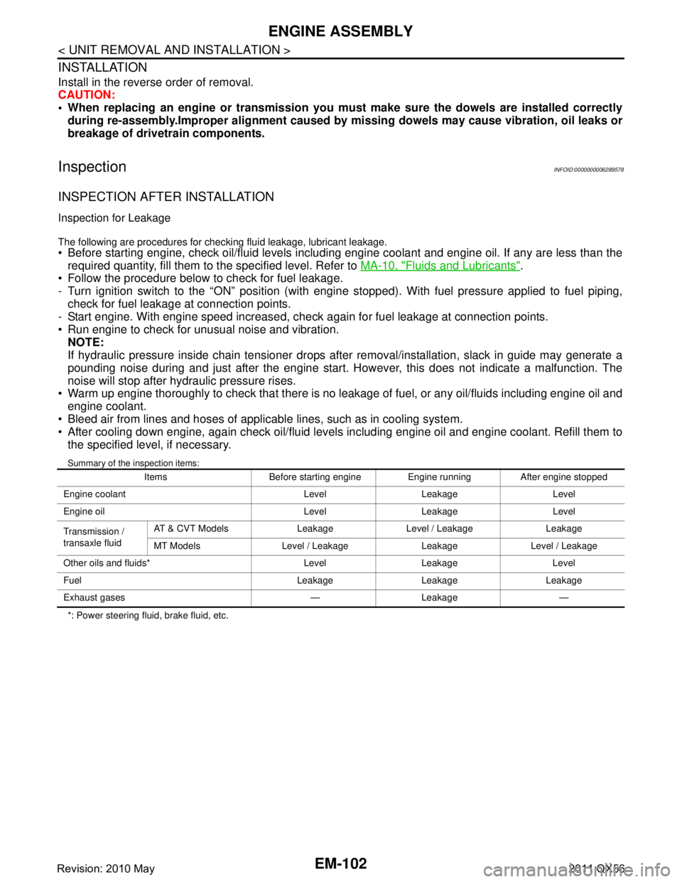
Summary of the inspection items:
*: Power steering fluid, brake fluid, etc. Items Before starting engine Engine running After engine stopped
Engine coolant Level Leakage Level
Engine oil Level Leakage Level
Transmission /
transaxle fluid AT & CVT Models Leakage Level / Leakage Leakage
MT Models Level / Leakage Leakage Level / Leakage
Other oils and fluids* Level Leakage Level
Fuel Leakage Leakage Leakage
Exhaust gases — Leakage —
Revision: 2010 May2011 QX56
Page 2952 of 5598

FSU-10
< REMOVAL AND INSTALLATION >
FRONT COIL SPRING AND SHOCK ABSORBER
CAUTION:
The shock absorber assembly cannot be disassembled.
Removal and InstallationINFOID:0000000006225643
REMOVAL
1. Reduce system pressure. (With HBMC) Refer to SCS-18, "Work Procedure".
CAUTION:
Inadvertent piping removal causes fluid to splatter.
2. Remove tires with power tool. Refer to WT-64, "
Removal and Installation".
3. Remove brake hose bracket from steering knuckle. Refer to BR-23, "
FRONT : Removal and Installation".
4. Remove caliper assembly mounting bolts. Hang caliper assembly in a place where it will not interfere with work. Refer to BR-37, "
BRAKE CALIPER ASSEMBLY : Removal and Installation".
CAUTION:
Never depress brake pedal while brake caliper is removed.
5. Remove disc rotor. Refer to FA X - 8 , "
Removal and Installation" (2WD), FAX-18, "Removal and Installation"
(4WD).
6. Remove wheel sensor and harness connector. Refer to BRC-134, "
FRONT WHEEL SENSOR : Removal
and Installation".
CAUTION:
Never pull on wheel sensor harness.
7. Remove steering outer socket fr om steering knuckle. Refer to ST-42, "
Removal and Installation".
8. Remove height sensor from upper link (right side). Refer to EXL-136, "
Removal and Installation".
9. Set suitable jack under lower link.
10. Remove stabilizer connecting rod from lower link. (Without HBMC) Refer to FSU-20, "
Removal and Instal-
lation".
11. Separate upper link from steering knuckle. Refer to FSU-17, "
Removal and Installation".
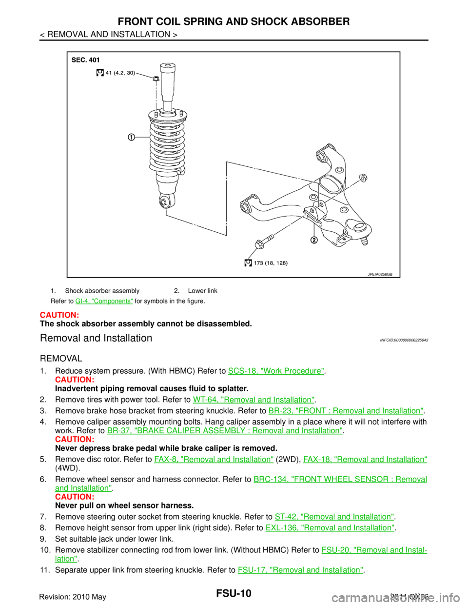
1. Shock absorber assembly 2. Lower link
Refer to GI-4, "
Components" for symbols in the figure.
JPEIA0256GB
Revision: 2010 May2011 QX56
Page 3672 of 5598

MA-2
FRONT DIFFERENTIAL GEAR OIL: R180A :
Draining ..................................................................
24
FRONT DIFFERENTIAL GEAR OIL: R180A : Re-
filling .......................................................................
25
REAR DIFFERENTIAL GEAR OIL: R230 ............. ...25
REAR DIFFERENTIAL GEAR OIL: R230 : Inspec-
tion ..........................................................................
25
REAR DIFFERENTIAL GEAR OIL: R230 : Drain-
ing ...........................................................................
25
REAR DIFFERENTIAL GEAR OIL: R230 : Refill-
ing ...........................................................................
26
WHEELS (BONDING WEIGHT TYPE) .....................26
WHEELS (BONDING WEIGHT TYPE) : Adjust-
ment ..................................................................... ...
26
BRAKE FLUID LEVEL AND LEAKS ........................27
BRAKE FLUID LEVEL AND LEAKS : Inspection ...28
BRAKE LINES AND CABLES ............................... ...28
BRAKE LINES AND CABLES : Inspection .............28
BRAKE FLUID ....................................................... ...28
BRAKE FLUID : Bleeding Brake System ................28
DISC BRAKE ......................................................... ...30
DISC BRAKE : Inspection ......................................30
DISC BRAKE : Front Disc Brake ............................31
DISC BRAKE : Rear Disc Brake .............................31
STEERING GEAR AND LINKAGE ........................ ...31
STEERING GEAR AND LINKAGE : Inspection ......31
POWER STEERING FLUID AND LINES ............... ...32
POWER STEERING FLUID AND LINES : Inspec-
tion ..........................................................................
32
AXLE AND SUSPENSION PARTS ...........................32
AXLE AND SUSPENSION PARTS : Inspection .. ...32
DRIVE SHAFT ........................................................ ...33
DRIVE SHAFT : Inspection .....................................33
BODY MAINTENANCE .....................................34
LOCKS, HINGES AND HOOD LATCH .................. ...34
LOCKS, HINGES AND HOOD LATCH : Lubricat-
ing ...........................................................................
34
SEAT BELT, BUCKLES, RETRACTORS, AN-
CHORS AND ADJUSTERS ................................... ...
34
SEAT BELT, BUCKLES, RETRACTORS, AN-
CHORS AND ADJUSTERS : Inspection .................
34
SERVICE DATA AND SPECIFICATIONS
(SDS) .......... ................................................
35
SERVICE DATA AND SPECIFICATIONS
(SDS) .............................................................. ...
35
DRIVE BELTS ........................................................ ...35
DRIVE BELTS : Drive Belts ....................................35
ENGINE COOLANT ............................................... ...35
ENGINE COOLANT :
Periodical Maintenance Specification ....................
35
ENGINE OIL ........................................................... ...35
ENGINE OIL : Periodical Maintenance Specifica-
tion ..........................................................................
35
SPARK PLUG ........................................................ ...35
SPARK PLUG : Spark Plug ....................................35
ROAD WHEEL ....................................................... ...35
ROAD WHEEL : Road Wheel .................................35
Revision: 2010 May2011 QX56
Page 3675 of 5598

GENERAL MAINTENANCEMA-5
< PERIODIC MAINTENANCE >
C
DE
F
G H
I
J
K L
M B
MA
N
O A
UNDER THE HOOD AND VEHICLE
The maintenance items listed here should
be checked periodically (e.g. each time you check the engine oil or refuel).
Seats Check seat position controls such as seat adjusters, seatback recliner, etc. to
make sure they operate smoothly and that all latches lock securely in every po-
sition. Check that the head restrains move up and down smoothly and that the
locks (if equipped) hold securely in all latched positions. Check that the latches
lock securely for folding-down rear seatbacks. —
Seat belts Check that all parts of the seat belt system (e.g. buckles, anchors, adjusters
and retractors) operate properly and smoothly, and are installed securely.
Check the belt webbing for cuts, fraying, wear or damage. MA-34
Accelerator pedal
Check the pedal for smooth operation and make sure the pedal does not catch
or require uneven effort. Keep the floor mats away from the pedal. —
Brakes Check that the brake does not pull the vehicle to one side when applied. —
Brake pedal and
booster Check the pedal for smooth operation and make sure it has the proper distance
under it when depressed fully. Check the brake booster function. Be sure to
keep the floor mats away from the pedal. BR-7
BR-15
Parking brake
Check that the lever or pedal has the proper travel and make sure that the ve-
hicle is held securely on a fairly steep hill when only the parking brake is ap-
plied. PB-3
Automatic transmis-
sion “Park” mecha-
nismCheck that the lock release button on the selector lever operates properly and
smoothly. On a fairly steep hill check that the vehicle is held securely with the
selector lever in the P (Park) position without applying any brakes.
—
Item
Reference page
Item Reference page
Windshield washer
fluid Check that there is adequate fluid in the tank. —
Engine coolant level Check the coolant level when the engine is cold. MA-12
Radiator and hosesCheck the front of the radiator and clean off any dirt, insects, leaves, etc., that
may have accumulated. Make sure the hoses have no cracks, deformation, de-
terioration or loose connections. MA-16
Brake fluid levels
Make sure that the brake fluid level is between the “MAX” and “MIN” lines on the
reservoir(s). MA-28
Battery
Check the fluid level in each cell. It should be between the “MAX” and “MIN”
lines. Vehicles operated in high temperatures or under severe conditions re-
quire frequent checks of the battery fluid level. PG-159
Engine drive belts
Make sure that no belt is frayed, worn, cracked or oily. MA-12
Engine oil levelCheck the level on the oil level gauge after parking the vehicle on a level spot
and turning off the engine. LU-7
Power steering fluid
level and linesCheck the level on the dipstick with the engine off. Check the lines for improper
attachment, leaks, cracks, etc.
MA-32
Exhaust system
Make sure there are no loose supports, cracks or holes. If the sound of the ex-
haust seems unusual or there is a smell of exhaust fumes, immediately locate
the trouble and correct it. MA-21
Underbody
The underbody is frequently exposed to corrosive substances such as those
used on icy roads or to control dust. It is very important to remove these sub-
stances, otherwise rust will form on the floor pan, frame, fuel lines and around
the exhaust system. At the end of winter, the underbody should be thoroughly
flushed with plain water, being careful to clean those areas where mud and dirt
can easily accumulate. —
Fluid leaks Check under the vehicle for fuel, oil, water or other fluid leaks after the vehicle
has been parked for a while. Water dripping from the air conditioner after use is
normal. If you should notice any leaks or gasoline fumes are evident, check for
the cause and correct it immediately. —
Revision: 2010 May2011 QX56
Page 3680 of 5598

MA-10
< PERIODIC MAINTENANCE >
RECOMMENDED FLUIDS AND LUBRICANTS
RECOMMENDED FLUIDS AND LUBRICANTS
Fluids and LubricantsINFOID:0000000006220904
*1: For further details, see “Engine Oil Recommendation”.
*2: Using automatic transmission fluid other than Genuine NISSAN Matic S ATF will cause deterioration in driveability and autom atic
transmission durability, and may damage the automatic transmission, which is not covered by the INFINITI new vehicle limited wa rranty.
*3: DEXRON™ VI type ATF may also be used.
*4: Available in mainland U.S.A. through an INFINITI dealer.
*5: Using transfer fluid other t han Genuine NISSAN Transfer Fluid will damage the transfer , which is not covered by the INFINITI new
vehicle limited warranty. See an INFINITI retailer for recommended transfer fluid.
*6: For hot climates, Viscosity SAE 90 is suitable for ambient temperatures above 0 °C (32 °F)
*7: See an INFINITI dealer for service for synthetic oil.
*8: Using Hydraulic Suspen sion fluid other than Genuine NISSAN Hydraulic Susp ension fluid will damage the Hydraulic Suspension,
which is not covered by the INFINITI new vehicle limited warranty. See an INFINITI retailer for recommended hydraulic suspensio n fluid.
*9: The fluid capacity is the reference value.
Engine Oil RecommendationINFOID:0000000006287732
NISSAN recommends the use of an energy conservi ng oil in order to improve fuel economy.
Select only engine oils that meet the American Petroleum Institute (API) certification and International Lubri-
cant Standardization and Approval Committee (ILSAC) ce rtification and SAE viscosity standard. These oils
have the API certification mark on t he front of the container. Oils which do not have the specified quality label
should not be used as they could cause engine damage.
Capacity (Approximate) Recommended Fluids/Lubricants
US measure Imp measure Liter
Engine oil
Drain and refill With oil filter change 6-7/8 qt 5-3/4 qt 6.5
Engine oil with API Certification Mark
*1
Viscosity SAE 5W-30
Without oil filter change 6-4/8 qt 5-1/2 qt 6.2
Dry engine (engine overhaul) 8 qt 6-3/4 qt 7.6
Cooling system With reservoir tank 15
-6/8 qt 13-1/8 qt 14.9
Genuine NISSAN Long Life Antifreeze/
Coolant (blue) or equivalent
Reservoir tank 1 qt 7/8 qt 1.0
Automatic transmission fluid 10-5/8 qt
*98-3/4 qt*910.0*9Genuine NISSAN Matic S ATF *2
Power steering fluid 1-1/8 qt 7/8 qt 1.0
Genuine NISSAN PSF or equivalent*3
Brake fluid — — —Genuine NISSAN Super Heavy Duty
Brake Fluid*4 or equivalent DOT 3 (US FM-
VSS No. 116)
Transfer fluid 3-1/8 pt 2-5/8 pt 1.5 Genuine NISSAN Transfer Fluid for
ATX90A transfer*
5
Differential gear oilFront 1-5/8 pt 1-3/8 pt 0.75
Genuine NISSAN Differential Oil Hypoid
Super GL-5 80W-90 or API GL-5, Viscosity
SAE 80W-90*
6
Rear 3/3/4 pt 3-1/8 pt 1.75Genuine NISSAN Differential Oil Synthetic
75W-90 or API GL-5 synthetic gear oil, Vis-
cosity SAE 75W-90*7
Suspension fluid — — —
Genuine NISSAN Hydraulic Suspension
Fluid*8
Multi-purpose grease — — — NLGI No. 2 (Lithium soap base)
Revision: 2010 May2011 QX56
Page 3702 of 5598

MA-32
< PERIODIC MAINTENANCE >
CHASSIS MAINTENANCE
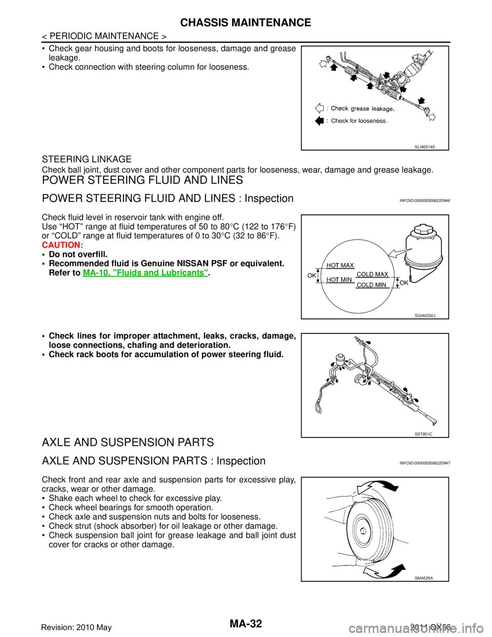
Check gear housing and boots for looseness, damage and greaseleakage.
Check connection with steering column for looseness.
STEERING LINKAGE
Check ball joint, dust cover and other component parts for looseness, wear, damage and grease leakage.
POWER STEERING FLUID AND LINES
POWER STEERING FLUID AND LINES : InspectionINFOID:0000000006220946
Check fluid level in reservoir tank with engine off.
Use “HOT” range at fluid temperatures of 50 to 80 °C (122 to 176 °F)
or “COLD” range at fluid temperatures of 0 to 30 °C (32 to 86 °F).
CAUTION:
Do not overfill.
Recommended fluid is Genuine NISSAN PSF or equivalent.
Refer to MA-10, "
Fluids and Lubricants".
Check lines for improper attachment, leaks, cracks, damage, loose connections, chaf ing and deterioration.
Check rack boots for accumulati on of power steering fluid.
AXLE AND SUSPENSION PARTS
AXLE AND SUSPENSION PARTS : InspectionINFOID:0000000006220947
Check front and rear axle and suspension parts for excessive play,
cracks, wear or other damage.
Shake each wheel to check for excessive play.
Check wheel bearings for smooth operation.
Check axle and suspension nuts and bolts for looseness.
Check strut (shock absorber) for oil leakage or other damage.
Check suspension ball joint for grease leakage and ball joint dust
cover for cracks or other damage.
SLIA0014E
SGIA0232J
SST851C
SMA525A
Revision: 2010 May2011 QX56
Page 4266 of 5598

REAR SHOCK ABSORBERRSU-11
< REMOVAL AND INSTALLATION >
C
DF
G H
I
J
K L
M A
B
RSU
N
O P
Inadvertent piping removal causes fluid to splatter.
2. Remove tires with power tool. Refer to WT-64, "
Removal and Installation".
3. Remove height sensor from rear lower link (right side). Refer to EXL-136, "
Removal and Installation".
4. Remove vehicle height sensor from rear lower link (left side). Refer to SCS-98, "
Removal and Installa-
tion".
5. Remove air tube from shock absorber assembly. Refer to SCS-95, "
Removal and Installation".
6. Remove middle tube assembly from shock absorber assembly. (With HBMC) Refer to SCS-44, "
REAR
TUBE ASSEMBLY : Removal and Installation".
7. Remove shock absorber mounting bolt (lower side).
8. Remove piston rod lock nut.
9. Remove bracket, bushings, and shock absorber. (With HBMC)
10. Remove washers, bushings, and shock absorber. (Without HBMC)
11. Perform inspection after removal. Refer to RSU-11, "
Inspection and Adjustment".
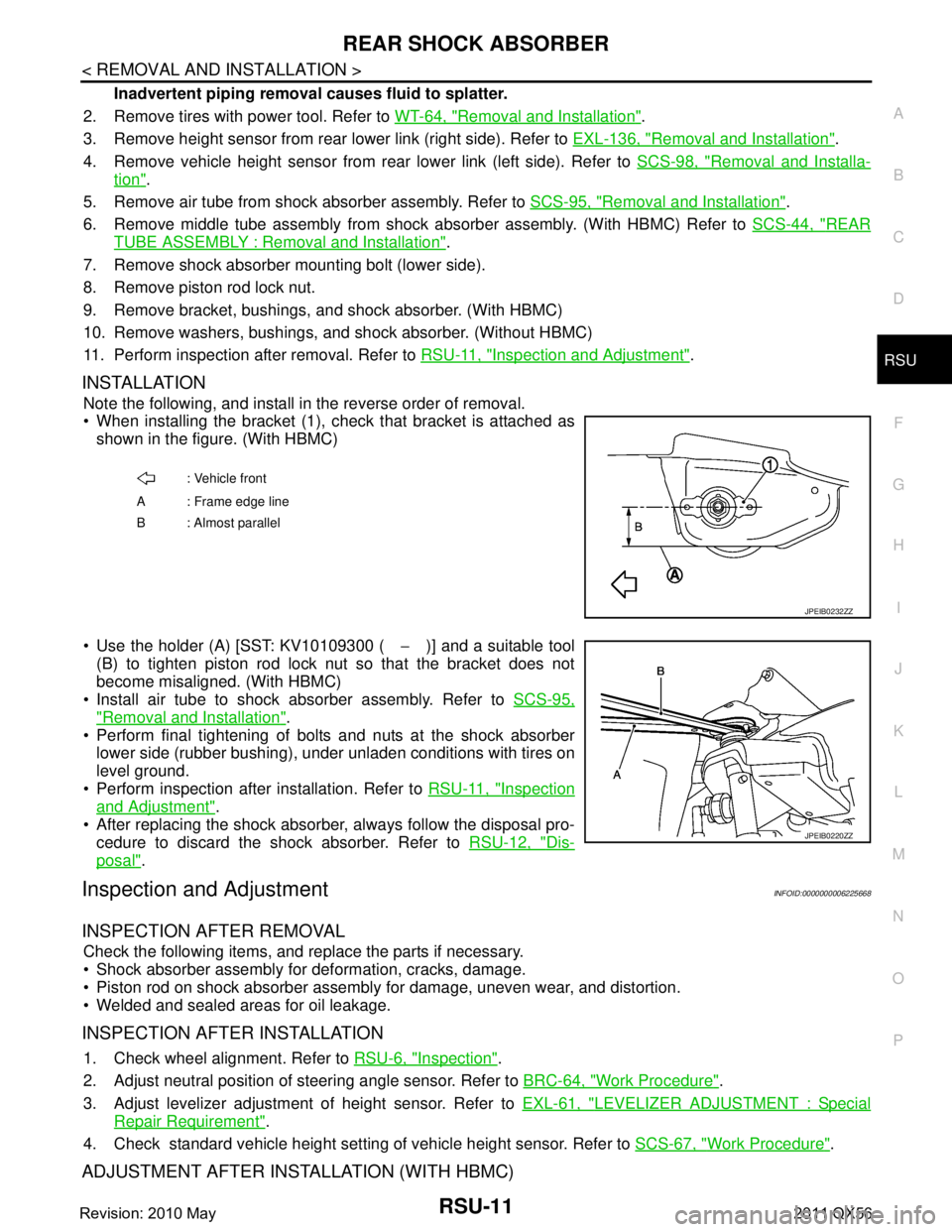
INSTALLATION
Note the following, and install in the reverse order of removal.
When installing the bracket (1), check that bracket is attached as
shown in the figure. (With HBMC)
Use the holder (A) [SST: KV10109300 ( −)] and a suitable tool
(B) to tighten piston rod lock nut so that the bracket does not
become misaligned. (With HBMC)
Install air tube to shock absorber assembly. Refer to SCS-95,
"Removal and Installation".
Perform final tightening of bolts and nuts at the shock absorber
lower side (rubber bushing), under unladen conditions with tires on
level ground.
Perform inspection after installation. Refer to RSU-11, "
Inspection
and Adjustment".
After replacing the shock absorber, always follow the disposal pro- cedure to discard the shock absorber. Refer to RSU-12, "
Dis-
posal".
Inspection and AdjustmentINFOID:0000000006225668
INSPECTION AFTER REMOVAL
Check the following items, and replace the parts if necessary.
Shock absorber assembly for deformation, cracks, damage.
Piston rod on shock absorber assembly for damage, uneven wear, and distortion.
Welded and sealed areas for oil leakage.
INSPECTION AFTER INSTALLATION
1. Check wheel alignment. Refer to RSU-6, "Inspection".
2. Adjust neutral position of steering angle sensor. Refer to BRC-64, "
Work Procedure".
3. Adjust levelizer adjustment of height sensor. Refer to EXL-61, "
LEVELIZER ADJUSTMENT : Special
Repair Requirement".
4. Check standard vehicle height setting of vehicle height sensor. Refer to SCS-67, "
Work Procedure".
ADJUSTMENT AFTER INSTALLATION (WITH HBMC)
: Vehicle front
A : Frame edge line
B: Almost parallel
JPEIB0232ZZ
JPEIB0220ZZ
Revision: 2010 May2011 QX56
Page 4988 of 5598

ST-1
STEERING
C
DE
F
H I
J
K L
M
SECTION ST
A
B
ST
N
O P
CONTENTS
STEERING SYSTEM
PRECAUTION ................ ...............................3
PRECAUTIONS .............................................. .....3
Precaution for Supplemental Restraint System
(SRS) "AIR BAG" and "SEAT BELT PRE-TEN-
SIONER" ............................................................. ......
3
Precaution Necessary for Steering Wheel Rota-
tion after Battery Disconnect .....................................
3
Service Notice or Precautions for Steering System
......
4
PREPARATION ............................................5
PREPARATION .............................................. .....5
Special Service Tools .......................................... ......5
Commercial Service Tools ........................................6
SYSTEM DESCRIPTION ..............................7
COMPONENT PARTS ................................... .....7
Component Parts Location (Heated Steering
Wheel) ................................................................. ......
7
Component Description (Heated Steering Wheel) ......7
Heated Steering Wheel .............................................7
Heated Steering Wheel Switch .................................8
Heated Steering Wheel Relay ...................................8
SYSTEM ..............................................................9
System Description (Heated Steering Wheel) ..... ......9
WIRING DIAGRAM ......................................10
HEATED STEERING WHEEL ........................ ....10
Wiring Diagram ................................................... ....10
BASIC INSPECTION ...................................13
DIAGNOSIS AND REPAIR WORK FLOW .... ....13
WorkFlow (Heated Steering Wheel) .................... ....13
STEERING WHEEL ............................................14
Inspection ............................................................ ....14
DTC/CIRCUIT DIAGNOSIS .........................16
HEATED STEERING WHEEL SYSTEM ...........16
Component Function Check ................................ ....16
Diagnosis Procedure ...............................................16
Component Inspection (Heated Steering Wheel) ....18
Component Inspection (Heated Steering Wheel
Relay) ......................................................................
19
HEATED STEERING WHEEL SWITCH INDI-
CATOR LAMP ...................................................
20
Component Function Check ....................................20
Diagnosis Procedure ...............................................20
Component Inspection (Heated Steering Wheel
Relay) ......................................................................
22
SYMPTOM DIAGNOSIS ..............................23
HEATED STEERING WHEEL SYSTEM DOES
NOT ACTIVATE ................................................
23
Description ........................................................... ....23
Diagnosis Procedure ...............................................23
HEATED STEERING WHEEL SWITCH INDI-
CATOR LAMP DOES NOT TURN ON ..............
26
Description ...............................................................26
Diagnosis Procedure ...............................................26
NOISE, VIBRATION AND HARSHNESS
(NVH) TROUBLESHOOTING ...........................
29
NVH Troubleshooting Chart ....................................29
PERIODIC MAINTENANCE ........................30
POWER STEERING FLUID ..............................30
Inspection ............................................................ ....30
STEERING WHEEL ..........................................32
Inspection ................................................................32
REMOVAL AND INSTALLATION ...............33
Revision: 2010 May2011 QX56