engine oil INFINITI QX56 2011 Factory Service Manual
[x] Cancel search | Manufacturer: INFINITI, Model Year: 2011, Model line: QX56, Model: INFINITI QX56 2011Pages: 5598, PDF Size: 94.53 MB
Page 5 of 5598

QUICK REFERENCE CHART QX56
BRAKE PEDAL
Unit : mm (in)
FRONT DISK BRAKE
Unit : mm (in)
REAR DISK BRAKE
Unit : mm (in)
REFILL CAPACITIESELS00040
Item Standard
Brake pedal height 168.5 (6.63) – 178.5 (7.03)
Depressed brake pedal height
[Depressing 490 N (50 kg, 110 lb) while turning the engine ON] 100 (3.94) or more
Item Limit
Brake pad Wear thickness 1.5 (0.059)
Disc rotor Wear thickness 28.5 (1.122)
Thickness variation (measured at 8 positions) 0.015 (0.0006)
Runout (with it attached to the vehicle) 0.053 (0.0021)
Item Limit
Brake pad Wear thickness 2.0 (0.079)
Disc rotor Wear thickness 18.0 (0.709)
Thickness variation (measured at 8 positions) 0.015 (0.0006)
Runout (with it attached to the vehicle) 0.05 (0.0020)
UNIT
Liter US measure
Fuel tank 98.4 26 gal
Engine Coolant ( With reservoir tank ) at MAX level 14.9 15-6/8 qt
Engine oil Drain and refill
With oil filter change 6.5 6-7/8 qt
Without oil filter change 6.2 6-4/8 qt
Dry engine (Overhaul) 7.6 8 qt
Transmission 10.0 10-5/8 qt
Transfer 1.5 3-1/8 pt
Final drive Front 0.75 1-5/8 pt
Rear 1.75 3-3/4 pt
Power steering system 1.0 7/8 qt
Air conditioning system Compressor oil 0.21 7.1 fl oz
Refrigerant 1.05 kg 2.32 lb
2011
Page 480 of 5598
BR-10
< PERIODIC MAINTENANCE >
BRAKE FLUID
BRAKE FLUID
InspectionINFOID:0000000006222463
BRAKE FLUID LEVEL
Check that the fluid level in the reservoir tank is within the specified range (MAX – MIN lines).
CAUTION:
Turn OFF the ignition switch an d depress the brake pedal 20 times or more to check brake fluid level.
NOTE:
Since brake fluid is in the accumulator in pressurized condition, the reservoir tank brake fluid level should be
lower than the MAX line.
Visually check for any brake fluid leakage around the reservoir tank.
Check the brake system for any leakage if the fl uid level is extremely low (lower than MIN).
Check the brake system for fluid leakage if the warn ing lamp remains illuminated even after the parking
brake is released.
Check the reservoir tank for the mixing of foreign matter (e.g. dust) and oils other than brake fluid.
BRAKE LINE
1. Check brake line (tubes and hoses) for cracks, deterioration or other damage. Replace any damaged
parts.
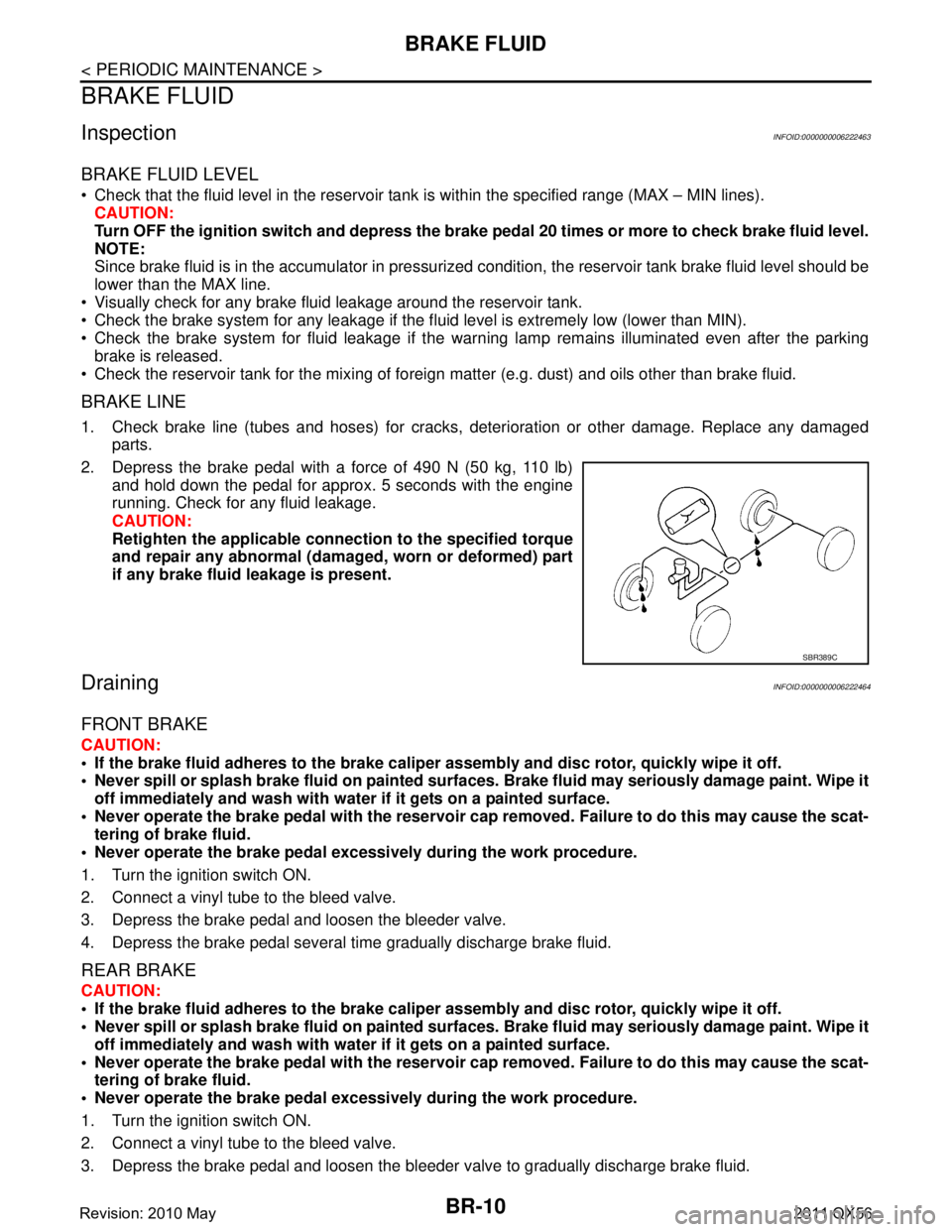
2. Depress the brake pedal with a force of 490 N (50 kg, 110 lb) and hold down the pedal for approx. 5 seconds with the engine
running. Check for any fluid leakage.
CAUTION:
Retighten the applicable conn ection to the specified torque
and repair any abnormal (damag ed, worn or deformed) part
if any brake fluid leakage is present.
DrainingINFOID:0000000006222464
FRONT BRAKE
CAUTION:
If the brake fluid adheres to the brake caliper assembly and disc rotor, quickly wipe it off.
Never spill or splash brake fluid on painted surfaces. Brake fluid may seriously damage paint. Wipe it
off immediately and wash with wate r if it gets on a painted surface.
Never operate the brake pedal with the reservoir cap removed. Failure to do this may cause the scat-
tering of brake fluid.
Never operate the brake pedal excessively during the work procedure.
1. Turn the ignition switch ON.
2. Connect a vinyl tube to the bleed valve.
3. Depress the brake pedal and loosen the bleeder valve.
4. Depress the brake pedal several time gradually discharge brake fluid.
REAR BRAKE
CAUTION:
If the brake fluid adheres to the brake caliper assembly and disc rotor, quickly wipe it off.
Never spill or splash brake fluid on painted surfaces. Brake fluid may seriously damage paint. Wipe it
off immediately and wash with wate r if it gets on a painted surface.
Never operate the brake pedal with the reservoir cap removed. Failure to do this may cause the scat- tering of brake fluid.
Never operate the brake pedal excessively during the work procedure.
1. Turn the ignition switch ON.
2. Connect a vinyl tube to the bleed valve.
3. Depress the brake pedal and loosen the bleeder valve to gradually discharge brake fluid.
SBR389C
Revision: 2010 May2011 QX56
Page 523 of 5598
![INFINITI QX56 2011 Factory Service Manual
BRC-6
< PRECAUTION >[WITH VDC]
PRECAUTIONS
5. When the repair work is completed, re-connect bot
h battery cables. With the brake pedal released, turn
the push-button ignition switch from ACC position INFINITI QX56 2011 Factory Service Manual
BRC-6
< PRECAUTION >[WITH VDC]
PRECAUTIONS
5. When the repair work is completed, re-connect bot
h battery cables. With the brake pedal released, turn
the push-button ignition switch from ACC position](/img/42/57033/w960_57033-522.png)
BRC-6
< PRECAUTION >[WITH VDC]
PRECAUTIONS
5. When the repair work is completed, re-connect bot
h battery cables. With the brake pedal released, turn
the push-button ignition switch from ACC position to ON position, then to LOCK position. (The steering
wheel will lock when the push-button igniti on switch is turned to LOCK position.)
6. Perform self-diagnosis check of all control units using CONSULT-III.
Precaution for Procedure without Cowl Top CoverINFOID:0000000006228176
When performing the procedure after removing cowl top cover, cover
the lower end of windshield with urethane, etc.
Precaution for Brake SystemINFOID:0000000006222556
WARNING:
Clean any dust from the front brake and rear brake using a vacuum dust collector. Never blow by com-
pressed air.
Brake fluid use refer to MA-10, "
Fluids and Lubricants".
Never reuse drained brake fluid.
Never spill or splash brake fluid on painted surfaces. Brake fluid may seriously damage paint. Wipe it off
immediately and wash with water if it gets on a painted surface.
Always confirm the specified tightening torque when installing the brake pipes.
After pressing the brake pedal more deeply or harder t han normal driving, such as air bleeding, check each
item of brake pedal. Adjust brake pedal if it is outside the standard value.
Never use mineral oils such as gasoline or light oil to clean. They may damage rubber parts and cause
improper operation.
Always loosen the brake tube flar e nut with a flare nut wrench.
Tighten the brake tube flare nut to the specified torque with a crow-
foot (A) and torque wrench (B).
Always connect the battery terminal when moving the vehicle.
Turn the ignition switch OFF and disconnect the ABS actuator and
electric unit (control unit) harness connector or the battery negative
terminal before performing the work.
Check that no brake fluid leakage is present after replacing the parts.
Precaution for Brak e Control SystemINFOID:0000000006222557
Slight vibrations are felt on the brake pedal and the operation noises occur, when VDC function, TCS func-
tion, ABS function, EBD function, hill start assist function or brake limited slip differential (BLSD) function
operates. This is not a malfunction because it is caus ed by VDC function, TCS function, ABS function, EBD
function, hill start assist function or brake limited sl ip differential (BLSD) function that is normally operated.
When starting engine or when starting vehicle just after starting engine, brake pedal may vibrate or motor
operating noise may be heard from engine compartment. This is normal condition.
Brake stopping distance may become longer than models without ABS function depending on the road con-
ditions, when ABS function is operated on slippery r oad like rough road, gravel road or snowy road.
When a malfunction is indicated, always collect info rmation from the customer about conditions of occur-
rence, estimate cause and perform operation. Check brake booster operation, brake fluid level and brake
fluid leakage, as well as electrical system.
The optimum performance is achieved by control for V DC function, TCS function, ABS function, EBD func-
tion, hill start assist function or brake limited slip di fferential (BLSD) function when all of brakes, suspensions
PIIB3706J
JPFIA0001ZZ
Revision: 2010 May2011 QX56
Page 807 of 5598
![INFINITI QX56 2011 Factory Service Manual
CCS-72
< BASIC INSPECTION >[ICC]
LASER BEAM AIMING ADJUSTMENT
LASER BEAM AIMING ADJUSTMENT
DescriptionINFOID:0000000006224293
OUTLINE OF LASER BEAM AIMING ADJUSTMENT
Always adjust the laser beam aimi INFINITI QX56 2011 Factory Service Manual
CCS-72
< BASIC INSPECTION >[ICC]
LASER BEAM AIMING ADJUSTMENT
LASER BEAM AIMING ADJUSTMENT
DescriptionINFOID:0000000006224293
OUTLINE OF LASER BEAM AIMING ADJUSTMENT
Always adjust the laser beam aimi](/img/42/57033/w960_57033-806.png)
CCS-72
< BASIC INSPECTION >[ICC]
LASER BEAM AIMING ADJUSTMENT
LASER BEAM AIMING ADJUSTMENT
DescriptionINFOID:0000000006224293
OUTLINE OF LASER BEAM AIMING ADJUSTMENT
Always adjust the laser beam aiming after removing and installing or replacing the ICC sensor.
CAUTION:
The system does not operate normally
unless the laser beam aiming adjustment is performed. Always
perform it.
1. Set the ICC target board [SST: KV99110100 (J-45718)] to the correct position in front of the vehicle.
2. Set the laser beam aiming mode (“LASER BEAM AD JUST” on “Work support”) with CONSULT-III, and
then perform the adjustment according to the displa y. (Manually turn the up-down direction adjusting
screw for vertical adjustment. ICC sensor adjusts the automatic aiming for the horizontal direction.)
CAUTIONARY POINT FOR LASER BEAM AIMING ADJUSTMENT
CAUTION:
For laser beam aiming adjustment, choose a level location where a view can be obtained without any
obstruction as far as 12 m (39 ft) or more in the forward direction.
Adjust laser beam aiming for 5 second s or more after starting engine.
Adjust the laser beam aiming with CONSULT-III. (The laser beam aiming cannot be adjusted without
CONSULT-III.)
Never enter the vehicle during laser beam aiming adjustment.
Never look directly into the laser beam sour ce (ICC sensor body window) during laser beam aiming
adjustment.
Laser beam aiming adjustment is performed at idle. At this time, turn the headlamps OFF.
Work Procedure (Preparation)INFOID:0000000006224294
1.ADVANCE PREPARATION FOR LASER BEAM AIMING ADJUSTMENT
1. Adjust all tire pressure to the specified value.
2. Empty the vehicle. (Remove any luggage from the passenger compartment, luggage room, etc.)
3. Shift the selector lever to “P” pos ition, and release the parking brake.
4. Fully fill the fuel tank, and then check that t he coolant and oils are filled up to correct level.
5. Clean off the ICC sensor body window with a soft cloth.
>> Go to CCS-72, "
Work Procedure (Setting The ICC Tar-
get Board)".
Work Procedure (Setting The ICC Target Board)INFOID:0000000006224295
DESCRIPTION
Accurate adjustment of the laser beam requires t hat the ICC target board be accurately positioned.
CAUTION:
If the laser beam is adjusted with the ICC target board in the incorrect position, the ICC system does
not function normally.
1.ICC TARGET BOARD HEIGHT ADJUSTMENT
1 : ICC sensor
JSOIA0372ZZ
Revision: 2010 May2011 QX56
Page 939 of 5598

CHG-26
< REMOVAL AND INSTALLATION >
ALTERNATOR
Type: A002TX1491
Removal and InstallationINFOID:0000000006274878
REMOVAL
1. Disconnect the battery cable from the negative terminal. Refer to PG-164, "Removal and Installation".
2. Remove front under cover. Refer to EXT-25, "
Removal and Installation".
3. Remove drive belt. Refer to EM-20, "
Removal and Installation".
4. Disconnect engine oil pressure switch connector (A) and alter- nator connector (B).
5. Remove harness bracket bolt (C).
6. Remove “B” terminal nut (D) and disconnect “B” terminal har- ness.
JMMIA0363GB
1. Rear bearing 2. Rotor assembly 3. Retainer
4. Front bearing 5. Front bracket assembly 6. Pulley
7. Pulley nut 8. Stator assembly 9. IC voltage regulator assembly
10. Diode assembly 11. Rear bracket assembly 12. Terminal set
Refer to GI-4, "
Components" for symbols in the figure.
JMMIA0364ZZ
Revision: 2010 May2011 QX56
Page 953 of 5598
RADIATORCO-11
< PERIODIC MAINTENANCE >
C
DE
F
G H
I
J
K L
M A
CO
NP
O
RADIATOR
RESERVOIR TANK CAP
RESERVOIR TANK CAP : InspectionINFOID:0000000006289661
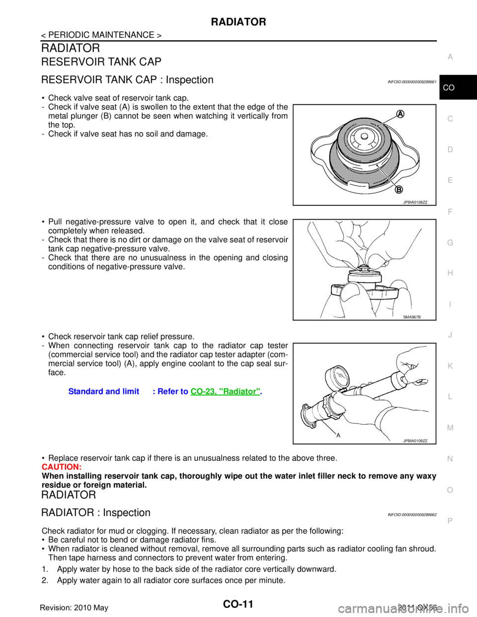
Check valve seat of reservoir tank cap.
- Check if valve seat (A) is swollen to the extent that the edge of the
metal plunger (B) cannot be seen when watching it vertically from
the top.
- Check if valve seat has no soil and damage.
Pull negative-pressure valve to open it, and check that it close completely when released.
- Check that there is no dirt or dam age on the valve seat of reservoir
tank cap negative-pressure valve.
- Check that there are no unusualness in the opening and closing conditions of negative-pressure valve.
Check reservoir tank cap relief pressure.
- When connecting reservoir tank cap to the radiator cap tester (commercial service tool) and the r adiator cap tester adapter (com-
mercial service tool) (A), apply engine coolant to the cap seal sur-
face.
Replace reservoir tank cap if there is an unusualness related to the above three.
CAUTION:
When installing reservoir tank cap , thoroughly wipe out the water inlet filler neck to remove any waxy
residue or foreign material.
RADIATOR
RADIATOR : InspectionINFOID:0000000006289662
Check radiator for mud or clogging. If neces sary, clean radiator as per the following:
Be careful not to bend or damage radiator fins.
When radiator is cleaned without removal, remove all surrounding parts such as radiator cooling fan shroud. Then tape harness and connectors to prevent water from entering.
1. Apply water by hose to the back side of the radiator core vertically downward.
2. Apply water again to all radiator core surfaces once per minute.
JPBIA0108ZZ
SMA967B
Standard and limit : Refer to CO-23, "Radiator".
JPBIA0109ZZ
Revision: 2010 May2011 QX56
Page 959 of 5598
COOLING FANCO-17
< REMOVAL AND INSTALLATION >
C
DE
F
G H
I
J
K L
M A
CO
NP
O
13. Remove the fan bracket, refer to following.
Disconnect A/C compressor harness connector. Refer to HA-30, "
Exploded View".
Remove A/C compressor mounting bolt. Refer to HA-30, "
Exploded View".
Remove fan bracket mounting bolt.
INSTALLATION
Installation is in the reverse order of removal.
InspectionINFOID:0000000006289668
INSPECTION AFTER REMOVAL
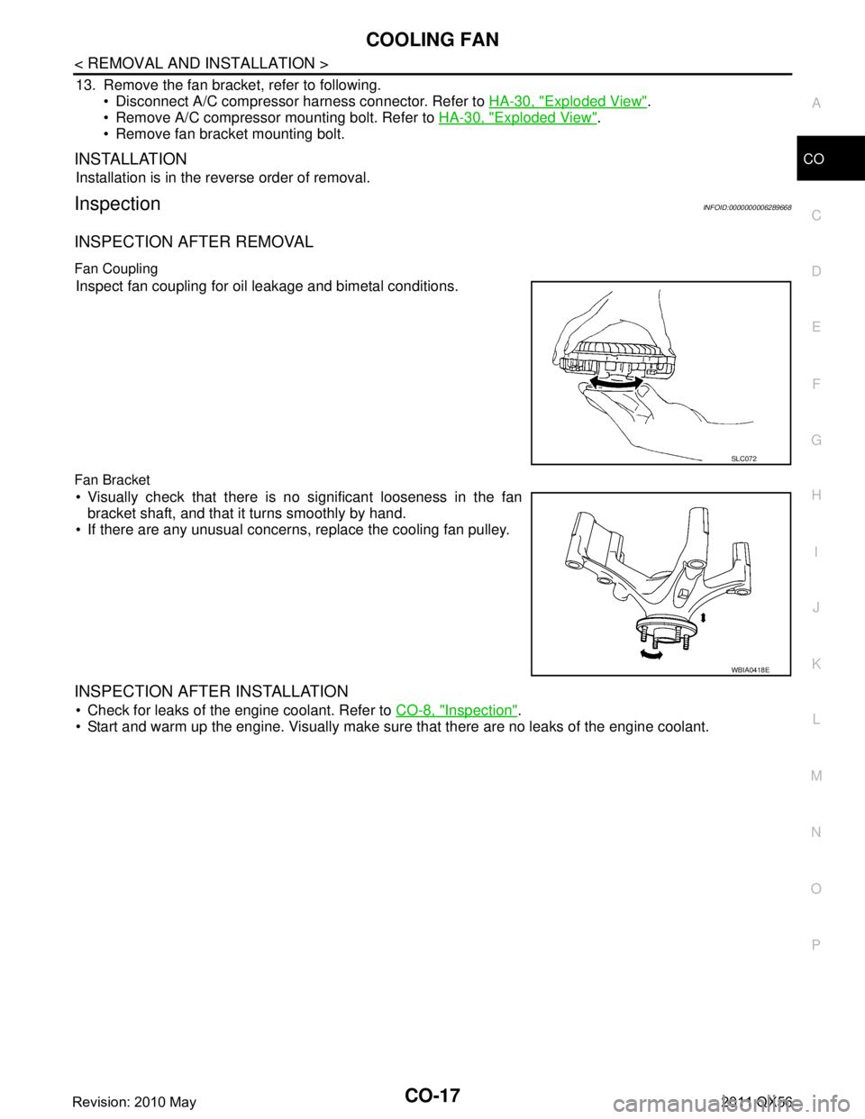
Fan Coupling
Inspect fan coupling for oil leakage and bimetal conditions.
Fan Bracket
Visually check that there is no significant looseness in the fan bracket shaft, and that it turns smoothly by hand.
If there are any unusual concerns, replace the cooling fan pulley.
INSPECTION AFTER INSTALLATION
Check for leaks of the engine coolant. Refer to CO-8, "Inspection".
Start and warm up the engine. Visually make sure that there are no leaks of the engine coolant.
SLC072
WBIA0418E
Revision: 2010 May2011 QX56
Page 1305 of 5598
![INFINITI QX56 2011 Factory Service Manual
DAS-340
< BASIC INSPECTION >[LDW & LDP]
CAMERA AIMING ADJUSTMENT
CAMERA AIMING ADJUSTMENT
DescriptionINFOID:0000000006223734
Always adjust the camera aiming after removing
and installing or replacin INFINITI QX56 2011 Factory Service Manual
DAS-340
< BASIC INSPECTION >[LDW & LDP]
CAMERA AIMING ADJUSTMENT
CAMERA AIMING ADJUSTMENT
DescriptionINFOID:0000000006223734
Always adjust the camera aiming after removing
and installing or replacin](/img/42/57033/w960_57033-1304.png)
DAS-340
< BASIC INSPECTION >[LDW & LDP]
CAMERA AIMING ADJUSTMENT
CAMERA AIMING ADJUSTMENT
DescriptionINFOID:0000000006223734
Always adjust the camera aiming after removing
and installing or replacing the lane camera unit.
CAUTION:
Place the vehicle on level ground when th e camera aiming adjustment is operated.
Follow the CONSULT-III when performing the came ra aiming. (Camera aiming adjustment cannot be
operated without CONSULT-III.)
Work Procedure (Preparation)INFOID:0000000006223735
1.PERFORM SELF-DIAGNOSIS
Perform self-diagnosis of ADAS control unit and lane camera unit.
Is any DTC detected?
Except “C1B01”>>Perform diagnosis on the detected DTC and repair or replace the applicable item. Refer to
DAS-310, "
DTC Index" (ICC/ADAS) or DAS-316, "DTC Index" (LANE CAMERA).
“C1B01” or no DTC>>GO TO 2.
2.PREPARATION BEFORE CAMERA AIMING ADJUSTMENT
1. Perform pre-inspection for diagnosis. Refer to DAS-335, "
Inspection Procedure".
2. Adjust the tire pressure to the specified pressure value.
3. Maintain no-load in vehicle.
4. Check if coolant and engine oil are filled up to correct level and fuel tank is full.
5. Shift the selector lever to “P” position and release the parking brake.
6. Clean the windshield.
7. Completely clear off the instrument panel.
>> GO TO 3.
3. PREPARATION OF AIMING ADJUSTMENT JIG
Prepare the aiming adjustment jig according to the following procedure and the figure.
1. Print out the target mark attached in this service manual. Refer to DAS-343, "
Work Procedure (Target
Mark Sample)".
2. Stick a printed target mark on the board with a scotch tape or a piece of double-sided tape.
NOTE:
Use the board that peripheral area of the ta rget is monochrome such as a white-board.
Notice that the cross of the target is horizontal and vertical.
JPOIA0011ZZ
Revision: 2010 May2011 QX56
Page 1502 of 5598
DEF-10
< SYSTEM DESCRIPTION >
DIAGNOSIS SYSTEM (IPDM E/R)
DIAGNOSIS SYSTEM (IPDM E/R)
Diagnosis DescriptionINFOID:0000000006349776
AUTO ACTIVE TEST
Description
In auto active test, the IPDM E/R sends a drive signal to the following systems to check their operation.
Oil pressure warning lamp
Rear window defogger
Front wiper (LO, HI)
Parking lamp
License plate lamp
Tail lamp
Side marker lamp
Front fog lamp
Headlamp (LO, HI)
A/C compressor (magnet clutch)
Operation Procedure
CAUTION:
Never perform auto active test in the following conditions.
Engine is running.
CONSULT-III is connected.
1. Close the hood and lift the wiper arms from the windshield. (Prevent windshield damage due to wiper
operation)
NOTE:
When auto active test is performed with hood opened, sprinkle water on windshield beforehand.
2. Turn the ignition switch OFF.
3. Turn the ignition switch ON, and within 20 seconds, pr ess the driver door switch 10 times. Then turn the
ignition switch OFF.
CAUTION:
Close passenger door.
4. Turn the ignition switch ON within 10 seconds. Af ter that the horn sounds once and the auto active test
starts.
CAUTION:
Engine starts when igniti on switch is turned ON while brake pedal is depressed.
5. The oil pressure warning lamp starts blinking when the auto active test starts.
6. After a series of the following operations is repeated 3 times, auto active test is completed.
NOTE:
When auto active test has to be cancelled halfway through test, turn the ignition switch OFF.
When auto active test is not activated, door swit ch may be the cause. Check door switch. Refer to DLK-117,
"ComponentFunctionCheck".
Inspection in Auto Active Test
When auto active test is actuated, the following operation sequence is repeated 3 times.
Operation
sequence Inspection location Operation
1 Oil pressure warning lamp Blinks continuously during operation of auto active test
2 Rear window defogger 10 seconds
3 Front wiper LO for 5 seconds → HI for 5 seconds
4 Parking lamp
License plate lamp
Tail lamp
Side marker lamp
Front fog lamp 10 seconds
Revision: 2010 May2011 QX56
Page 1788 of 5598
DLK-252
< REMOVAL AND INSTALLATION >
CAB MOUNTING INSULATOR
Drain brake fluid from brake line. Refer to BR-10, "Draining".
Release fuel pressure. Refer to EC-153, "
Work Procedure".
Disconnect both battery cables. Refer to PG-164, "
Removal and Installation".
Drain engine coolant from radiator. Refer to CO-8, "
Draining".
Discharge refrigerant from A/C circuit. Refer to HA-20, "
Recycle Refrigerant".
Drain power steering fluid from reservoir tank.
4. Remove parts relating to connection of body assembly and frame assembly. Tire and wheel: Refer to WT-64, "
Removal and Installation" (with TPMS).
Front fender protector (LH and RH): Refer to EXT-23, "
FENDER PROTECTOR : Removal and Installa-
tion".
Front bumper: Refer to EXT-13, "
Removal and Installation".
Radiator core support upper: Refer to DLK-220, "
Removal and Installation".
Fan shroud: Refer to CO-16, "
Removal and Installation".
Battery and battery case: Refer to PG-164, "
Removal and Installation".
Air cleaner case (upper and lower): Refer to EM-27, "
Removal and Installation".
Engine cover: Refer to EM-25, "
Removal and Installation".
Rear wheel house protector (LH and RH): EXT-24, "
REAR WHEEL HOUSE PROTECTOR : Removal
and Installation".
Rear bumper: Refer to EXT-17, "
Removal and Installation".
Fuel filler tube: Remove to FL-8, "
Exploded View".
Spare tire
Towing hook bracket.
5. Separate parts relating to connection of body assembly and frame assembly. Vehicle front
Disconnect ICC sensor connector. (models with ICC) Refer to CCS-176, "
Removal and Installation".
Remove radiator upper hose and radiator lower hose from radiator assembly. Refer to CO-13,
"Exploded View".
Remove A/T fluid cooler hose B and A/T fluid cooler hose E from A/T fluid cooler tubes. Refer to TM-
202, "Exploded View".
Remove power steering return hose from oil cooler, and then power steering return hose clamp bolt from frame assembly. Refer to ST-54, "
Exploded View".
Remove power steering suction hose from reservoir tank. Refer to ST-54, "
Exploded View".
CAUTION:
Never spill power steering fluid in engine room.
Remove A/C low-presser flexible hose from A/C low-presser pipe. Refer to HA-35, "
LOW-PRESSURE
FLEXIBLE HOSE : Removal and Installation".
Remove A/C hi-presser flexible hose from condenser. Refer to HA-34, "
HIGH-PRESSURE FLEXIBLE
HOSE : Removal and Installation".
Remove all engine Control Harness connectors, har ness clips and others that are connected to the
body assembly side of the engine room. (engine room LH and RH side). Refer to PG-148, "
Engine Con-
trol Harness".
NOTE:
Separate harness connectors from ECM (engine control module). Refer to EC-10, "
General Precau-
tions".
CAUTION:
When pulling out harnesses, never damage harnesses or connectors.
After temporarily securing connectors, cover th em with vinyl or similar material to protect
against adhesion of foreign materials.
Disconnect engine room harness connectors and remo ve harness clips from engine assembly (engine
RH side). Refer to PG-146, "
Engine Room Harness".
Remove heater hoses from front water outlet tube (engine room RH side). Refer to HA-33, "
Exploded
View".
Disconnect front wheel sensor connectors (LH and RH). Refer to BRC-134, "
FRONT WHEEL SENSOR
: Exploded View".
Disconnect fuel feed tube and EVAP hos e (front wheel well LH side).
Remove steering lower shaft from steering gear side assembly. Refer to ST-37, "
Removal and Installa-
tion"
CAUTION:
Spiral cable may be cut if steering wheel turns while separating steering column assembly and
steering gear assembly.
Revision: 2010 May2011 QX56