radiator cap INFINITI QX56 2011 Factory User Guide
[x] Cancel search | Manufacturer: INFINITI, Model Year: 2011, Model line: QX56, Model: INFINITI QX56 2011Pages: 5598, PDF Size: 94.53 MB
Page 960 of 5598
CO-18
< REMOVAL AND INSTALLATION >
WATER PUMP
WATER PUMP
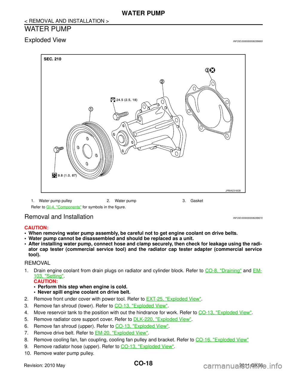
Exploded ViewINFOID:0000000006289669
Removal and InstallationINFOID:0000000006289670
CAUTION:
When removing water pump assembly, be careful not to get engine coolant on drive belts.
Water pump cannot be disassembled and should be replaced as a unit.
After installing water pump, co nnect hose and clamp securely, then check for leakage using the radi-
ator cap tester (commercial service tool) and the radiator cap tester adapter (commercial service
tool).
REMOVAL
1. Drain engine coolant from drain plugs on radiator and cylinder block. Refer to CO-8, "Draining" and EM-
103, "Setting".
CAUTION:
Perform this step when engine is cold.
Never spill engine coolant on drive belt.
2. Remove front under cover with power tool. Refer to EXT-25, "
Exploded View".
3. Remove fan shroud (lower). Refer to CO-13, "
Exploded View".
4. Move reservoir tank to the position with out the hindrance for work. Refer to CO-13, "
Exploded View".
5. Remove radiator core support cover. Refer to DLK-220, "
Exploded View".
6. Remove fan shroud (upper). Refer to CO-13, "
Exploded View".
7. Remove drive belt. Refer to EM-20, "
Exploded View".
8. Remove cooling fan, fan coupling, cooling fan pulley and bracket. Refer to CO-16, "
Exploded View"
9. Remove radiator hose (upper). Refer to CO-13, "Exploded View".
10. Remove water pump pulley.
1. Water pump pulley 2. Water pump 3. Gasket
Refer to GI-4, "
Components" for symbols in the figure.
JPBIA2316GB
Revision: 2010 May2011 QX56
Page 961 of 5598
WATER PUMPCO-19
< REMOVAL AND INSTALLATION >
C
DE
F
G H
I
J
K L
M A
CO
NP
O
11. Remove water pump. Refer to
CO-18, "Exploded View".
Engine coolant will leak from cylinder block, so have a receptacle ready under vehicle.
CAUTION:
Handle the water pump vane so that it does not contact any other parts.
Never disassemble water pump.
INSTALLATION
Install in the reverse order of removal.
InspectionINFOID:0000000006289671
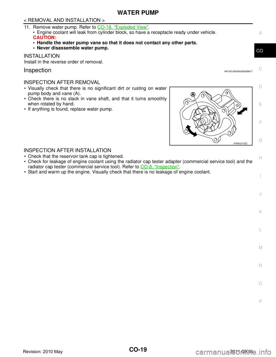
INSPECTION AFTER REMOVAL
Visually check that there is no significant dirt or rusting on water pump body and vane (A).
Check there is no slack in vane shaft, and that it turns smoothly when rotated by hand.
If anything is found, replace water pump.
INSPECTION AFTER INSTALLATION
Check that the reservoir tank cap is tightened.
Check for leakage of engine coolant using the radiator cap tester adapter (commercial service tool) and the
radiator cap tester (commercial service tool). Refer to CO-8, "
Inspection".
Start and warm up the engine. Visually check that there is no leakage of engine coolant.
JPBIA2315ZZ
Revision: 2010 May2011 QX56
Page 964 of 5598
CO-22
< REMOVAL AND INSTALLATION >
WATER INLET AND THERMOSTAT ASSEMBLY
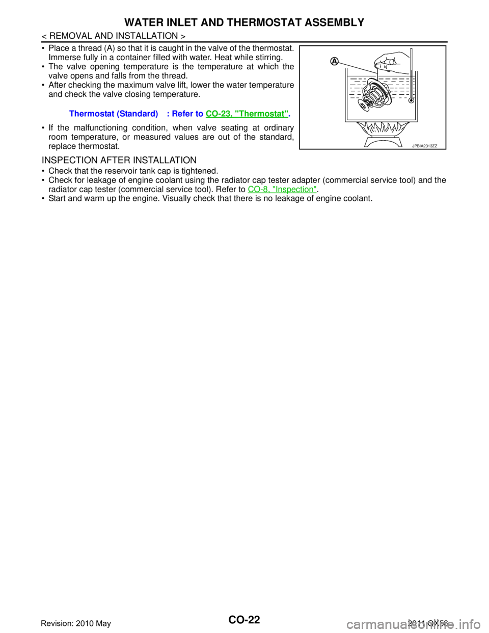
Place a thread (A) so that it is caught in the valve of the thermostat.Immerse fully in a container filled with water. Heat while stirring.
The valve opening temperature is the temperature at which the
valve opens and falls from the thread.
After checking the maximum valve lift, lower the water temperature and check the valve closing temperature.
If the malfunctioning condition, when valve seating at ordinary room temperature, or measured values are out of the standard,
replace thermostat.
INSPECTION AFTER INSTALLATION
Check that the reservoir tank cap is tightened.
Check for leakage of engine coolant using the radiator cap tester adapter (commercial service tool) and the
radiator cap tester (commercial service tool). Refer to CO-8, "
Inspection".
Start and warm up the engine. Visually chec k that there is no leakage of engine coolant.
Thermostat (Standard) : Refer to
CO-23, "
Thermostat".
JPBIA2313ZZ
Revision: 2010 May2011 QX56
Page 965 of 5598
SERVICE DATA AND SPECIFICATIONS (SDS)
CO-23
< SERVICE DATA AND SPECIFICATIONS (SDS)
C
D E
F
G H
I
J
K L
M A
CO
NP
O
SERVICE DATA AND SPECIFICATIONS (SDS)
SERVICE DATA AND SPECIFICATIONS (SDS)
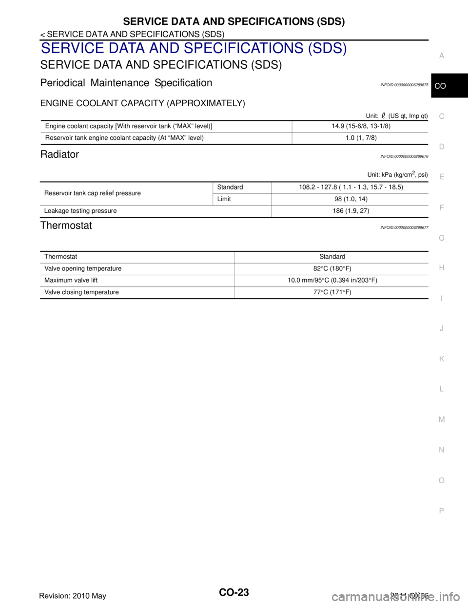
Periodical Maintenance SpecificationINFOID:0000000006289675
ENGINE COOLANT CAPACITY (APPROXIMATELY)
Unit: (US qt, Imp qt)
RadiatorINFOID:0000000006289676
Unit: kPa (kg/cm2, psi)
ThermostatINFOID:0000000006289677
Engine coolant capacity [With reservoir tank (“MAX” level)] 14.9 (15-6/8, 13-1/8)
Reservoir tank engine coolant capacity (At “MAX” level) 1.0 (1, 7/8)
Reservoir tank cap relief pressure
Standard 108.2 - 127.8 ( 1.1 - 1.3, 15.7 - 18.5)
Limit 98 (1.0, 14)
Leakage testing pressure 186 (1.9, 27)
ThermostatStandard
Valve opening temperature 82 °C (180 °F)
Maximum valve lift 10.0 mm/95 °C (0.394 in/203 °F)
Valve closing temperature 77 °C (171 °F)
Revision: 2010 May2011 QX56
Page 2424 of 5598
![INFINITI QX56 2011 Factory User Guide
EC-400
< DTC/CIRCUIT DIAGNOSIS >[VK56VD]
P1217 ENGINE OVER TEMPERATURE
P1217 ENGINE OVER TEMPERATURE
DTC LogicINFOID:0000000006217909
DTC DETECTION LOGIC
NOTE:
If DTC P1217 is displayed with DTC UX INFINITI QX56 2011 Factory User Guide
EC-400
< DTC/CIRCUIT DIAGNOSIS >[VK56VD]
P1217 ENGINE OVER TEMPERATURE
P1217 ENGINE OVER TEMPERATURE
DTC LogicINFOID:0000000006217909
DTC DETECTION LOGIC
NOTE:
If DTC P1217 is displayed with DTC UX](/img/42/57033/w960_57033-2423.png)
EC-400
< DTC/CIRCUIT DIAGNOSIS >[VK56VD]
P1217 ENGINE OVER TEMPERATURE
P1217 ENGINE OVER TEMPERATURE
DTC LogicINFOID:0000000006217909
DTC DETECTION LOGIC
NOTE:
If DTC P1217 is displayed with DTC UXXXX, perform the trouble diagnosis for DTC UXXXX.
If DTC P1217 is displayed with DTC P0607, perfo rm the trouble diagnosis for DTC P0607. Refer to
EC-378, "
DTC Logic".
If DTC P1217 is displayed with DTC P0527, perfo rm the trouble diagnosis for DTC P0527. Refer to
EC-367, "
DTC Logic".
If the cooling fan or any of other components in the cooling system has a malfunction, engine coolant temper-
ature increases.
When the engine coolant temperature reaches an abnorma lly high temperature condition, a malfunction is
indicated.
CAUTION:
When a malfunction is indicated, al ways replace the coolant. Refer to CO-8, "
Draining" and CO-9,
"Refilling". Also, replace the engine oil. Refer to LU-8, "Draining" and LU-8, "Refilling".
1. Fill radiator with coolant up to specified level with a filling speed of 2 liters per minute. Always use
coolant with the proper mixture ratio. Refer to MA-11, "
Anti-Freeze Coolant Mixture Ratio".
2. After refilling coolant, run engine to en sure that no water-flow noise is emitted.
DTC CONFIRMATION PROCEDURE
1.PERFORM COMPONENT FUNCTION CHECK
Perform component function check. Refer to EC-400, "
Component Function Check".
NOTE:
Use component function check to check the overall functi on of the cooling fan. During this check, a DTC might
not be confirmed.
Is the inspection result normal?
YES >> INSPECTION END
NO >> Go to EC-401, "
Diagnosis Procedure".
Component Function CheckINFOID:0000000006217910
1.PERFORM COMPONENT FUNCTION CHECK-I
WARNING:
Never remove the reservoir tank cap when the engi ne is hot. Serious burns could be caused by high
pressure fluid escaping from the radiator.
Wrap a thick cloth around cap. Carefully remove the cap by turning it a quarter turn to allow built-up
pressure to escape. Then turn the cap all the way off.
DTC No. Trouble diagnosis name DTC detecting condition Possible cause
P1217 Engine over temperature
(Overheat) Cooling fan does not operate properly
(Overheat).
Cooling fan system does not operate properly (Overheat).
Engine coolant is not within the specified quantity. Harness or connectors
(The cooling fan circuit is open or shorted.)
IPDM E/R
Electrically-controlled cooling fan coupling
Cooling fan speed sensor
Radiator hose
Radiator
Reservoir tank cap
Water pump
Thermostat
Revision: 2010 May2011 QX56
Page 2426 of 5598
![INFINITI QX56 2011 Factory User Guide
EC-402
< DTC/CIRCUIT DIAGNOSIS >[VK56VD]
P1217 ENGINE OVER TEMPERATURE
YES >> GO TO 3.
NO >> GO TO 4.
3.CHECK ENGINE COOLANT LEAKAGE-II
Check the following for leakage.
Hose
Radiator
Water pump
INFINITI QX56 2011 Factory User Guide
EC-402
< DTC/CIRCUIT DIAGNOSIS >[VK56VD]
P1217 ENGINE OVER TEMPERATURE
YES >> GO TO 3.
NO >> GO TO 4.
3.CHECK ENGINE COOLANT LEAKAGE-II
Check the following for leakage.
Hose
Radiator
Water pump](/img/42/57033/w960_57033-2425.png)
EC-402
< DTC/CIRCUIT DIAGNOSIS >[VK56VD]
P1217 ENGINE OVER TEMPERATURE
YES >> GO TO 3.
NO >> GO TO 4.
3.CHECK ENGINE COOLANT LEAKAGE-II
Check the following for leakage.
Hose
Radiator
Water pump
>> Repair or replace malfunctioning part.
4.CHECK RESERVOIR TANK CAP
Check reservoir tank cap. Refer to CO-11, "
RESERVOIR TANK CAP : Inspection".
Is the inspection result normal?
YES >> GO TO 5.
NO >> Replace reservoir tank cap.
5.CHECK THERMOSTAT
Check thermostat. Refer to CO-21, "
Inspection".
Is the inspection result normal?
YES >> GO TO 6.
NO >> Replace thermostat. Refer to CO-20, "
Removal and Installation".
6.CHECK ENGINE COOLANT TEMPERATURE SENSOR
Refer to EC-216, "
Component Inspection (Engine Coolant Temperature Sensor)".
Is the inspection result normal?
YES >> GO TO 7.
NO >> Replace engine coolant temperature sensor. Refer to EM-86, "
Exploded View".
7.CHECK MAIN 12 CAUSES
If the cause cannot be isolated, check the CO-6, "
TroubleshootingChart".
>> INSPECTION END
Revision: 2010 May2011 QX56
Page 2552 of 5598
![INFINITI QX56 2011 Factory User Guide
E C -528
< SYMPTOM DIAGNOSIS >[VK56VD]
ENGINE CONTROL SYSTEM SYMPTOMS
1 - 6: The numbers refer to the order of inspection.Lubrica-
tion
Oil pan/Oil strainer/Oil pump/Oil
filter/Oil gallery/Oil coole INFINITI QX56 2011 Factory User Guide
E C -528
< SYMPTOM DIAGNOSIS >[VK56VD]
ENGINE CONTROL SYSTEM SYMPTOMS
1 - 6: The numbers refer to the order of inspection.Lubrica-
tion
Oil pan/Oil strainer/Oil pump/Oil
filter/Oil gallery/Oil coole](/img/42/57033/w960_57033-2551.png)
E C -528
< SYMPTOM DIAGNOSIS >[VK56VD]
ENGINE CONTROL SYSTEM SYMPTOMS
1 - 6: The numbers refer to the order of inspection.Lubrica-
tion
Oil pan/Oil strainer/Oil pump/Oil
filter/Oil gallery/Oil cooler 55555 55 5 EM-56
EM-60
LU-9
LU-12
LU-14
Oil level (Low)/Filthy oil
LU-7
Cooling
Radiator/Hose/Radiator filler cap
55555 55 45 CO-11
CO-11
Thermostat 5
CO-21
Water pumpCO-19
Water galleryEM-115
Cooling fan
5CO-17
Coolant level (Low)/Contaminat-
ed coolant
CO-8
IVIS (INFINITI Vehicle Immobilizer System —
NATS)11
SEC-48
SYMPTOM
Reference
page
HARD/NO START/RESTART (EXCP. HA)
ENGINE STALL
HESITATION/SURGING/FLAT SPOT
SPARK KNOCK/DETONATION
LACK OF POWER/POOR ACCELERATION
HIGH IDLE/LOW IDLE
ROUGH IDLE/HUNTING
IDLING VIBRATION
SLOW/NO RETURN TO IDLE
OVERHEATS/WATER TEMPERATURE HIGH
EXCESSIVE FUEL CONSUMPTION
EXCESSIVE OIL CONSUMPTION
BATTERY DEAD (UNDER CHARGE)
Warranty symptom code AA AB AC AD AE AF AG AH AJ AK AL AM HA
Revision: 2010 May2011 QX56
Page 2992 of 5598
GI-28
< PRECAUTION >
PRECAUTIONS
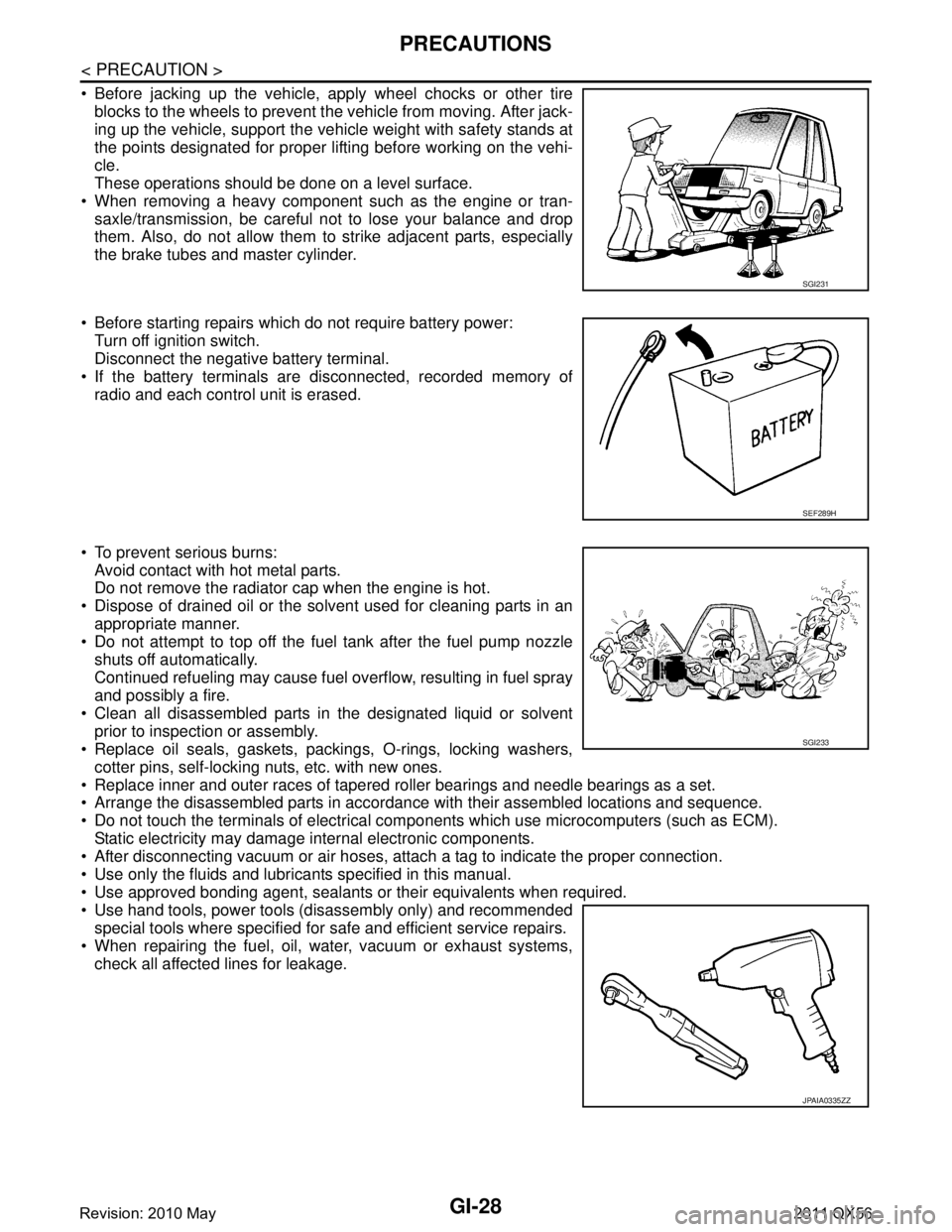
Before jacking up the vehicle, apply wheel chocks or other tireblocks to the wheels to prevent t he vehicle from moving. After jack-
ing up the vehicle, support the vehicle weight with safety stands at
the points designated for proper lifting before working on the vehi-
cle.
These operations should be done on a level surface.
When removing a heavy component such as the engine or tran- saxle/transmission, be careful not to lose your balance and drop
them. Also, do not allow them to strike adjacent parts, especially
the brake tubes and master cylinder.
Before starting repairs which do not require battery power: Turn off ignition switch.
Disconnect the negative battery terminal.
If the battery terminals are disconnected, recorded memory of
radio and each control unit is erased.
To prevent serious burns: Avoid contact with hot metal parts.
Do not remove the radiator cap when the engine is hot.
Dispose of drained oil or the solvent used for cleaning parts in an appropriate manner.
Do not attempt to top off the fuel tank after the fuel pump nozzle
shuts off automatically.
Continued refueling may cause fuel overflow, resulting in fuel spray
and possibly a fire.
Clean all disassembled parts in the designated liquid or solvent prior to inspection or assembly.
Replace oil seals, gaskets, packings, O-rings, locking washers,
cotter pins, self-locking nuts, etc. with new ones.
Replace inner and outer races of tapered roller bearings and needle bearings as a set.
Arrange the disassembled parts in accordance with their assembled locations and sequence.
Do not touch the terminals of electrical com ponents which use microcomputers (such as ECM).
Static electricity may damage internal electronic components.
After disconnecting vacuum or air hoses, atta ch a tag to indicate the proper connection.
Use only the fluids and lubricants specified in this manual.
Use approved bonding agent, sealants or their equivalents when required.
Use hand tools, power tools (disassembly only) and recommended special tools where specified for safe and efficient service repairs.
When repairing the fuel, oil, water, vacuum or exhaust systems, check all affected lines for leakage.
SGI231
SEF289H
SGI233
JPAIA0335ZZ
Revision: 2010 May2011 QX56
Page 3094 of 5598

HA-38
< REMOVAL AND INSTALLATION >
CONDENSER
CONDENSER
Exploded ViewINFOID:0000000006276178
CONDENSER
CONDENSER : Removal and InstallationINFOID:0000000006276179
CAUTION:
Perform lubricant return operation before each refrigeration system disassembly. However, if a large
amount of refrigerant or lubrican t is detected, never perform lubricant return operation. Refer to HA-
22, "Perform Lubricant Return Operation".
REMOVAL
1. Use a refrigerant collecting equipment (for HF C-134a) to discharge the refrigerant. Refer to HA-20, "Recy-
cle Refrigerant".
2. Remove the radiator core support upper. Refer to DLK-220, "
Removal and Installation".
3. Remove steering oil cooler. Refer to ST-54, "
Exploded View".
4. Remove A/T fluid cooler. Refer to TM-202, "
Removal and Installation".
5. Remove mounting bolt, and then disconnect high-pressure flexible hose from condenser. CAUTION:
Cap or wrap the joint of the A/C piping and conden ser with suitable material such as vinyl tape to
avoid the entry of air.
6. Remove mounting bolt, and then disconnect high-pressure pipe from condenser. CAUTION:
Cap or wrap the joint of the A/C piping and conden ser with suitable material such as vinyl tape to
avoid the entry of air.
7. Remove mounting bolts, and then remove condenser from the vehicle. CAUTION:
Be careful not to damage core surface of condenser.
INSTALLATION
Note the following items, and install in the reverse order of removal.
1. Outlet pipe assembly 2. Refrigerant pressure sensor 3. O-ring
4. Pipe cover 5. Liquid tank pipe 1 6. Liquid tank pipe 2
7. Liquid tank bracket 8. Liquid tank 9. Inlet pipe assembly
10. Condenser
Refer to GI-4, "
Components" for symbols in the figure.
JMIIA0627GB
Revision: 2010 May2011 QX56
Page 3099 of 5598

A/C UNIT ASSEMBLYHA-43
< REMOVAL AND INSTALLATION >
C
DE
F
G H
J
K L
M A
B
HA
N
O P
Perform lubricant return operati on before each refrigeration system disassembly. However, if a large
amount of refrigerant or lubricant is detected, n ever perform lubricant return operation. Refer to HA-
22, "Perform Lubricant Return Operation".
REMOVAL
1. Use a refrigerant collecting equipment (for HF C-134a) to discharge the refrigerant. Refer to HA-20, "Recy-
cle Refrigerant". (If equipped)
2. Drain engine coolant from cooling system. Refer to CO-8, "
Draining".
3. Remove clamps, and then disconnect front heater outlet hose from heater pipe.
CAUTION:
Some coolant may spill when heater hoses are disconnected.
Close off the coolant inlet and outlet on the heater core (2 locations) with shop cloths.
4. Remove mounting bolt, and then disconnect low-pressure pipe and high-pressure pipe from expansion valve.
CAUTION:
Cap or wrap the joint of the A/C piping and expan sion valve with suitable material such as vinyl
tape to avoid the entry of air.
5. Remove instrument panel assembly. Refer to IP-14, "
Removal and Installation".
6. Remove steering column mounting bolt and nuts. Refer to ST-34, "
Removal and Installation".
7. Move steering column assembly to a position where it does not inhibit work.
8. Disconnect harness clips, harness connectors, ground bol ts and blackets from steering member, and then
move the vehicle harness to the position without hindrance for work.
9. Remove mounting nuts, and then remove instrument stay (RH and LH).
10. Remove A/C unit assembly mounting bolts.
11. Remove mounting bolts, and then remove steering member from the vehicle.
12. Disconnect drain hose from A/C unit assembly, and then remove A/C unit assembly from the vehicle.
13. Remove mounting bolts, and then disconnect heater & cooling unit and blower unitassembly.
INSTALLATION
Note the following items, and install in the reverse order of removal.
CAUTION:
Replace O-rings with new ones. Then apply compressor oil to them when installing.
Check for leakages when recharging refrigerant. Refer to HA-18, "
Leak Test".
NOTE:
Refer to CO-9, "
Refilling" when filling radiator with engine coolant.
EVAPORATOR
EVAPORATOR : Removal and InstallationINFOID:0000000006276184
REMOVAL
1. Remove heater & cooling unit assembly. Refer to HA-41, "Exploded View".
2. Remove heater core. Refer to HA-44, "
HEATER CORE : Removal and Installation".
3. Remove mounting screws, and then remove evaporator pipe cover.
4. Remove air mix door motor (RH). Refer to HAC-153, "
AIR MIX DOOR MOTOR : Removal and Installa-
tion".
5. Remove mounting screws, and then remove A/C cover.
6. Remove foot duct LH. Refer to VTL-11, "
FLOOR DUCT 1 : Removal and Installation".
7. Remove mounting screws, and then remove A/C lower case.
8. Remove intake sensor. Refer to HAC-150, "
Removal and Installation".
9. Remove evaporator assembly from heater & cooling unit assembly.
10. Remove mounting bolts, and then remove evaporator from evaporator assembly.
CAUTION:
Cap or wrap the joint of the evaporator and evaporat or pipe assembly with suitable material such as
vinyl tape to avoid the entry of air.
Revision: 2010 May2011 QX56