ECU INFINITI QX56 2011 Factory Owner's Manual
[x] Cancel search | Manufacturer: INFINITI, Model Year: 2011, Model line: QX56, Model: INFINITI QX56 2011Pages: 5598, PDF Size: 94.53 MB
Page 188 of 5598
AV-40
< SYSTEM DESCRIPTION >
DIAGNOSIS SYSTEM (AV CONTROL UNIT)
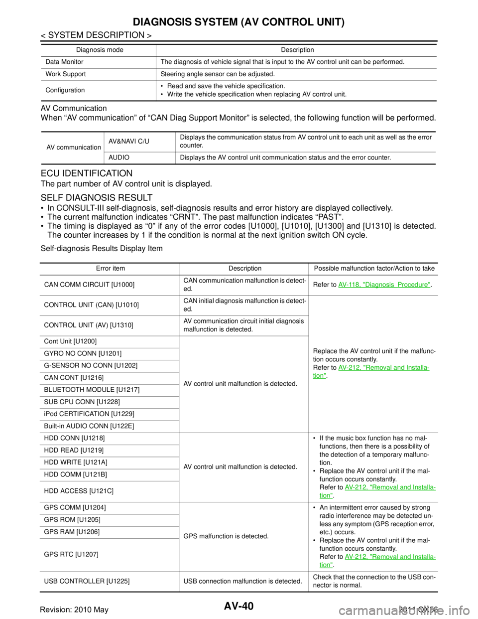
AV Communication
When “AV communication” of “CAN Diag Support Monitor” is selected, the f\
ollowing function will be performed.
ECU IDENTIFICATION
The part number of AV control unit is displayed.
SELF DIAGNOSIS RESULT
In CONSULT-III self-diagnosis, self-diagnosis results and error history are displayed collectively.
The current malfunction indicates “CRNT”. The past malfunction indicates “PAST”.
The timing is displayed as “0” if any of the e rror codes [U1000], [U1010], [U1300] and [U1310] is detected.
The counter increases by 1 if the condition is normal at the next ignition switch ON cycle.
Self-diagnosis Results Display Item
Data Monitor The diagnosis of vehicle signal that is input to the AV control unit can be performed.
Work Support Steering angle sensor can be adjusted.
Configuration Read and save the vehicle specification.
Write the vehicle specification when replacing AV control unit.
Diagnosis mode Description
AV communication
AV&NAVI C/U
Displays the communication status from AV control unit to each unit as well as the error
counter.
AUDIO Displays the AV control unit communication status and the error counter.
Error item Description Possible malfunction factor/Action to take
CAN COMM CIRCUIT [U1000] CAN communication malfunction is detect-
ed.Refer to
AV- 11 8 , "
DiagnosisProcedure".
CONTROL UNIT (CAN) [U1010] CAN initial diagnosis malfunction is detect-
ed.
Replace the AV control unit if the malfunc-
tion occurs constantly.
Refer to AV- 2 1 2 , "
Removal and Installa-
tion".
CONTROL UNIT (AV) [U1310]
AV communication circuit initial diagnosis
malfunction is detected.
Cont Unit [U1200]
AV control unit malfunction is detected.
GYRO NO CONN [U1201]
G-SENSOR NO CONN [U1202]
CAN CONT [U1216]
BLUETOOTH MODULE [U1217]
SUB CPU CONN [U1228]
iPod CERTIFICATION [U1229]
Built-in AUDIO CONN [U122E]
HDD CONN [U1218]
AV control unit malfunction is detected. If the music box function has no mal-
functions, then there is a possibility of
the detection of a temporary malfunc-
tion.
Replace the AV control unit if the mal- function occurs constantly.
Refer to AV- 2 1 2 , "
Removal and Installa-
tion".
HDD READ [U1219]
HDD WRITE [U121A]
HDD COMM [U121B]
HDD ACCESS [U121C]
GPS COMM [U1204]
GPS malfunction is detected. An intermittent error caused by strong
radio interference may be detected un-
less any symptom (GPS reception error,
etc.) occurs.
Replace the AV control unit if the mal- function occurs constantly.
Refer to AV- 2 1 2 , "
Removal and Installa-
tion".
GPS ROM [U1205]
GPS RAM [U1206]
GPS RTC [U1207]
USB CONTROLLER [U1225] USB connection malfunction is detected.
Check that the connection to the USB con-
nector is normal.
Revision: 2010 May2011 QX56
Page 195 of 5598
![INFINITI QX56 2011 Factory Owners Manual
AV
DIAGNOSIS SYSTEM [SONAR CONTROL UNIT (WITH AROUND VIEW MONI-
TOR)]
AV-47
< SYSTEM DESCRIPTION >
C
D E
F
G H
I
J
K L
M B A
O P
DIAGNOSIS SYSTEM [SONAR CONT ROL UNIT (WITH AROUND VIEW
MONITOR)]
CONS INFINITI QX56 2011 Factory Owners Manual
AV
DIAGNOSIS SYSTEM [SONAR CONTROL UNIT (WITH AROUND VIEW MONI-
TOR)]
AV-47
< SYSTEM DESCRIPTION >
C
D E
F
G H
I
J
K L
M B A
O P
DIAGNOSIS SYSTEM [SONAR CONT ROL UNIT (WITH AROUND VIEW
MONITOR)]
CONS](/img/42/57033/w960_57033-194.png)
AV
DIAGNOSIS SYSTEM [SONAR CONTROL UNIT (WITH AROUND VIEW MONI-
TOR)]
AV-47
< SYSTEM DESCRIPTION >
C
D E
F
G H
I
J
K L
M B A
O P
DIAGNOSIS SYSTEM [SONAR CONT ROL UNIT (WITH AROUND VIEW
MONITOR)]
CONSULT-III FunctionINFOID:0000000006216222
APPLICATION ITEMS
CONSULT-III can display each diagnostic item using the diagnostic test modes shown as follows:
ECU IDENTIFICATION
Displays the part number of sonar control unit.
SELF-DIAGNOSTIC RESULTS
For details, refer to AV-77, "DTC Index".
DATA MONITOR
*: Even when a buzzer (backward) is output c ondition, this item is indicated as OFF.
ACTIVE TEST
WORK SUPPORT
CORNER SEN DISTANCE SET
Corner sensor warning buzzer distance can be set to 4 phases as follows.
Test mode Function
Ecu Identification Sonar control unit part number can be read.
Self Diagnostic Result Sonar control unit checks the conditions and displays memorized error.
Data Monitor Sonar control unit input/output data in real time.
Active Test Gives a drive signal to a load to check the operation.
Work support Changes setting of each function.
Monitor Item Display Description
SONAR OPE On Around view monitor is ON. (sonar system is ON)
Off Around view monitor is OFF. (sonar system is OFF)
BUZZER OUTPUT
*On Buzzer (forward) is output condition. Off Buzzer (forward) is non-output condition.
CR SEN [FL]
CR SEN [FR]
CR SEN [RL]
CR SEN [RR] ERROR When a sensor is abnormal.
LV.0 When a sensor is not detection.
LV. 2 The distance between the corner sensor and an obstacle is 50 cm (19.6 in) or more and
less then 60 cm (23.6 in).
LV. 3 The distance between the corner sensor and an obstacle is 30 cm (11.8 in) or more and
less then 50 cm (19.6 in).
LV.4 The distance between corner sensor and an obstacle less than 30 cm (11.8 in).
Active test item Function
BUZZER This test is able to check buzzer operation.
SONAR SENSOR This test is able to check each sonar sensor operation.
Work support item Function
CORNER SEN DISTANCE SET Corner sensor warning buzzer distance is adjustable to 4 phases.
Revision: 2010 May2011 QX56
Page 199 of 5598
AV
AV CONTROL UNITAV-51
< ECU DIAGNOSIS INFORMATION >
C
DE
F
G H
I
J
K L
M B A
O P
ECU DIAGNOSIS INFORMATION
AV CONTROL UNIT
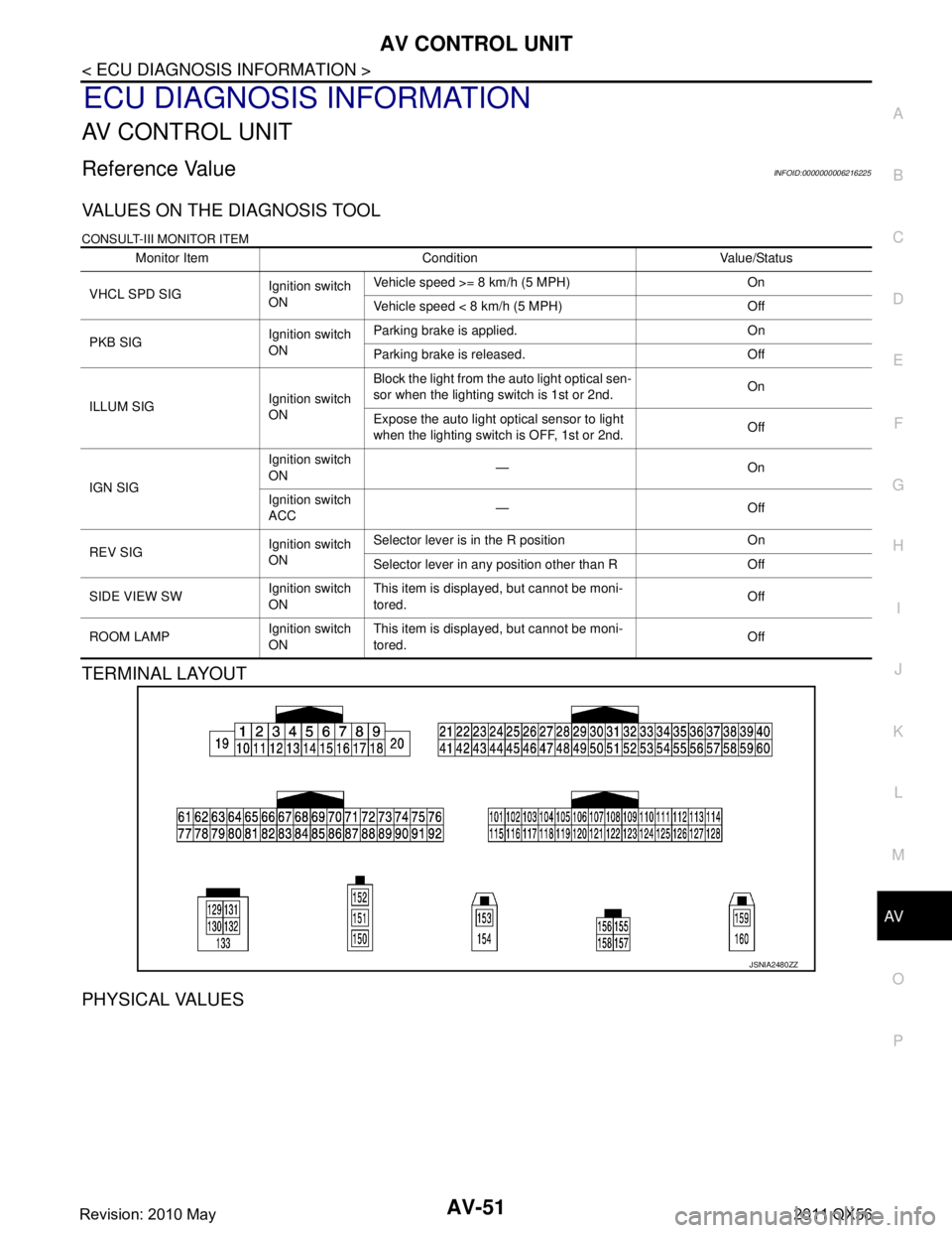
Reference ValueINFOID:0000000006216225
VALUES ON THE DIAGNOSIS TOOL
CONSULT-III MONITOR ITEM
TERMINAL LAYOUT
PHYSICAL VALUES
Monitor Item Condition Value/Status
VHCL SPD SIG Ignition switch
ONVehicle speed >= 8 km/h (5 MPH) On
Vehicle speed < 8 km/h (5 MPH) Off
PKB SIG Ignition switch
ONParking brake is applied. On
Parking brake is released. Off
ILLUM SIG Ignition switch
ONBlock the light from the auto light optical sen-
sor when the lighting switch is 1st or 2nd.
On
Expose the auto light optical sensor to light
when the lighting switch is OFF, 1st or 2nd. Off
IGN SIG Ignition switch
ON
—On
Ignition switch
ACC —Off
REV SIG Ignition switch
ONSelector lever is in the R position On
Selector lever in any position other than R Off
SIDE VIEW SW Ignition switch
ONThis item is displayed, but cannot be moni-
tored.
Off
ROOM LAMP Ignition switch
ONThis item is displayed, but cannot be moni-
tored.
Off
JSNIA2480ZZ
Revision: 2010 May2011 QX56
Page 200 of 5598

AV-52
< ECU DIAGNOSIS INFORMATION >
AV CONTROL UNIT
Te r m i n a l
(Wire color) Description
ConditionReference value
(Approx.)
+ – Signal name Input/
Output
1
(W/B) Ground BOSE amp. ON signal Output Ignition
switch ACC —12.0 V
2
(L) 3
(P) Sound signal front LH Output Ignition
switch ON Sound output
4
(V) 5
(LG) Sound signal rear LH Output Ignition
switch
ON Sound output
6
(Y/G) 15
(B) Steering switch signal A Input Ignition
switch
ON Keep pressing SOURCE
switch.
0 V
Keep pressing MENU UP
switch. 1.0 V
Keep pressing MENU
DOWN switch. 2.0 V
Keep pressing switch 3.0 V
Keep pressing ENTER
switch. 4.0 V
Except for above. 5.0 V
7
(V) Ground ACC power supply Input Ignition
switch ACC — Battery voltage
11
(Y/L) 12
(Y/G) Sound signal front RH Output Ignition
switch
ON Sound output
13
(O) 14
(W) Sound signal rear RH Output Ignition
switch ON Sound output
SKIB3609E
SKIB3609E
SKIB3609E
SKIB3609E
Revision: 2010 May2011 QX56
Page 201 of 5598
AV
AV CONTROL UNITAV-53
< ECU DIAGNOSIS INFORMATION >
C
DE
F
G H
I
J
K L
M B A
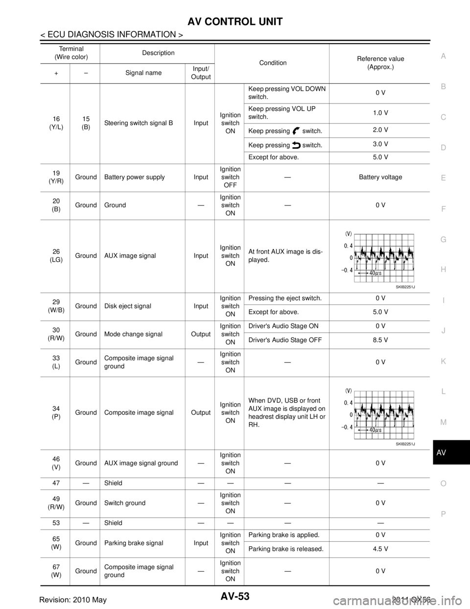
O P16
(Y/L) 15
(B) Steering switch signal B Input Ignition
switch
ON Keep pressing VOL DOWN
switch.
0 V
Keep pressing VOL UP
switch. 1.0 V
Keep pressing switch. 2.0 V
Keep pressing switch. 3.0 V
Except for above. 5.0 V
19
(Y/R) Ground Battery power supply Input Ignition
switch
OFF — Battery voltage
20
(B) Ground Ground — Ignition
switch ON —0 V
26
(LG) Ground AUX image signal Input Ignition
switch ON At front AUX image is dis-
played.
29
(W/B) Ground Disk eject signal Input Ignition
switch
ON Pressing the eject switch. 0 V
Except for above. 5.0 V
30
(R/W) Ground Mode change signal Output Ignition
switch ON Driver's Audio Stage ON 0 V
Driver's Audio Stage OFF 8.5 V
33
(L) Ground
Composite image signal
ground —Ignition
switch ON —0 V
34
(P) Ground Composite image signal Output Ignition
switch ON When DVD, USB or front
AUX image is displayed on
headrest display unit LH or
RH.
46
(V) Ground AUX image signal ground — Ignition
switch ON —0 V
47 — Shield — — — —
49
(R/W) Ground Switch ground — Ignition
switch
ON —0 V
53 — Shield — — — —
65
(W) Ground Parking brake signal Input Ignition
switch ON Parking brake is applied. 0 V
Parking brake is released. 4.5 V
67
(W) Ground Composite image signal
ground —Ignition
switch ON —0 V
Te r m i n a l
(Wire color) Description
ConditionReference value
(Approx.)
+ – Signal name Input/
Output
SKIB2251J
SKIB2251J
Revision: 2010 May2011 QX56
Page 202 of 5598

AV-54
< ECU DIAGNOSIS INFORMATION >
AV CONTROL UNIT
68
(R) Ground Composite image signal Output Ignition
switch ON At DVD image is displayed.
72
(Y/G) Ground Microphone VCC Output Ignition
switch ON —5.0 V
73
(Y/G) Ground Communication signal
(CONT
→DISP) OutputIgnition
switch ON When adjusting display
brightness.
74
(P) —CAN–L Input/
Output —— —
75
(LG) —
AV communication signal
(L) Input/
Output —— —
76
(LG) —AV communication signal
(L) Input/
Output —— —
79
(L/O) Ground Dimmer signal Input Ignition
switch ON Either of the following con-
ditions
Lighting switch is OFF
Lighting switch is 1st or
2nd, and the area around
the vehicle is bright
(shine a light on the opti-
cal sensor) 0 V
Lighting switch is 1st or
2nd, and the area around
the vehicle is dark (block
the light from the optical
sensor) 12.0 V
80
(GR/L) Ground Ignition signal Input Ignition
switch
ON — Battery voltage
81
(R/Y) Ground Reverse signal Input Ignition
switch ON Selector lever is in R posi-
tion.
12.0 V
Selector lever is in other
than R position. 0 V
Te r m i n a l
(Wire color) Description
ConditionReference value
(Approx.)
+ – Signal name Input/
Output
SKIB2251J
PKIB5039J
Revision: 2010 May2011 QX56
Page 203 of 5598
AV
AV CONTROL UNITAV-55
< ECU DIAGNOSIS INFORMATION >
C
DE
F
G H
I
J
K L
M B A
O P
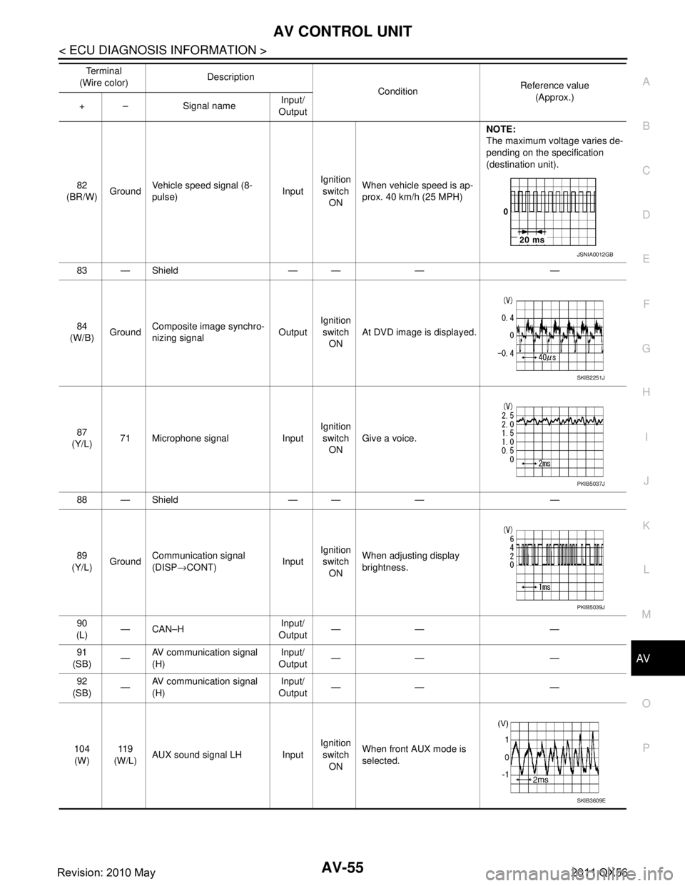
82
(BR/W) GroundVehicle speed signal (8-
pulse) InputIgnition
switch ON When vehicle speed is ap-
prox. 40 km/h (25 MPH) NOTE:
The maximum voltage varies de-
pending on the specification
(destination unit).
83 — Shield — — — —
84
(W/B) Ground Composite image synchro-
nizing signal
OutputIgnition
switch ON At DVD image is displayed.
87
(Y/L) 71 Microphone signal Input Ignition
switch ON Give a voice.
88 — Shield — — — —
89
(Y/L) Ground Communication signal
(DISP
→CONT) InputIgnition
switch ON When adjusting display
brightness.
90
(L) —CAN–H Input/
Output —— —
91
(SB) —AV communication signal
(H) Input/
Output —— —
92
(SB) —
AV communication signal
(H) Input/
Output —— —
104 (W) 11 9
(W/L) AUX sound signal LH Input Ignition
switch ON When front AUX mode is
selected.
Te r m i n a l
(Wire color) Description
ConditionReference value
(Approx.)
+ – Signal name Input/
Output
JSNIA0012GB
SKIB2251J
PKIB5037J
PKIB5039J
SKIB3609E
Revision: 2010 May2011 QX56
Page 204 of 5598
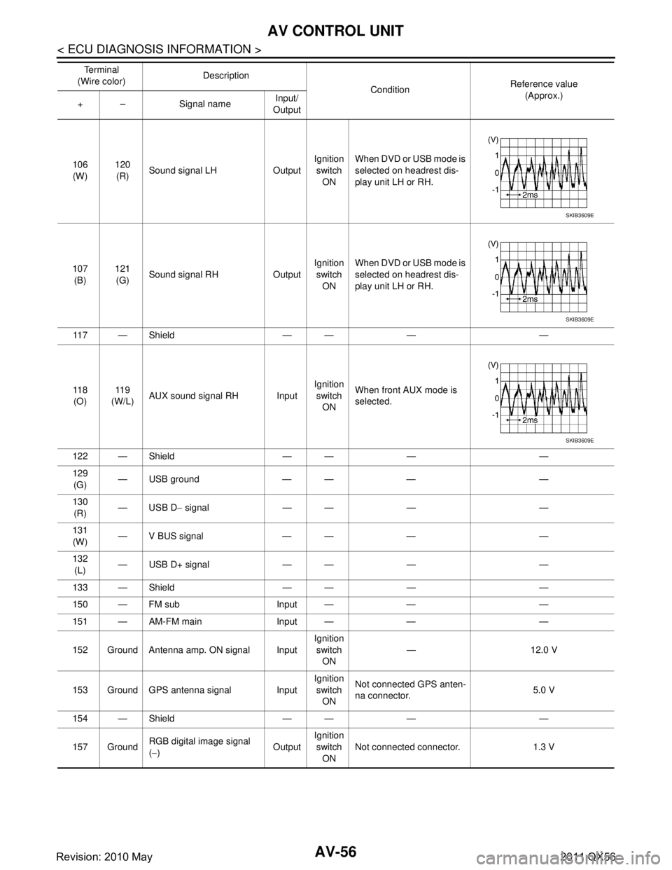
AV-56
< ECU DIAGNOSIS INFORMATION >
AV CONTROL UNIT
106(W) 120
(R) Sound signal LH Output Ignition
switch ON When DVD or USB mode is
selected on headrest dis-
play unit LH or RH.
107 (B) 121
(G) Sound signal RH Output Ignition
switch ON When DVD or USB mode is
selected on headrest dis-
play unit LH or RH.
11 7 — S h i e l d — — — —
11 8 (O) 11 9
(W/L) AUX sound signal RH Input Ignition
switch ON When front AUX mode is
selected.
122 — Shield — — — —
129 (G) — USB ground — — — —
130 (R) — USB D
− signal — — — —
131 (W) — V BUS signal — — — —
132 (L) — USB D+ signal — — — —
133 — Shield — — — —
150 — FM sub Input — — —
151 — AM-FM main Input — — —
152 Ground Antenna amp. ON signal Input Ignition
switch ON —12.0 V
153 Ground GPS antenna signal Input Ignition
switch ON Not connected GPS anten-
na connector.
5.0 V
154 — Shield — — — —
157 Ground RGB digital image signal
(
− ) OutputIgnition
switch
ON Not connected connector. 1.3 V
Te r m i n a l
(Wire color) Description
ConditionReference value
(Approx.)
+ – Signal name Input/
Output
SKIB3609E
SKIB3609E
SKIB3609E
Revision: 2010 May2011 QX56
Page 205 of 5598

AV
AV CONTROL UNITAV-57
< ECU DIAGNOSIS INFORMATION >
C
DE
F
G H
I
J
K L
M B A
O P
Fail-SafeINFOID:0000000006216226
When the ambiance temperature becomes extremely low or extremely high, AV control unit displays the mes-
sage and limits the AV control unit function.
FAIL-SAFE CONDITIONS
When the ambiance temperature is −20 °C ( −4 °F) or lower, or when it is 70 °C (158 °F) or higher
Display
The messages displayed on fail-safe conditions are as shown below:
DESCRIPTION OF CONTROLS
Ability Operation Mode
There is an ability operation mode for Fail-safes due to low or high ambiance temperature.
If HDD data can be read, fail-safe is shown, then normal displays are displayed only for functions which can be
operated.
RELEASE CONDITIONS OF FAIL-SAFE
Fail-safe is released on following conditions and normal mode is restored.
When The Temperature of HDD Is Low or High
If the ambient temperature becomes out of fa il-safe condition range, normal mode is restored.
DTC IndexINFOID:0000000006216227
SELF-DIAGNOSIS RESULTS DISPLAY ITEM
158 GroundRGB digital image signal
(+)
OutputIgnition
switch ON Not connected connector. 1.3 V
159 Ground Satellite radio antenna sig-
nal InputIgnition
switch ON Not connected satellite an-
tenna connector.
5.0 V
Te r m i n a l
(Wire color) Description
ConditionReference value
(Approx.)
+ – Signal name Input/
Output
Fail-safe mode Display (display of the fail-safe condition)
When HDD temperature is low HDD system is experienci
ng problems due to extreme low temperature.
Normal operation will resume when temperature rises.
When HDD temperature is high HDD system is experienci
ng problems due to extreme high temperature.
Normal operation will resume when temperature drops.
Function When Fail-safe Function is activated
Air conditioner Operation Only multifunction switch (preset switch) can be operated.
Display
LED of multifunction switch (preset switch) illuminates.
Aimed temperature, blow angle, and flow rate are displayed in simplified mode.
Audio Operation Only ON/OFF and volume control operations by multifunction switch (preset switch) are possible.
Display No display (“Fail-safe mode” is displayed)
Camera Operation Image tone cannot be controlled.
Display Cannot be superimposed. (warning display, tone control display)
Hands-free phone Operation Cannot be operated.
Navigation Operation Cannot be operated.
Self diagnosis The display in simplified mode of fail-safe condition
CONSULT-III diagnosis Cannot be operated.
Revision: 2010 May2011 QX56
Page 206 of 5598
![INFINITI QX56 2011 Factory Owners Manual
AV-58
< ECU DIAGNOSIS INFORMATION >
AV CONTROL UNIT
DTC Display item Refer to
U1000 CAN COMM CIRCUIT [U1000] AV- 11 8 , "
DiagnosisProcedure"
U1010 CONTROL UNIT (CAN) [1010] AV- 11 9 , "DTC Logic"
INFINITI QX56 2011 Factory Owners Manual
AV-58
< ECU DIAGNOSIS INFORMATION >
AV CONTROL UNIT
DTC Display item Refer to
U1000 CAN COMM CIRCUIT [U1000] AV- 11 8 , "
DiagnosisProcedure"
U1010 CONTROL UNIT (CAN) [1010] AV- 11 9 , "DTC Logic"](/img/42/57033/w960_57033-205.png)
AV-58
< ECU DIAGNOSIS INFORMATION >
AV CONTROL UNIT
DTC Display item Refer to
U1000 CAN COMM CIRCUIT [U1000] AV- 11 8 , "
DiagnosisProcedure"
U1010 CONTROL UNIT (CAN) [1010] AV- 11 9 , "DTC Logic"
U1200 Cont Unit [U1200]AV- 1 2 0 , "DTC Logic"
U1201 GYRO NO CONN [U1201]AV- 1 2 1 , "DTC Logic"
U1202 G-SENSOR NO CONN [U1202]AV- 1 2 2 , "DTC Logic"
U1204 GPS COMM [U1204]AV- 1 2 3 , "Diagnosis Procedure"
U1205 GPS ROM [U1205]AV- 1 2 4 , "Diagnosis Procedure"
U1206 GPS RAM [U1206]AV- 1 2 5 , "Diagnosis Procedure"
U1207 GPS RTC [U1207]AV- 1 2 6 , "Diagnosis Procedure"
U1216 CAN CONT [U1216] AV- 1 2 7 , "DTC Logic"
U1217 BLUETOOTH MODULE [U1217]AV- 1 2 8 , "DTC Logic"
U1218 HDD CONN [U1218]AV- 1 2 9 , "Diagnosis Procedure"
U1219 HDD READ [U1219]AV- 1 3 0 , "Diagnosis Procedure"
U121A HDD WRITE [U121A] AV- 1 3 1 , "Diagnosis Procedure"
U121B HDD COMM [U121B]AV- 1 3 2 , "Diagnosis Procedure"
U121C HDD ACCESS [U121C] AV- 1 3 3 , "Diagnosis Procedure"
U121D DSP CONN [U121D]AV- 1 3 4 , "Diagnosis Procedure"
U121E DSP COMM [U121E]AV- 1 3 5 , "Diagnosis Procedure"
U1225 USB CONTROLLER [U1225] AV- 1 3 6 , "DTC Logic"
U1227 DVD COMM [U1227]AV- 1 3 7 , "Diagnosis Procedure"
U1228 SUB CPU CONN [U1228] AV- 1 3 8 , "DTC Logic"
U1229 iPod CERTIFICATION [U1229]AV- 1 3 9 , "DTC Logic"
U122A CONFIG UNFINISH [U122A]AV- 1 4 0 , "Diagnosis Procedure"
U122E Built-in AUDIO CONN [U122E] AV- 1 4 1 , "DTC Logic"
U1232 ST ANGLE SEN CALIB [1232]AV- 1 4 2 , "Diagnosis Procedure"
U1243 FRONT DISP CONN [U1243]AV- 1 4 3 , "Diagnosis Procedure"
U1244 GPS ANTENNA CONN [U1244]AV- 1 4 5 , "Diagnosis Procedure"
U1258 XM ANTENNA CONN [U1258]AV- 1 4 6 , "Diagnosis Procedure"
U125A 3RD DISP CONN [U125A] AV- 1 4 7 , "Diagnosis Procedure"
U1263 USB OVERCURRENT [U1263]AV- 1 4 8 , "Diagnosis Procedure"
U1264ANTENNA AMP TERMINAL [OPEN or
SHORT] [U1264] AV- 1 4 9 , "Diagnosis Procedure"
U1265
AMP ON TERMINAL [GND-SHORT or VB-
SHORT] [U1265] AV- 1 5 0 , "Diagnosis Procedure"
U1310 CONTROL UNIT (AV) [U1310]
AV- 1 5 2 , "DTC Logic"
Revision: 2010 May2011 QX56