lock INFINITI QX56 2011 Factory Owner's Manual
[x] Cancel search | Manufacturer: INFINITI, Model Year: 2011, Model line: QX56, Model: INFINITI QX56 2011Pages: 5598, PDF Size: 94.53 MB
Page 143 of 5598

ADP-134
< SYMPTOM DIAGNOSIS >
NORMAL OPERATING CONDITION
NORMAL OPERATING CONDITION
DescriptionINFOID:0000000006248440
The following symptoms are normal operations, and they do not indicate a malfunction.
Symptom Cause Action to take Reference page
Entry/exit assist function do not
operate. No initialization has been performed. Perform initialization.
ADP-52, "
SYSTEM INI-
TIALIZATION : Descrip-
tion"
Entry/exit assist function is disabled.
NOTE:
Entry/exit assist function is set to ON be-
fore delivery (initial setting).Change the settings.
ADP-54, "
SYSTEM
SETTING : Description"
Entry assist function does not op-
erate. Manual operation with power seat switch
was performed after exit assist function
execution. Perform the entry as-
sist function. ADP-18, "ENTRY AS-
SIST FUNCTION : Sys-
tem Description"
Lumbar support does not per-
form memory operation. The lumbar support system are con-
trolled independently with no link to the
automatic drive positioner system.
β
SE-16, "LUMBAR SUP-
PORT SYSTEM : Sys-
tem Description"
Memory function, entry/exit as-
sist function, or Intelligent Key in-
terlock function does not
operate. The operating conditions are not fulfilled.
Fulfill the operation
conditions. Memory function :
ADP-15, "
MEMORY
FUNCTION : System
Description"
Entry assist function :
ADP-18, "
ENTRY AS-
SIST FUNCTION : Sys-
tem Description"
Exit assist function :
ADP-17, "
EXIT ASSIST
FUNCTION : System
Description"
Intelligent Key interlock function : ADP-20, "
IN-
TELLIGENT KEY IN-
TERLOCK FUNCTION :
System Description"
Revision: 2010 May2011 QX56
Page 177 of 5598

AV
DIAGNOSIS SYSTEM (AV CONTROL UNIT)AV-29
< SYSTEM DESCRIPTION >
C
DE
F
G H
I
J
K L
M B A
O P
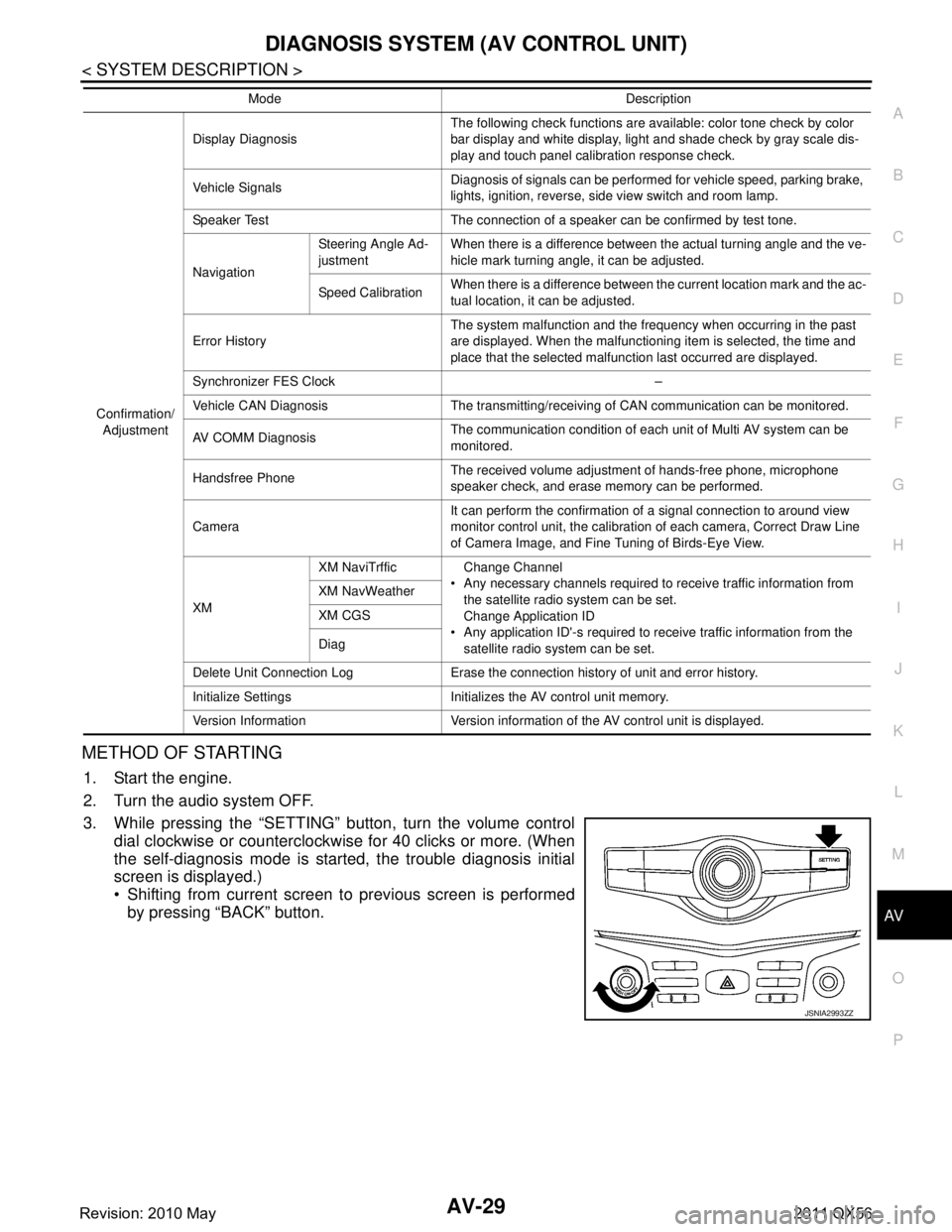
METHOD OF STARTING
1. Start the engine.
2. Turn the audio system OFF.
3. While pressing the βSETTINGβ button, turn the volume control dial clockwise or counterclockwise for 40 clicks or more. (When
the self-diagnosis mode is start ed, the trouble diagnosis initial
screen is displayed.)
Shifting from current screen to previous screen is performed
by pressing βBACKβ button.
Confirmation/
Adjustment Display Diagnosis
The following check functions are available: color tone check by color
bar display and white display, light and shade check by gray scale dis-
play and touch panel calibration response check.
Vehicle Signals Diagnosis of signals can be performed for vehicle speed, parking brake,
lights, ignition, reverse, side view switch and room lamp.
Speaker Test The connection of a speaker can be confirmed by test tone.
Navigation Steering Angle Ad-
justment
When there is a difference between the actual turning angle and the ve-
hicle mark turning angle, it can be adjusted.
Speed Calibration When there is a difference between the current location mark and the ac-
tual location, it can be adjusted.
Error History The system malfunction and the frequency when occurring in the past
are displayed. When the malfunctioning item is selected, the time and
place that the selected malfunction last occurred are displayed.
Synchronizer FES Clock β
Vehicle CAN Diagnosis The transmitting/receiving of CAN communication can be monitored.
AV COMM Diagnosis The communication condition of each unit of Multi AV system can be
monitored.
Handsfree Phone The received volume adjustment of hands-free phone, microphone
speaker check, and erase memory can be performed.
Camera It can perform the confirmation of a signal connection to around view
monitor control unit, the calibration
of each camera, Correct Draw Line
of Camera Image, and Fine Tuning of Birds-Eye View.
XM XM NaviTrffic Change Channel
Any necessary channels required to receive traffic information from the satellite radio system can be set.
Change Application ID
Any application ID'-s required to receive traffic information from the satellite radio system can be set.
XM NavWeather
XM CGS
Diag
Delete Unit Connection Log Erase the connection history of unit and error history.
Initialize Settings Initializes the AV control unit memory.
Version Information Version information of the AV control unit is displayed. Mode Description
JSNIA2993ZZ
Revision: 2010 May2011 QX56
Page 181 of 5598

AV
DIAGNOSIS SYSTEM (AV CONTROL UNIT)AV-33
< SYSTEM DESCRIPTION >
C
DE
F
G H
I
J
K L
M B A
O P
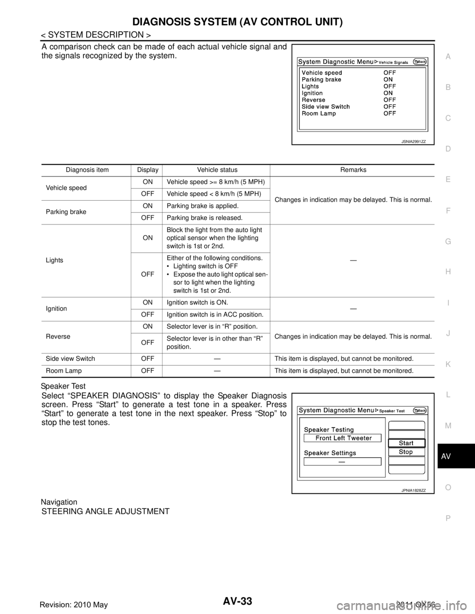
A comparison check can be made of each actual vehicle signal and
the signals recognized by the system.
Sp ea ke r Tes t
Select βSPEAKER DIAGNOSISβ to display the Speaker Diagnosis
screen. Press βStartβ to generate a test tone in a speaker. Press
βStartβ to generate a test tone in the next speaker. Press βStopβ to
stop the test tones.
Navigation
STEERING ANGLE ADJUSTMENT
JSNIA2991ZZ
Diagnosis item Display Vehicle status Remarks
Vehicle speed ON Vehicle speed >= 8 km/h (5 MPH)
Changes in indication may be delayed. This is normal.
OFF Vehicle speed < 8 km/h (5 MPH)
Parking brake ON Parking brake is applied.
OFF Parking brake is released.
Lights ON
Block the light from the auto light
optical sensor when the lighting
switch is 1st or 2nd.
β
OFF Either of the following conditions.
Lighting switch is OFF
Expose the auto light optical sen-
sor to light when the lighting
switch is 1st or 2nd.
Ignition ON Ignition switch is ON.
β
OFF Ignition switch is in ACC position.
Reverse ON Selector lever is in βRβ position.
Changes in indication may be delayed. This is normal.
OFF Selector lever is in other than βRβ
position.
Side view Switch OFF β This item is displayed, but cannot be monitored.
Room Lamp OFF β This item is displayed, but cannot be monitored.
JPNIA1828ZZ
Revision: 2010 May2011 QX56
Page 190 of 5598

AV-42
< SYSTEM DESCRIPTION >
DIAGNOSIS SYSTEM (AV CONTROL UNIT)
DATA MONITOR
ALL SIGNALS
Displays the status of the following vehicle signals inputted into the AV control unit.
For each signal, actual signal can be compared with the condition recognized on the system.
AV COMM CIRCUIT [U1300]
SWITCH CONN [U1240]When either one of the following items are
detected:
multifunction switch power supply and
ground circuits are malfunctioning.
AV communication circuits between AV
control unit and multifunction switch are
malfunctioning. Multifunction switch power supply and
ground circuits.
AV communication circuits between AV control unit and multifunction switch.
AV COMM CIRCUIT [U1300]
AROUND CAMERA CONN [U125B] When either one of the following items are
detected:
around view monitor control unit power
supply and ground circuits are malfunc-
tioning.
AV communication circuits between AV control unit and around view monitor
control unit are malfunctioning. Around view monitor control unit power
supply and ground circuits.
AV communication circuits between AV control unit and around view monitor
control unit.
AV COMM CIRCUIT [U1300]
SONAR CONN [U125C] When either one of the following items are
detected:
sonar control unit power supply and
ground circuits are malfunctioning.
AV communication circuits between AV control unit and sonar control unit are
malfunctioning. Sonar control unit power supply and
ground circuits.
AV communication circuits between AV control unit and sonar control unit.
AV COMM CIRCUIT [U1300]
SWITCH CONN [U1240]
SONAR CONN [U125C]
AROUND CAMERA CONN [U125B] AV communication circuits between AV
control unit and multifunction switch are
malfunctioning.AV communication circuits between AV
control unit and multifunction switch.
AV COMM CIRCUIT [U1300]
SWITCH CONN [U1240]
SONAR CONN [U125C]
AROUND CAMERA CONN [U125B]
VIDEO DIST CONN [U1246] Error item Description Possible malfunction factor/Action to take
Display Item Display Vehicle status Remarks
VHCL SPD SIG On Vehicle speed >= 8 km/h (5 MPH)
Changes in indication may be delayed. This is
normal.
Off Vehicle speed < 8 km/h (5 MPH)
PKB SIG On Parking brake is applied.
Off Parking brake is released.
ILLUM SIG On
Block the light from the auto light op-
tical sensor when the lighting switch
is 1st or 2nd.
β
Off Either of the following conditions.
Lighting switch is OFF
Expose the auto light optical sen-
sor to light when the lighting switch
is 1st or 2nd.
IGN SIG On Ignition switch is ON
Off Ignition switch is in ACC position
REV SIG On Selector lever is in R position
Changes in indication may be delayed. This is
normal.
Off Selector lever is in any position other
than R
Revision: 2010 May2011 QX56
Page 199 of 5598

AV
AV CONTROL UNITAV-51
< ECU DIAGNOSIS INFORMATION >
C
DE
F
G H
I
J
K L
M B A
O P
ECU DIAGNOSIS INFORMATION
AV CONTROL UNIT
Reference ValueINFOID:0000000006216225
VALUES ON THE DIAGNOSIS TOOL
CONSULT-III MONITOR ITEM
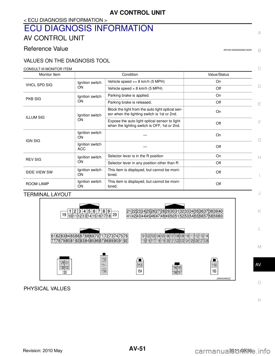
TERMINAL LAYOUT
PHYSICAL VALUES
Monitor Item Condition Value/Status
VHCL SPD SIG Ignition switch
ONVehicle speed >= 8 km/h (5 MPH) On
Vehicle speed < 8 km/h (5 MPH) Off
PKB SIG Ignition switch
ONParking brake is applied. On
Parking brake is released. Off
ILLUM SIG Ignition switch
ONBlock the light from the auto light optical sen-
sor when the lighting switch is 1st or 2nd.
On
Expose the auto light optical sensor to light
when the lighting switch is OFF, 1st or 2nd. Off
IGN SIG Ignition switch
ON
βOn
Ignition switch
ACC βOff
REV SIG Ignition switch
ONSelector lever is in the R position On
Selector lever in any position other than R Off
SIDE VIEW SW Ignition switch
ONThis item is displayed, but cannot be moni-
tored.
Off
ROOM LAMP Ignition switch
ONThis item is displayed, but cannot be moni-
tored.
Off
JSNIA2480ZZ
Revision: 2010 May2011 QX56
Page 202 of 5598

AV-54
< ECU DIAGNOSIS INFORMATION >
AV CONTROL UNIT
68
(R) Ground Composite image signal Output Ignition
switch ON At DVD image is displayed.
72
(Y/G) Ground Microphone VCC Output Ignition
switch ON β5.0 V
73
(Y/G) Ground Communication signal
(CONT
βDISP) OutputIgnition
switch ON When adjusting display
brightness.
74
(P) βCANβL Input/
Output ββ β
75
(LG) β
AV communication signal
(L) Input/
Output ββ β
76
(LG) βAV communication signal
(L) Input/
Output ββ β
79
(L/O) Ground Dimmer signal Input Ignition
switch ON Either of the following con-
ditions
Lighting switch is OFF
Lighting switch is 1st or
2nd, and the area around
the vehicle is bright
(shine a light on the opti-
cal sensor) 0 V
Lighting switch is 1st or
2nd, and the area around
the vehicle is dark (block
the light from the optical
sensor) 12.0 V
80
(GR/L) Ground Ignition signal Input Ignition
switch
ON β Battery voltage
81
(R/Y) Ground Reverse signal Input Ignition
switch ON Selector lever is in R posi-
tion.
12.0 V
Selector lever is in other
than R position. 0 V
Te r m i n a l
(Wire color) Description
ConditionReference value
(Approx.)
+ β Signal name Input/
Output
SKIB2251J
PKIB5039J
Revision: 2010 May2011 QX56
Page 389 of 5598

BCS
BCS-1
ELECTRICAL & POWER CONTROL
C
DE
F
G H
I
J
K L
B
SECTION BCS
A
O P
N
CONTENTS
BODY CONTROL SYSTEM
PRECAUTION ................
...............................3
PRECAUTIONS .............................................. .....3
Precaution for Supplemental Restraint System
(SRS) "AIR BAG" and "SEAT BELT PRE-TEN-
SIONER" ............................................................. ......
3
SYSTEM DESCRIPTION ..............................4
COMPONENT PARTS ................................... .....4
BODY CONTROL SYSTEM ........................................4
BODY CONTROL SYSTEM : Component Parts
Location ............................................................... ......
4
POWER CONSUMPTION CONTROL SYSTEM ... ......4
POWER CONSUMPTION CONTROL SYSTEM :
Component Parts Location ........................................
4
SYSTEM ..............................................................6
BODY CONTROL SYSTEM ........................................6
BODY CONTROL SYSTEM : System Description ......6
COMBINATION SWITCH READING SYSTEM ..... ......7
COMBINATION SWITCH READING SYSTEM :
System Diagram ........................................................
7
COMBINATION SWITCH READING SYSTEM :
System Description ...................................................
7
SIGNAL BUFFER SYSTEM ........................ ..............10
SIGNAL BUFFER SYSTEM : System Diagram .. ....10
SIGNAL BUFFER SYSTEM : System Description ....10
POWER CONSUMPTION CONTROL SYSTEM ... ....11
POWER CONSUMPTION CONTROL SYSTEM :
System Diagram ......................................................
11
POWER CONSUMPTION CONTROL SYSTEM :
System Description .................................................
11
DIAGNOSIS SYSTEM (BCM) ............................14
COMMON ITEM ..................................................... ....14
COMMON ITEM : CONSULT-III Function (BCM -
COMMON ITEM) .....................................................
14
DOOR LOCK .......................................................... ....15
DOOR LOCK : CONSULT-III Function (BCM -
DOOR LOCK) ..........................................................
15
REAR WINDOW DEFOGGER ............................... ....16
REAR WINDOW DEFOGGER : CONSULT-III
Function (BCM - REAR DEFOGGER) .....................
17
BUZZER ................................................................. ....17
BUZZER : CONSULT-III Function (BCM - BUZZ-
ER) ..........................................................................
17
INT LAMP ............................................................... ....17
INT LAMP : CONSULT-III Function (BCM - INT
LAMP) ......................................................................
18
HEADLAMP ........................................................... ....19
HEADLAMP : CONSULT-III Function (BCM -
HEAD LAMP) ...........................................................
19
WIPER .................................................................... ....21
WIPER : CONSULT-III Function (BCM - WIPER) ....21
FLASHER ............................................................... ....23
FLASHER : CONSULT-III Function (BCM -
FLASHER) ...............................................................
23
INTELLIGENT KEY ................................................ ....24
INTELLIGENT KEY : CONSULT-III Function
(BCM - INTELLIGENT KEY) ....................................
24
COMB SW .............................................................. ....27
COMB SW : CONSULT-III Function (BCM -
COMB SW) ..............................................................
27
BCM ....................................................................... ....28
BCM : CONSULT-III Function (BCM - BCM) ...........28
IMMU ...................................................................... ....28
IMMU : CONSULT-III Function (BCM - IMMU) ........28
Revision: 2010 May2011 QX56
Page 394 of 5598

BCS-6
< SYSTEM DESCRIPTION >
SYSTEM
SYSTEM
BODY CONTROL SYSTEM
BODY CONTROL SYSTEM : System DescriptionINFOID:0000000006274789
OUTLINE
BCM (Body Control Module) controls the various electrical components. It inputs the information required to
the control from CAN communication and the signal received from each switch and sensor.
BCM has combination switch reading function for reading the operation status of combination switches (light,
turn signal, wiper and washer) in addition to a function fo r controlling the operation of various electrical com-
ponents. It also has the signal transmission function as the passed point of signal and the power saving con-
trol function that reduces the power c onsumption with the ignition switch OFF.
BCM is equipped with the diagnosis function that perfo rms the diagnosis with CONSULT-III and various set-
tings.
BCM CONTROL FUNCTION LIST
System Reference
Combination switch reading system BCS-7, "
COMBINATION SWITCH READING SYSTEM : System
Diagram"
Signal buffer system
BCS-10, "SIGNAL BUFFER SYSTEM : System Diagram"
Power consumption control systemBCS-11, "POWER CONSUMPTION CONTROL SYSTEM : Sys-
tem Diagram"
Auto light system
EXL-11, "AUTO LIGHT SYSTEM : System Diagram"
Turn signal and hazard warning lamp systemEXL-18, "TURN SIGNAL AND HAZARD WARNING LAMP SYS-
TEM : System Diagram"
Headlamp system
EXL-10, "HEADLAMP SYSTEM : System Diagram"
Daytime running light systemEXL-14, "DAYTIME RUNNING LIGHT SYSTEM : System Dia-
gram"
Parking, license plate, side maker and tail lamps system
EXL-18, "PARKING, LICENSE PLATE, SIDE MARKER AND
TAIL LAMP SYSTEM : System Diagram"
Front fog lamp system
EXL-20, "FRONT FOG LAMP SYSTEM : System Diagram"
Exterior lamp battery saver systemEXL-20, "EXTERIOR LAMP BATTERY SAVER SYSTEM : Sys-
tem Diagram"
Interior room la
mp control system INL-6, "INTERIOR ROOM LAMP CONTROL SYSTEM : System
Diagram"
Interior room lamp battery saver system
INL-9, "INTERIOR ROOM LAMP BATTERY SAVER SYSTEM :
System Diagram"
Front wiper and washer systemWW-7, "FRONT WIPER AND WASHER SYSTEM : System Dia-
gram"
Rear wiper and washer systemWW-10, "REAR WIPER AND WASHER SYSTEM : System Dia-
gram"
Headlamp washer system
WW-13, "HEADLAMP WASHER SYSTEM : System Diagram"
Warning chime systemWCS-6, "WARNING CHIME SYSTEM : System Diagram"
Power door lock systemDLK-16, "System Diagram"
Infiniti Vehicle immobilizer System (IVIS)SEC-15, "INFINITI VEHICLE IMMOBILIZER SYSTEM-NATS :
System Diagram"
Vehicle security systemTheft warning alarm
SEC-17, "VEHICLE SECURITY SYSTEM : System Diagram"Panic alarm
Rear window defogger system DEF-6, "
System Diagram"
Intelligent Key system/engine start systemDLK-18, "INTELLIGENT KEY SYSTEM : System Diagram"
Power window system PWC-8, "SystemDiagram"
Retained accessory power (RAP) systemPWC-8, "System Description"
Revision: 2010 May2011 QX56
Page 400 of 5598

BCS-12
< SYSTEM DESCRIPTION >
SYSTEM
Low power consumption mode (BCM sleep)- Low power consumption control is active
- CAN transmission is stopped
LOW POWER CONSUMPTION CONTROL WITH BCM
BCM reduces the power consumption with the following operation in the low power consumption mode.
The reading interval of the each switches changes from 10 ms interval to 60 ms interval.
Sleep mode activation
BCM receives the sleep-ready signal (ready) from IPDM E/R, combination meter and automatic back door
control module via CAN communication.
BCM transmits the sleep wake up signal (sleep) to each unit when all of the CAN sleep conditions are ful- filled.
Each unit stops the transmission of CAN communication with the sleep wake up signal. BCM is in CAN com- munication sleep mode.
BCM is in the low power consumption mode and perform the low power consumption control when all of the
BCM sleep conditions are fulfilled with CAN sleep condition.
Sleep condition
Wake-up operation
BCM transmits sleep wake up signal (wake up) to eac h unit when any condition listed below is established,
and then goes into normal mode from low power consumption mode.
Each unit starts transmissions with CAN communication by receiving sleep wake up signals. Each unit trans- mit wake up signals to BCM with CAN communication to convey the start of CAN communication.
CAN sleep condition BCM sleep condition
Receiving the sleep-ready signal (ready) from all units
Ignition switch: OFF
Vehicle security system: Not operation
Warning chime: Not operation
Intelligent Key system buzzer: Not operation
Stop lamp switch: OFF
Turn signal indicator lamp: Not operation
Exterior lamp: OFF
Door lock status: No change
CONSULT-III communication status: Not communication
Meter display signal: Non-transmission
Door switch status: No change
Rear window defogger: OFF
Driver door lock status: No change Interior room lamp battery saver: Time out
RAP system: OFF
IVIS: Not operation
Remote keyless entry receiver communication status: No com-
munication
LOCK indicator lamp: Not operation
ACC indicator lamp: Not operation
ON indicator lamp: Not operation
Revision: 2010 May2011 QX56
Page 401 of 5598

BCS
SYSTEMBCS-13
< SYSTEM DESCRIPTION >
C
DE
F
G H
I
J
K L
B A
O P
N
Wake-up condition
Wake-up condition
Receiving the sleep-ready signal (Not-ready) from any units
Push-button ignition switch (push switch): OFF β ON
Hazard switch: ON
HI BEAM switch: OFF β ON, ON β OFF
PASSING switch: OFF β ON, ON β OFF
HEADLAMP 1 switch: OFF β ON, ON β OFF
HEADLAMP 2 switch: OFF β ON, ON β OFF
TAIL LAMP switch: OFF β ON
FR FOG switch: OFF β ON, ON β OFF
TURN RH: OFF β ON, ON β OFF
TURN LH: OFF β ON, ON β OFF
Driver door switch: OFF β ON, ON β OFF
Passenger door switch: OFF β ON, ON β OFF
Rear RH door switch: OFF β ON, ON β OFF
Rear LH door switch: OFF β ON, ON β OFF
Back door switch: OFF β ON, ON β OFF
Driver door request switch: OFF β ON
Passenger door request switch: OFF β ON
Back door request switch: OFF β ON
Back door opener switch: OFF β ON
Stop lamp switch: ON
Door lock and unlock switch:
NEUTRAL β LOCK, NEUTRAL β UNLOCK
Front door lock assembly (drive r side) (door key cylinder switch):
NEUTRAL β LOCK, NEUTRAL β UNLOCK
Remote keyless entry receiver communication: Receiving
Front door lock assembly (driver side) (unlock sensor):
OFF β
ON, ON β OFF
Revision: 2010 May2011 QX56