service INFINITI QX56 2011 Factory Service Manual
[x] Cancel search | Manufacturer: INFINITI, Model Year: 2011, Model line: QX56, Model: INFINITI QX56 2011Pages: 5598, PDF Size: 94.53 MB
Page 4237 of 5598
SUNROOF DOES NOT OPERATE PROPERLYRF-23
< SYMPTOM DIAGNOSIS >
C
DE
F
G H
I
J
L
M A
B
RF
N
O P
SYMPTOM DIAGNOSIS
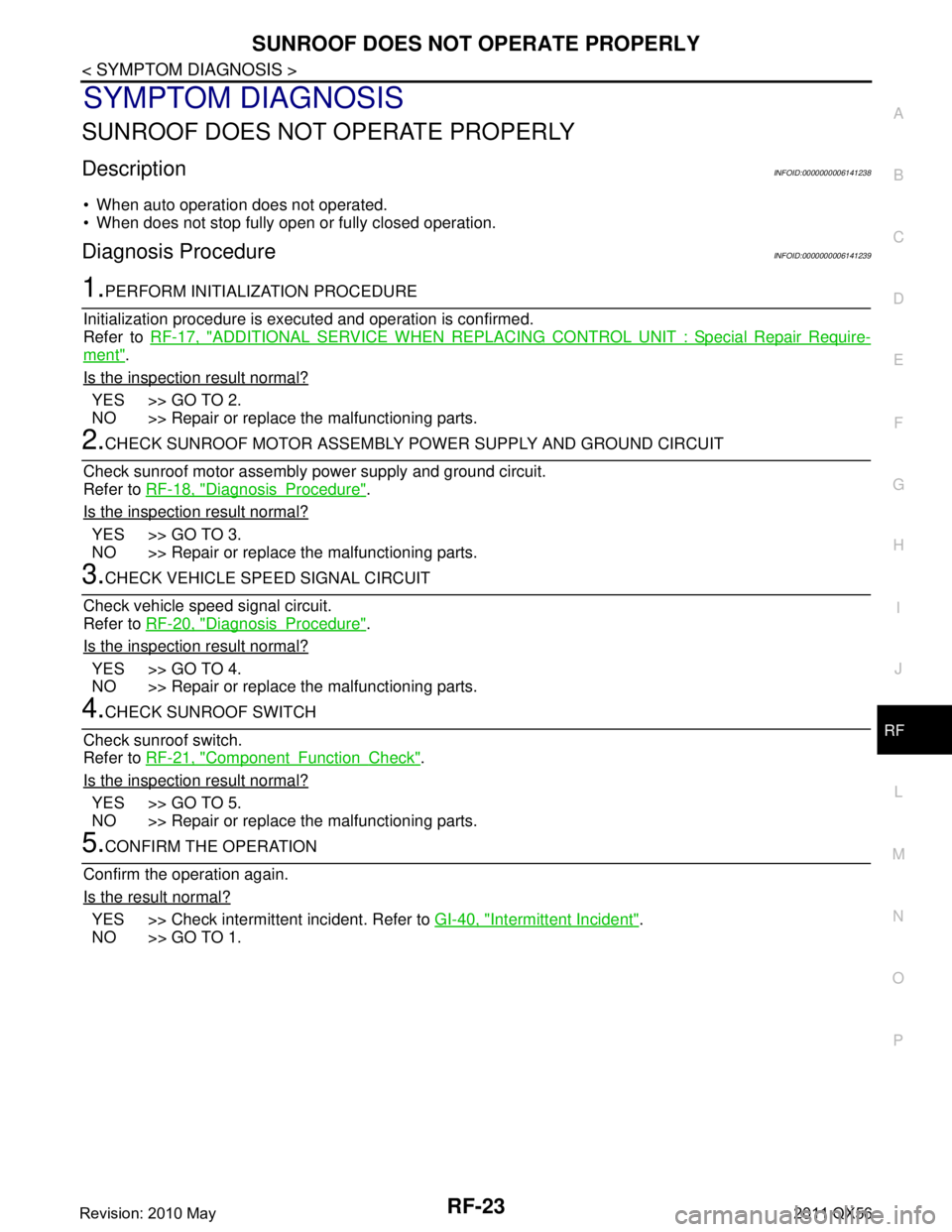
SUNROOF DOES NOT OPERATE PROPERLY
DescriptionINFOID:0000000006141238
When auto operation does not operated.
When does not stop fully open or fully closed operation.
Diagnosis ProcedureINFOID:0000000006141239
1.PERFORM INITIALIZATION PROCEDURE
Initialization procedure is executed and operation is confirmed.
Refer to RF-17, "
ADDITIONAL SERVICE WHEN REPLACING CO NTROL UNIT : Special Repair Require-
ment".
Is the inspection result normal?
YES >> GO TO 2.
NO >> Repair or replace the malfunctioning parts.
2.CHECK SUNROOF MOTOR ASSEMBLY POWER SUPPLY AND GROUND CIRCUIT
Check sunroof motor assembly power supply and ground circuit.
Refer to RF-18, "
DiagnosisProcedure".
Is the inspection result normal?
YES >> GO TO 3.
NO >> Repair or replace the malfunctioning parts.
3.CHECK VEHICLE SPEED SIGNAL CIRCUIT
Check vehicle speed signal circuit.
Refer to RF-20, "
DiagnosisProcedure".
Is the inspection result normal?
YES >> GO TO 4.
NO >> Repair or replace the malfunctioning parts.
4.CHECK SUNROOF SWITCH
Check sunroof switch.
Refer to RF-21, "
ComponentFunctionCheck".
Is the inspection result normal?
YES >> GO TO 5.
NO >> Repair or replace the malfunctioning parts.
5.CONFIRM THE OPERATION
Confirm the operation again.
Is the result normal?
YES >> Check intermittent incident. Refer to GI-40, "Intermittent Incident".
NO >> GO TO 1.
Revision: 2010 May2011 QX56
Page 4238 of 5598
RF-24
< SYMPTOM DIAGNOSIS >
SUNROOF DOES NOT OPERATE ANTI-PINCH FUNCTION
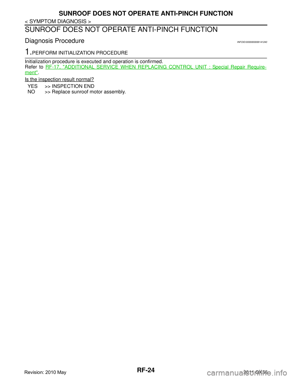
SUNROOF DOES NOT OPERATE ANTI-PINCH FUNCTION
Diagnosis ProcedureINFOID:0000000006141240
1.PERFORM INITIALIZATION PROCEDURE
Initialization procedure is exec uted and operation is confirmed.
Refer to RF-17, "
ADDITIONAL SERVICE WHEN REPLACING CO NTROL UNIT : Special Repair Require-
ment".
Is the inspection result normal?
YES >> INSPECTION END
NO >> Replace sunroof motor assembly.
Revision: 2010 May2011 QX56
Page 4240 of 5598
RF-26
< SYMPTOM DIAGNOSIS >
SQUEAK AND RATTLE TROUBLE DIAGNOSES
SQUEAK AND RATTLE TROUBLE DIAGNOSES
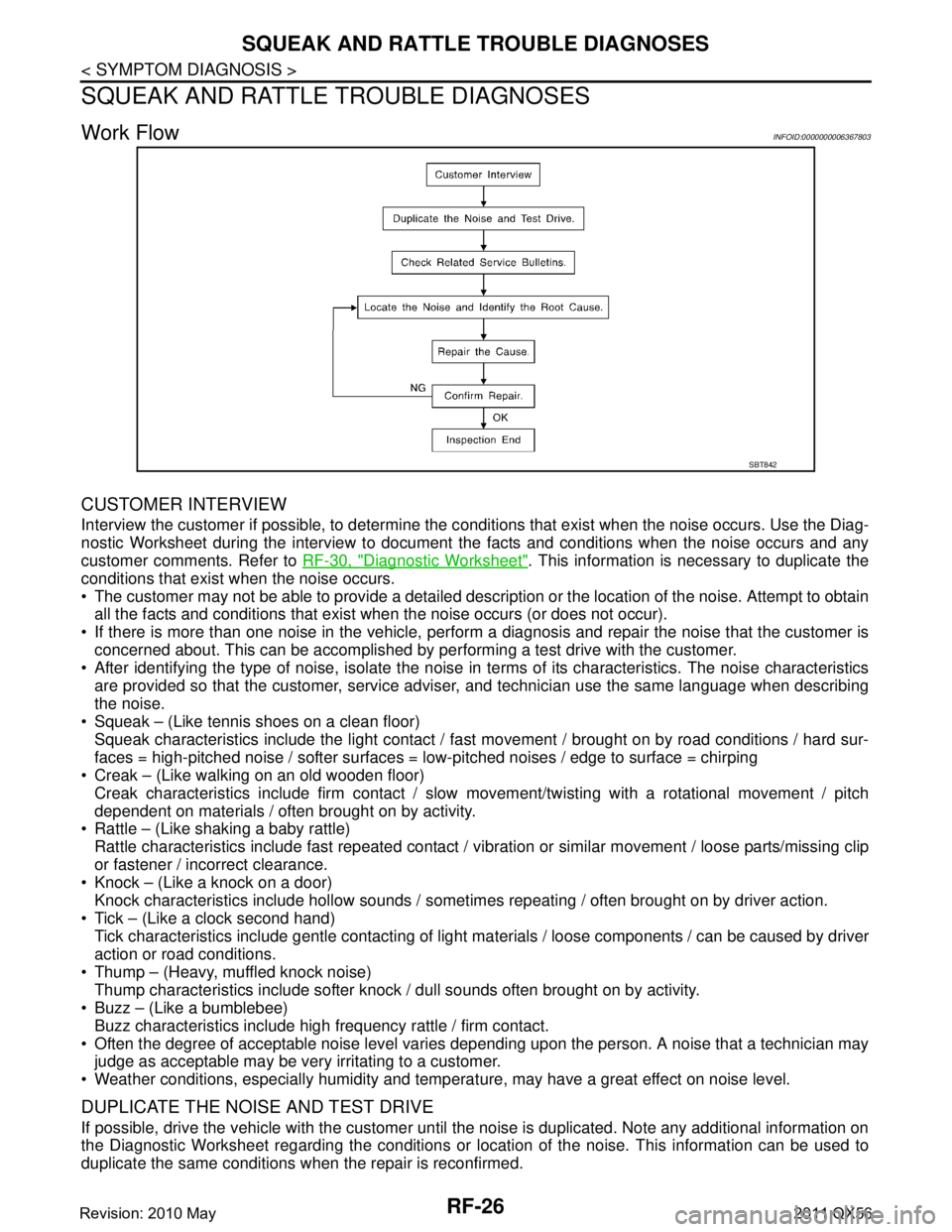
Work FlowINFOID:0000000006367803
CUSTOMER INTERVIEW
Interview the customer if possible, to determine the c onditions that exist when the noise occurs. Use the Diag-
nostic Worksheet during the interview to document the facts and conditions when the noise occurs and any
customer comments. Refer to RF-30, "
Diagnostic Worksheet". This information is necessary to duplicate the
conditions that exist when the noise occurs.
The customer may not be able to provide a detailed description or the location of the noise. Attempt to obtain all the facts and conditions that exist w hen the noise occurs (or does not occur).
If there is more than one noise in the vehicle, perform a diagnosis and repair the noise that the customer is
concerned about. This can be accomplished by per forming a test drive with the customer.
After identifying the type of noise, isolate the noise in terms of its characteristics. The noise characteristics
are provided so that the customer, service advis er, and technician use the same language when describing
the noise.
Squeak – (Like tennis shoes on a clean floor)
Squeak characteristics include the light contact / fast movement / brought on by road conditions / hard sur-
faces = high-pitched noise / softer surfaces = low-pitched noises / edge to surface = chirping
Creak – (Like walking on an old wooden floor)
Creak characteristics include firm contact / slow movement/twisting with a rotational movement / pitch
dependent on materials / often brought on by activity.
Rattle – (Like shaking a baby rattle)
Rattle characteristics include fast repeated contact / vibr ation or similar movement / loose parts/missing clip
or fastener / incorrect clearance.
Knock – (Like a knock on a door)
Knock characteristics include hollow sounds / someti mes repeating / often brought on by driver action.
Tick – (Like a clock second hand) Tick characteristics include gentle contacting of light materials / loose components / can be caused by driver
action or road conditions.
Thump – (Heavy, muffled knock noise) Thump characteristics include softer knock / dull sounds often brought on by activity.
Buzz – (Like a bumblebee)
Buzz characteristics include high frequency rattle / firm contact.
Often the degree of acceptable noise level varies depending upon the person. A noise that a technician may
judge as acceptable may be very irritating to a customer.
Weather conditions, especially humidity and temperat ure, may have a great effect on noise level.
DUPLICATE THE NOISE AND TEST DRIVE
If possible, drive the vehicle with the customer until the noise is duplicated. Note any additional information on
the Diagnostic Worksheet regarding the conditions or lo cation of the noise. This information can be used to
duplicate the same conditions when the repair is reconfirmed.
SBT842
Revision: 2010 May2011 QX56
Page 4241 of 5598
SQUEAK AND RATTLE TROUBLE DIAGNOSESRF-27
< SYMPTOM DIAGNOSIS >
C
DE
F
G H
I
J
L
M A
B
RF
N
O P
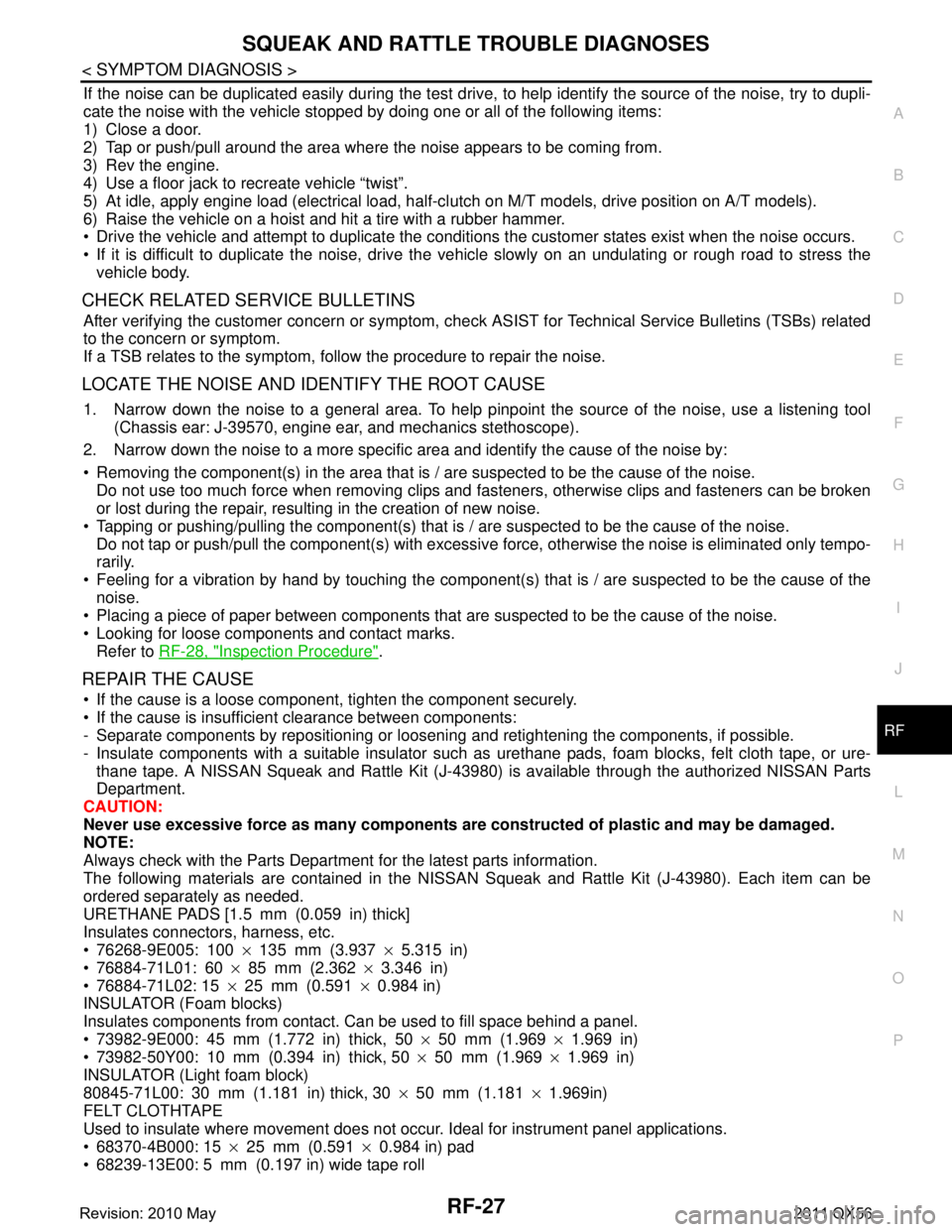
If the noise can be duplicated easily during the test drive, to help identify the source of the noise, try to dupli-
cate the noise with the vehicle stopped by doing one or all of the following items:
1) Close a door.
2) Tap or push/pull around the area where the noise appears to be coming from.
3) Rev the engine.
4) Use a floor jack to recreate vehicle “twist”.
5) At idle, apply engine load (electrical load, half-cl utch on M/T models, drive position on A/T models).
6) Raise the vehicle on a hoist and hit a tire with a rubber hammer.
Drive the vehicle and attempt to duplicate the conditions the customer states exist when the noise occurs.
If it is difficult to duplicate the noise, drive the vehicle slowly on an undulating or rough road to stress the vehicle body.
CHECK RELATED SERVICE BULLETINS
After verifying the customer concern or symptom, che ck ASIST for Technical Service Bulletins (TSBs) related
to the concern or symptom.
If a TSB relates to the symptom, follow the procedure to repair the noise.
LOCATE THE NOISE AND IDENTIFY THE ROOT CAUSE
1. Narrow down the noise to a general area. To help pinpoint the source of the noise, use a listening tool
(Chassis ear: J-39570, engine ear, and mechanics stethoscope).
2. Narrow down the noise to a more specific area and identify the cause of the noise by:
Removing the component(s) in the area that is / are suspected to be the cause of the noise.
Do not use too much force when removing clips and fasteners, otherwise clips and fasteners can be broken
or lost during the repair, resulting in the creation of new noise.
Tapping or pushing/pulling the component(s) that is / are suspected to be the cause of the noise.
Do not tap or push/pull the component(s) with excessive force, otherwise the noise is eliminated only tempo-
rarily.
Feeling for a vibration by hand by touching the component(s ) that is / are suspected to be the cause of the
noise.
Placing a piece of paper between components that are suspected to be the cause of the noise.
Looking for loose components and contact marks. Refer to RF-28, "
Inspection Procedure".
REPAIR THE CAUSE
If the cause is a loose component, tighten the component securely.
If the cause is insufficient clearance between components:
- Separate components by repositioning or loosening and retightening the components, if possible.
- Insulate components with a suitable insulator such as urethane pads, foam blocks, felt cloth tape, or ure-
thane tape. A NISSAN Squeak and Rattle Kit (J-43980) is available through the authorized NISSAN Parts
Department.
CAUTION:
Never use excessive force as many components are constructed of plastic and may be damaged.
NOTE:
Always check with the Parts Department for the latest parts information.
The following materials are contained in the NISSA N Squeak and Rattle Kit (J-43980). Each item can be
ordered separately as needed.
URETHANE PADS [1.5 mm (0.059 in) thick]
Insulates connectors, harness, etc.
76268-9E005: 100 ×135 mm (3.937 ×5.315 in)
76884-71L01: 60 ×85 mm (2.362 ×3.346 in)
76884-71L02: 15 ×25 mm (0.591 ×0.984 in)
INSULATOR (Foam blocks)
Insulates components from contact. Can be used to fill space behind a panel.
73982-9E000: 45 mm (1.772 in) thick, 50 ×50 mm (1.969 ×1.969 in)
73982-50Y00: 10 mm (0.394 in) thick, 50 ×50 mm (1.969 ×1.969 in)
INSULATOR (Light foam block)
80845-71L00: 30 mm (1.181 in) thick, 30 ×50 mm (1.181 ×1.969in)
FELT CLOTHTAPE
Used to insulate where movement does not occur. Ideal for instrument panel applications.
68370-4B000: 15 ×25 mm (0.591 ×0.984 in) pad
68239-13E00: 5 mm (0.197 in) wide tape roll
Revision: 2010 May2011 QX56
Page 4248 of 5598
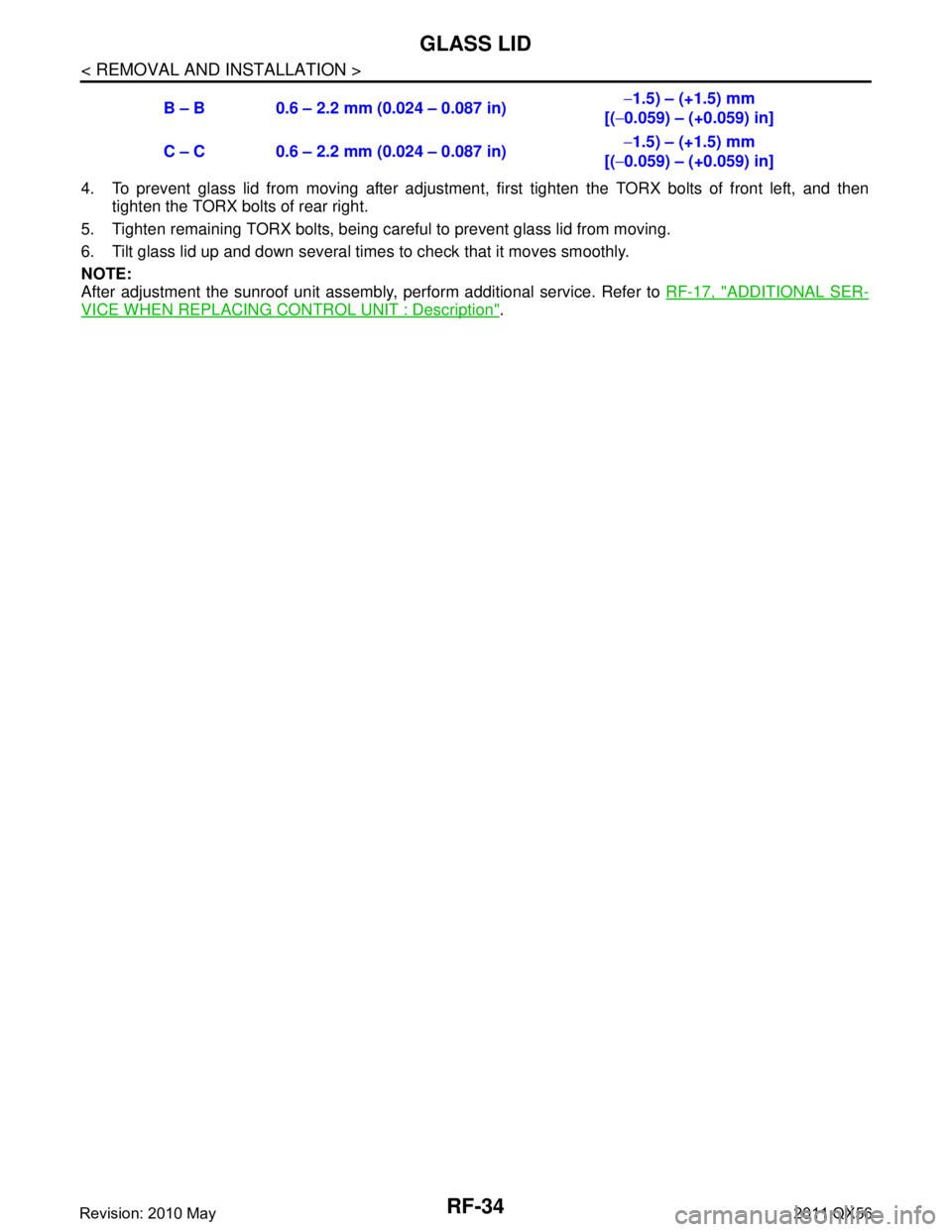
RF-34
< REMOVAL AND INSTALLATION >
GLASS LID
4. To prevent glass lid from moving after adjustment, first tighten the TORX bolts of front left, and then
tighten the TORX bolts of rear right.
5. Tighten remaining TORX bolts, being careful to prevent glass lid from moving.
6. Tilt glass lid up and down several times to check that it moves smoothly.
NOTE:
After adjustment the sunroof unit assembly, perform additional service. Refer to RF-17, "
ADDITIONAL SER-
VICE WHEN REPLACING CONTROL UNIT : Description".
B – B 0.6 – 2.2 mm (0.024 – 0.087 in)
−
1.5) – (+1.5) mm
[( −0.059) – (+0.059) in]
C – C 0.6 – 2.2 mm (0.024 – 0.087 in) −
1.5) – (+1.5) mm
[( −0.059) – (+0.059) in]
Revision: 2010 May2011 QX56
Page 4256 of 5598
RSU-1
SUSPENSION
C
DF
G H
I
J
K L
M
SECTION RSU
A
B
RSU
N
O PCONTENTS
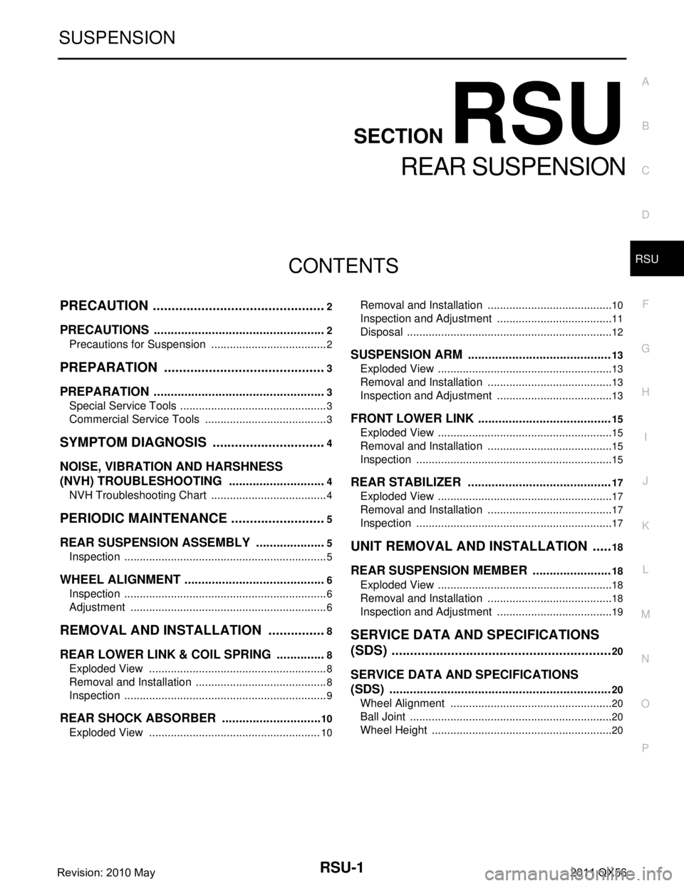
REAR SUSPENSION
PRECAUTION ................ ...............................2
PRECAUTIONS .............................................. .....2
Precautions for Suspension ................................ ......2
PREPARATION ............................................3
PREPARATION .............................................. .....3
Special Service Tools .......................................... ......3
Commercial Service Tools ........................................3
SYMPTOM DIAGNOSIS ...............................4
NOISE, VIBRATION AND HARSHNESS
(NVH) TROUBLESHOOTING ........................ .....
4
NVH Troubleshooting Chart ................................ ......4
PERIODIC MAINTENANCE ..........................5
REAR SUSPENSION ASSEMBLY ................ .....5
Inspection ............................................................ ......5
WHEEL ALIGNMENT ..........................................6
Inspection ............................................................ ......6
Adjustment ................................................................6
REMOVAL AND INSTALLATION ................8
REAR LOWER LINK & COIL SPRING .......... .....8
Exploded View .................................................... ......8
Removal and Installation ...........................................8
Inspection ..................................................................9
REAR SHOCK ABSORBER ..............................10
Exploded View .................................................... ....10
Removal and Installation ..................................... ....10
Inspection and Adjustment ......................................11
Disposal ...................................................................12
SUSPENSION ARM ..........................................13
Exploded View .........................................................13
Removal and Installation .........................................13
Inspection and Adjustment ......................................13
FRONT LOWER LINK .......................................15
Exploded View .........................................................15
Removal and Installation .........................................15
Inspection ................................................................15
REAR STABILIZER ..........................................17
Exploded View .........................................................17
Removal and Installation .........................................17
Inspection ................................................................17
UNIT REMOVAL AND INSTALLATION ......18
REAR SUSPENSION MEMBER .......................18
Exploded View ..................................................... ....18
Removal and Installation .........................................18
Inspection and Adjustment ......................................19
SERVICE DATA AND SPECIFICATIONS
(SDS) ............... .............................................
20
SERVICE DATA AND SPECIFICATIONS
(SDS) .................................................................
20
Wheel Alignment ................................................. ....20
Ball Joint ..................................................................20
Wheel Height ...........................................................20
Revision: 2010 May2011 QX56
Page 4258 of 5598
PREPARATIONRSU-3
< PREPARATION >
C
DF
G H
I
J
K L
M A
B
RSU
N
O P
PREPARATION
PREPARATION
Special Service ToolsINFOID:0000000006225657
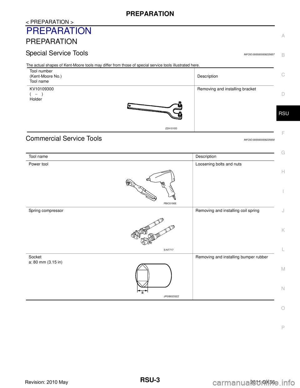
The actual shapes of Kent-Moore t ools may differ from those of special service tools illustrated here.
Commercial Service ToolsINFOID:0000000006225658
Tool number
(Kent-Moore No.)
Tool name Description
KV10109300
( − )
Holder Removing and installing bracket
ZZA1010D
Tool name
Description
Power tool Loosening bolts and nuts
Spring compressor Removing and installing coil spring
Socket
a: 80 mm (3.15 in) Removing and installing bumper rubber
PBIC0190E
S-NT717
JPEIB0233ZZ
Revision: 2010 May2011 QX56
Page 4261 of 5598
RSU-6
< PERIODIC MAINTENANCE >
WHEEL ALIGNMENT
WHEEL ALIGNMENT
InspectionINFOID:0000000006225661
DESCRIPTION
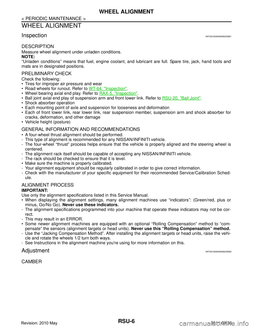
Measure wheel alignment under unladen conditions.
NOTE:
“Unladen conditions” means that fuel, engine coolant, and lubricant are full. Spare tire, jack, hand tools and
mats are in designated positions.
PRELIMINARY CHECK
Check the following:
Tires for improper air pressure and wear
Road wheels for runout. Refer to WT-64, "
Inspection".
Wheel bearing axial end play. Refer to RAX-5, "
Inspection".
Ball joint axial end play of suspension arm and front lower link. Refer to RSU-20, "
Ball Joint".
Shock absorber operation
Each mounting point of axle and suspension for looseness and deformation
Each of front lower link, rear lower link, rear suspension member, suspension arm and shock absorber for
cracks, deformation, and other damage
Vehicle height (posture)
GENERAL INFORMATION AND RECOMMENDATIONS
A four-wheel thrust alignment should be performed.
- This type of alignment is recomm ended for any NISSAN/INFINITI vehicle.
- The four-wheel “thrust” process helps ensure that t he vehicle is properly aligned and the steering wheel is
centered.
- The alignment rack itself should be capable of accepting any NISSAN/INFINITI vehicle.
- The rack should be checked to ensure that it is level.
Make sure the machine is properly calibrated.
- Your alignment equipment should be regularly calib rated in order to give correct information.
- Check with the manufacturer of your specific equi pment for their recommended Service/Calibration Sched-
ule.
ALIGNMENT PROCESS
IMPORTANT:
Use only the alignment specifications listed in this Service Manual.
When displaying the alignment settings, many alignment machines use “indicators”: (Green/red, plus or
minus, Go/No Go). Never use these indicators.
- The alignment specifications programmed into your machine that operate these indicators may not be cor-
rect.
- This may result in an ERROR.
Some newer alignment machines are equipped with an optional “Rolling Compensation” method to “com- pensate” the sensors (alignment targets or head units). Never use this “Rolling Compensation” method.
- Use the “Jacking Compensation Method”. After installi ng the alignment targets or head units, raise the vehi-
cle and rotate the wheels 1/2 turn both ways.
- See Instructions in the alignment machine you're using for more information on this.
AdjustmentINFOID:0000000006225662
CAMBER
Revision: 2010 May2011 QX56
Page 4263 of 5598
RSU-8
< REMOVAL AND INSTALLATION >
REAR LOWER LINK & COIL SPRING
REMOVAL AND INSTALLATION
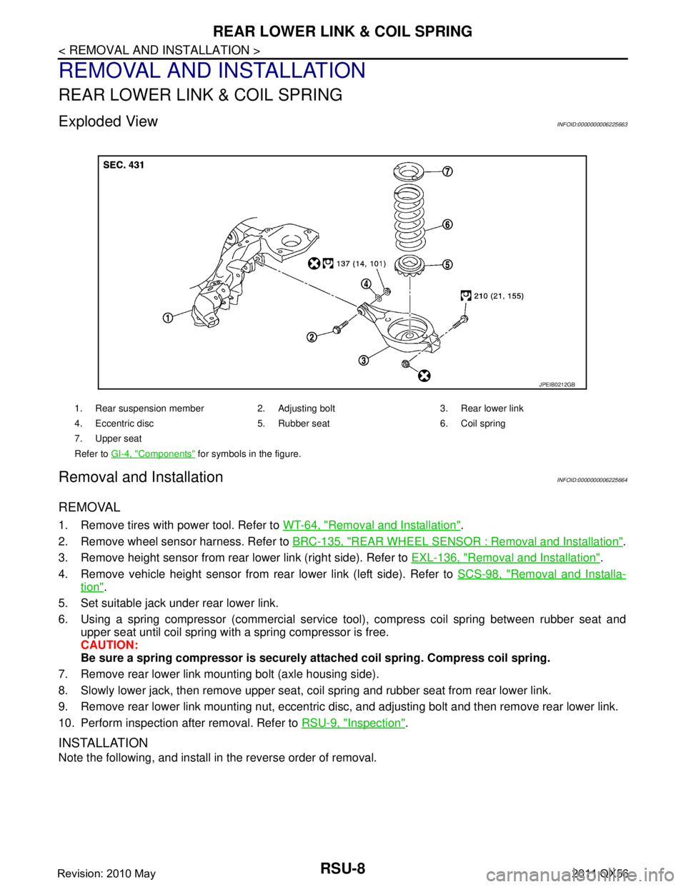
REAR LOWER LINK & COIL SPRING
Exploded ViewINFOID:0000000006225663
Removal and InstallationINFOID:0000000006225664
REMOVAL
1. Remove tires with power tool. Refer to WT-64, "Removal and Installation".
2. Remove wheel sensor harness. Refer to BRC-135, "
REAR WHEEL SENSOR : Removal and Installation".
3. Remove height sensor from rear lower link (right side). Refer to EXL-136, "
Removal and Installation".
4. Remove vehicle height sensor from rear lower link (left side). Refer to SCS-98, "
Removal and Installa-
tion".
5. Set suitable jack under rear lower link.
6. Using a spring compressor (commercial service tool), compress coil spring between rubber seat and upper seat until coil spring with a spring compressor is free.
CAUTION:
Be sure a spring compressor is securely at tached coil spring. Compress coil spring.
7. Remove rear lower link mounting bolt (axle housing side).
8. Slowly lower jack, then remove upper seat, co il spring and rubber seat from rear lower link.
9. Remove rear lower link mounting nut, eccentric disc, and adjusting bolt and then remove rear lower link.
10. Perform inspection after removal. Refer to RSU-9, "
Inspection".
INSTALLATION
Note the following, and install in the reverse order of removal.
1. Rear suspension member 2. Adjusting bolt 3. Rear lower link
4. Eccentric disc 5. Rubber seat 6. Coil spring
7. Upper seat
Refer to GI-4, "
Components" for symbols in the figure.
JPEIB0212GB
Revision: 2010 May2011 QX56
Page 4268 of 5598
SUSPENSION ARMRSU-13
< REMOVAL AND INSTALLATION >
C
DF
G H
I
J
K L
M A
B
RSU
N
O P
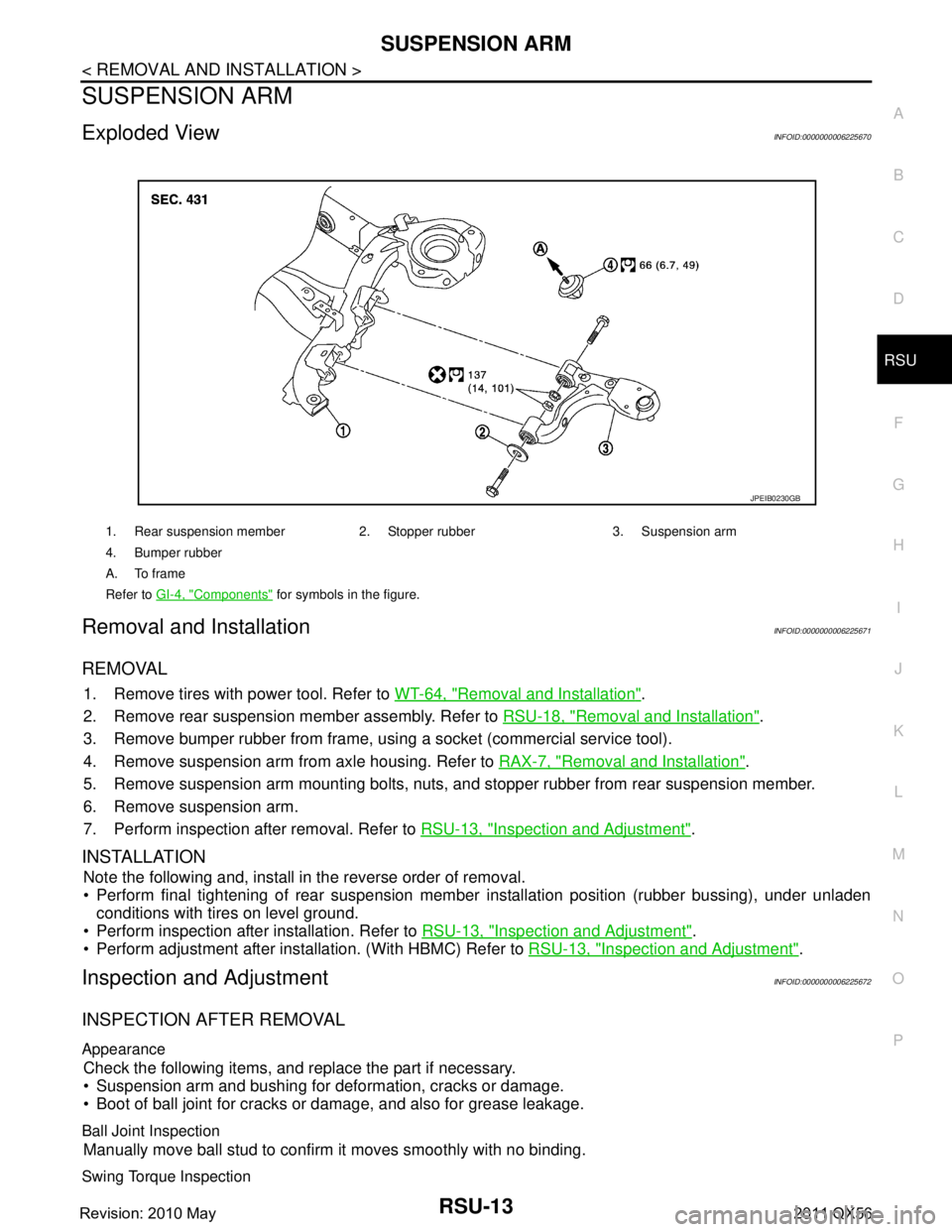
SUSPENSION ARM
Exploded ViewINFOID:0000000006225670
Removal and InstallationINFOID:0000000006225671
REMOVAL
1. Remove tires with power tool. Refer to WT-64, "Removal and Installation".
2. Remove rear suspension member assembly. Refer to RSU-18, "
Removal and Installation".
3. Remove bumper rubber from frame, usi ng a socket (commercial service tool).
4. Remove suspension arm from axle housing. Refer to RAX-7, "
Removal and Installation".
5. Remove suspension arm mounting bolts, nuts, and stopper rubber from rear suspension member.
6. Remove suspension arm.
7. Perform inspection after removal. Refer to RSU-13, "
Inspection and Adjustment".
INSTALLATION
Note the following and, install in the reverse order of removal.
Perform final tightening of rear suspension mem ber installation position (rubber bussing), under unladen
conditions with tires on level ground.
Perform inspection after installation. Refer to RSU-13, "
Inspection and Adjustment".
Perform adjustment after installation. (With HBMC) Refer to RSU-13, "
Inspection and Adjustment".
Inspection and AdjustmentINFOID:0000000006225672
INSPECTION AFTER REMOVAL
Appearance
Check the following items, and replace the part if necessary.
Suspension arm and bushing for deformation, cracks or damage.
Boot of ball joint for cracks or damage, and also for grease leakage.
Ball Joint Inspection
Manually move ball stud to confirm it moves smoothly with no binding.
Swing Torque Inspection
1. Rear suspension member 2. Stopper rubber 3. Suspension arm
4. Bumper rubber
A. To frame
Refer to GI-4, "
Components" for symbols in the figure.
JPEIB0230GB
Revision: 2010 May2011 QX56