window INFINITI QX56 2011 Factory Repair Manual
[x] Cancel search | Manufacturer: INFINITI, Model Year: 2011, Model line: QX56, Model: INFINITI QX56 2011Pages: 5598, PDF Size: 94.53 MB
Page 1521 of 5598

DOOR MIRROR DEFOGGERDEF-29
< DTC/CIRCUIT DIAGNOSIS >
C
DE
F
G H
I
J
K
M A
B
DEF
N
O P
DOOR MIRROR DEFOGGER
DescriptionINFOID:0000000006299442
Heats the heating wire with the power supply from t he rear window defogger relay to prevent the door mirror
from fogging up.
Component Function CheckINFOID:0000000006299443
1.CHECK DOOR MIRROR DEFOGGER
1. Perform IPDM E/R Active Test (“REAR DEFOGGER”) using CONSULT-III.
2. Touch “ON”.
3. Check that both side door mirror glasses are getting warmer.
Is the inspection result normal?
YES >> Door mirror defogger is OK.
NO >> Refer to DEF-29, "
Diagnosis Procedure"
Diagnosis ProcedureINFOID:0000000006299444
1.CHECK FUSE
1. Turn ignition switch OFF.
2. Check 10A fuse [No.80, loca ted in fuse block (J/B)].
Is the inspection result normal?
YES >> GO TO 2.
NO >> Replace the blown fuse after repairing the affected circuit if a fuse is blown.
2.CHECK DOOR MIRROR DEFOGGER CIRCUIT
1. Disconnect IPDM E/R connector and door mirror (both sides) connector.
2. Check continuity between IPDM E/R harness connec tor and door mirror (driver side) harness connector.
3. Check continuity between IPDM E/R harness connector and ground.
Is the inspection result normal?
YES >> GO TO 3.
NO >> Repair or replace harness.
3.CHECK INTERMITTENT INCIDENT
Check intermittent incident.
Refer to GI-40, "
Intermittent Incident".
>> INSPECTION END
IPDM E/R Door mirro r (driver side)
Continuity
Connector Terminal Connector Terminal
E11 14 D3 7 Existed
IPDM E/R GroundContinuity
Connector Terminal
E11 14 Not existed
Revision: 2010 May2011 QX56
Page 1522 of 5598

DEF-30
< DTC/CIRCUIT DIAGNOSIS >
DRIVER SIDE DOOR MIRROR DEFOGGER
DRIVER SIDE DOOR MIRROR DEFOGGER
DescriptionINFOID:0000000006299445
Heats the heating wire with the power supply from the rear window defogger relay to prevent the door mirror
from fogging up.
Component Function CheckINFOID:0000000006299446
1.CHECK DRIVER SIDE DOOR MIRROR DEFOGGER
1. Perform IPDM E/R Active Test (“REAR DEFOGGER”) using CONSULT-III.
2. Touch “ON”.
3. Check that the driver side door mirror glass is getting warmer.
Is the inspection result normal?
YES >> Driver side door mirror defogger is OK.
NO >> Refer to DEF-30, "
Diagnosis Procedure"
Diagnosis ProcedureINFOID:0000000006299447
1.CHECK POWER SUPPLY CIRCUIT
1. Turn ignition switch OFF.
2. Disconnect door mirror (driver side) connector.
3. Turn ignition switch ON.
4. Check voltage between door mirror (driver side) harness connector and ground.
Is the inspection result normal?
YES >> GO TO 2.
NO >> Repair or replace harness.
2.CHECK GROUND CIRCUIT
1. Turn ignition switch OFF.
2. Check continuity between door mirror (driver side) harness connector and ground.
Is the inspection result normal?
YES >> Replace door mirror glass (driver side).
NO >> Repair or replace harness.
(+)
(–) Condition Voltage (V)
(Approx.)
Door mirror (driver side)
Connector Terminal
D3 7 Ground Rear window defogger
switchON Battery voltage
OFF 0
Door mirror (driver side)
GroundContinuity
Connector Terminal
D3 19 Existed
Revision: 2010 May2011 QX56
Page 1523 of 5598

PASSENGER SIDE DOOR MIRROR DEFOGGERDEF-31
< DTC/CIRCUIT DIAGNOSIS >
C
DE
F
G H
I
J
K
M A
B
DEF
N
O P
PASSENGER SIDE DOOR MIRROR DEFOGGER
DescriptionINFOID:0000000006299448
Heats the heating wire with the power supply from t he rear window defogger relay to prevent the door mirror
from fogging up.
Component Function CheckINFOID:0000000006299449
1.CHECK PASSENGER SIDE DOOR MIRROR DEFOGGER
1. Perform IPDM E/R Active Test (“REAR DEFOGGER”) using CONSULT-III.
2. Touch “ON”.
3. Check that the passenger side door mirror glass is getting warmer.
Is the inspection result normal?
YES >> Passenger side door mirror defogger is OK.
NO >> Refer to DEF-31, "
Diagnosis Procedure"
Diagnosis ProcedureINFOID:0000000006299450
1.CHECK POWER SUPPLY CIRCUIT
1. Turn ignition switch OFF.
2. Disconnect door mirror (passenger side) connector.
3. Turn ignition switch ON.
4. Check voltage between door mirror (passenger side) harness connector and ground.
Is the inspection result normal?
YES >> GO TO 2.
NO >> Repair or replace harness.
2.CHECK GROUND CIRCUIT
1. Turn ignition switch OFF.
2. Check continuity between door mirror (passenger side) harness connector and ground.
Is the inspection result normal?
YES >> Replace door mirror glass (passenger side).
NO >> Repair or replace harness.
(+)
(–) Condition Voltage (V)
(Approx.)
Door mirror (passenger side)
Connector Terminal
D23 7 Ground Rear window defogger
switchON Battery voltage
OFF 0
Door mirror (passenger side)
GroundContinuity
Connector Terminal
D23 19 Existed
Revision: 2010 May2011 QX56
Page 1524 of 5598

DEF-32
< DTC/CIRCUIT DIAGNOSIS >
WIPER DEICER RELAY
WIPER DEICER RELAY
Component Function CheckINFOID:0000000006299451
1.CHECK WIPER DEICER RELAY POWER SUPPLY CIRCUIT
1. Select Active Test (“REAR DEFOGGER”) mode of “BCM” using CONSULT-III.
2. Touch “ON”.
3. Check that the front window heating wire is getting warmer.
Is the inspection result normal?
YES >> Wiper deicer relay power supply circuit function is OK.
NO >> Refer to DEF-32, "
Diagnosis Procedure".
Diagnosis ProcedureINFOID:0000000006299452
1.CHECK WIPER DEICER CIRCUIT 1
1. Turn ignition switch ON.
2. Check voltage between wiper deicer relay harness connector and ground.
Is the inspection result normal?
YES >> GO TO 3.
NO >> GO TO 2.
2.CHECK WIPER DEICER CIRCUIT 2
1. Turn ignition switch OFF.
2. Disconnect wiper deicer relay and IPDM E/R connector.
3. Check continuity between wiper deicer relay terminal connector and IPDM E/R harness connector.
Is the inspection result normal?
YES >> GO TO 6.
NO >> Repair or replace harness.
3.CHECK WIPER DEICER CIRCUIT 3
Check voltage between wiper deicer relay harness connector and ground.
Is the inspection result normal?
YES >> GO TO 4.
NO >> Repair or replace harness.
4.CHECK WIPER DEICER RELAY GROUND CIRCUIT
1. Turn ignition switch OFF.
2. Disconnect wiper deicer relay connector.
3. Check continuity between wiper deicer relay terminal connector and ground.
(+)
(–) Condition Voltage (V)
(Approx.)
Wiper deicer relay
Connector Terminal
E23 1 Ground Rear window defogger switch: ON Battery voltage
Rear window defogger switch: OFF 0
Wiper deicer relay IPDM E/R
Continuity
Connector Terminal Connector Terminal
E23 1 E11 14 Existed
(+) (–)Voltage (V)
(Approx.)
Wiper deicer relay
Connector Terminal E23 3 Ground Battery voltage
Revision: 2010 May2011 QX56
Page 1526 of 5598

DEF-34
< DTC/CIRCUIT DIAGNOSIS >
WIPER DEICER
WIPER DEICER
Component Function CheckINFOID:0000000006299454
1.CHECK WIPER DEICER
1. Select Active Test (“REAR DEFOGGER”) mode of “BCM” using CONSULT-III.
2. Touch “ON”.
3. Check that the front window heating wire is getting warmer.
Is the inspection result normal?
YES >> Wiper deicer is OK.
NO >> Refer to DEF-34, "
Diagnosis Procedure"
Diagnosis ProcedureINFOID:0000000006299455
1.CHECK FUSE
1. Turn ignition switch OFF.
2. Check 15 A fuse [No.75, located in fuse block (J/B)]
Is the inspection result normal?
YES >> GO TO 2.
NO >> Replace the blown fuse after repairing the affected circuit if a fuse is blown.
2.CHECK POWER SUPPLY CIRCUIT
1. Turn ignition switch ON.
2. Check voltage between wiper deicer harness connector and ground.
Is the inspection result normal?
YES >> GO TO 3.
NO >> GO TO 4.
3.CHECK GROUND CIRCUIT
1. Turn ignition switch OFF.
2. Disconnect wiper deicer connector.
3. Check continuity between wiper deicer harness connector and ground.
Is the inspection result normal?
YES >> GO TO 5.
NO >> Repair or replace harness between rear window defogger and ground.
4.CHECK WIPER DEICER CIRCUIT
1. Turn ignition switch OFF.
2. Disconnect wiper deicer relay connector and wiper deicer connector.
3. Check continuity between wiper deicer relay harness connector and wiper deicer harness connector.
(+)
(–) Condition Voltage (V)
(Approx.)
Wiper deicer
Connector Terminal
E40 1 Ground Rear window defogger switch: ON Battery voltage
Rear window defogger switch: OFF 0
Wiper deicer
GroundContinuity
Connector Terminal
E40 2 Existed
Revision: 2010 May2011 QX56
Page 1528 of 5598

DEF-36
< SYMPTOM DIAGNOSIS >
REAR WINDOW DEFOGGER DOES NOT OPERATE
SYMPTOM DIAGNOSIS
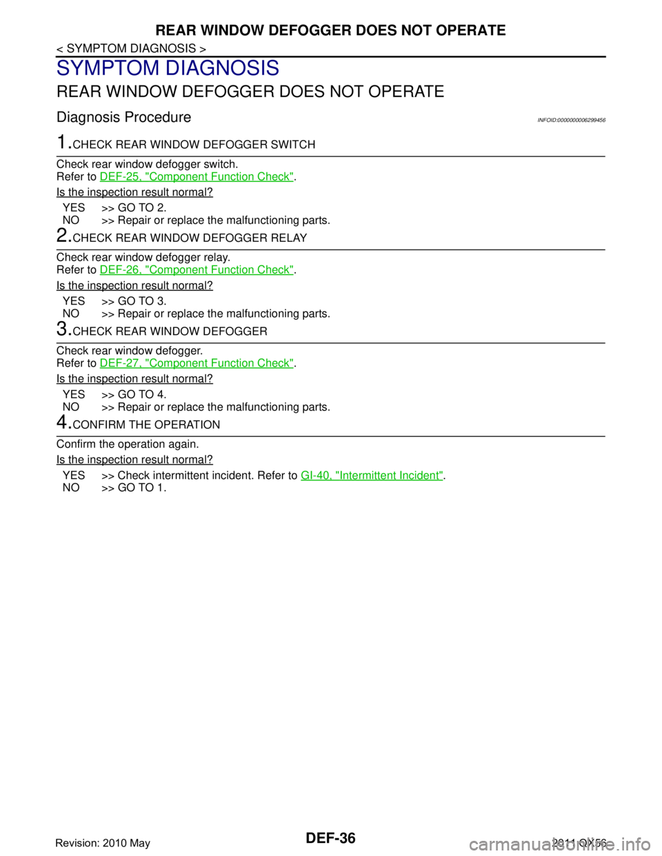
REAR WINDOW DEFOGGER DOES NOT OPERATE
Diagnosis ProcedureINFOID:0000000006299456
1.CHECK REAR WINDOW DEFOGGER SWITCH
Check rear window defogger switch.
Refer to DEF-25, "
Component Function Check".
Is the inspection result normal?
YES >> GO TO 2.
NO >> Repair or replace the malfunctioning parts.
2.CHECK REAR WINDOW DEFOGGER RELAY
Check rear window defogger relay.
Refer to DEF-26, "
Component Function Check".
Is the inspection result normal?
YES >> GO TO 3.
NO >> Repair or replace the malfunctioning parts.
3.CHECK REAR WINDOW DEFOGGER
Check rear window defogger.
Refer to DEF-27, "
Component Function Check".
Is the inspection result normal?
YES >> GO TO 4.
NO >> Repair or replace the malfunctioning parts.
4.CONFIRM THE OPERATION
Confirm the operation again.
Is the inspection result normal?
YES >> Check intermittent incident. Refer to GI-40, "Intermittent Incident".
NO >> GO TO 1.
Revision: 2010 May2011 QX56
Page 1529 of 5598

REAR WINDOW DEFOGGER AND DOOR MIRROR DEFOGGER DO NOT OPER-
ATE.
DEF-37
< SYMPTOM DIAGNOSIS >
C
D E
F
G H
I
J
K
M A
B
DEF
N
O P
REAR WINDOW DEFOGGER AND DO OR MIRROR DEFOGGER DO NOT
OPERATE.
Diagnosis ProcedureINFOID:0000000006299457
1.CHECK REAR WINDOW DEFOGGER SWITCH
Check rear window defogger switch.
Refer to DEF-25, "
Component Function Check".
Is the inspection result normal?
YES >> GO TO 2.
NO >> Repair or replace the malfunctioning parts.
2.CHECK REAR WINDOW DEFOGGER RELAY
Check rear window defogger relay.
Refer to DEF-26, "
Component Function Check".
Is the inspection result normal?
YES >> GO TO 3.
NO >> Repair or replace the malfunctioning parts.
3.CHECK REAR WINDOW DEFOGGER
Check rear window defogger.
Refer to DEF-27, "
Component Function Check".
Is the inspection result normal?
YES >> GO TO 4.
NO >> Repair or replace the malfunctioning parts.
4.CONFIRM THE OPERATION
Confirm the operation again.
Is the inspection result normal?
YES >> Check intermittent incident. Refer to GI-40, "Intermittent Incident".
NO >> GO TO 1.
Revision: 2010 May2011 QX56
Page 1530 of 5598

DEF-38
< SYMPTOM DIAGNOSIS >
REAR WINDOW DEFOGGER DOES NOT OPERATE BUT BOTH DOOR MIRROR
DEFOGGERS OPERATE.
REAR WINDOW DEFOGGER DOES NOT OPERATE BUT BOTH DOOR
MIRROR DEFOGGERS OPERATE.
Diagnosis ProcedureINFOID:0000000006299458
1.CHECK REAR WINDOW DEFOGGER
Check rear window defogger.
Refer to DEF-27, "
Component Function Check".
Is the inspection result normal?
YES >> GO TO 2.
NO >> Repair or replace the malfunctioning parts.
2.CONFIRM THE OPERATION
Confirm the operation again
Is the inspection result normal?
YES >> Check intermittent incident. Refer to GI-40, "Intermittent Incident".
NO >> GO TO 1.
Revision: 2010 May2011 QX56
Page 1534 of 5598

DEF-42
< SYMPTOM DIAGNOSIS >
ON IS NOT DISPLAYED WHEN PRESSING REAR WINDOW DEFOGGER
SWITCH BUT IT IS OPERATED
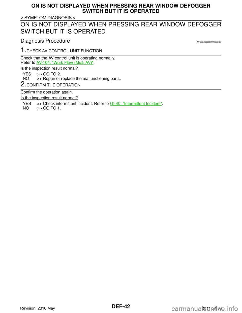
ON IS NOT DISPLAYED WHEN PR ESSING REAR WINDOW DEFOGGER
SWITCH BUT IT IS OPERATED
Diagnosis ProcedureINFOID:0000000006299466
1.CHECK AV CONTROL UNIT FUNCTION
Check that the AV control unit is operating normally.
Refer to AV-104, "
Work Flow (Multi AV)".
Is the inspection result normal?
YES >> GO TO 2.
NO >> Repair or replace the malfunctioning parts.
2.CONFIRM THE OPERATION
Confirm the operation again.
Is the inspection result normal?
YES >> Check intermittent incident. Refer to GI-40, "Intermittent Incident".
NO >> GO TO 1.
Revision: 2010 May2011 QX56
Page 1548 of 5598

DLK-12
< SYSTEM DESCRIPTION >
COMPONENT PARTS
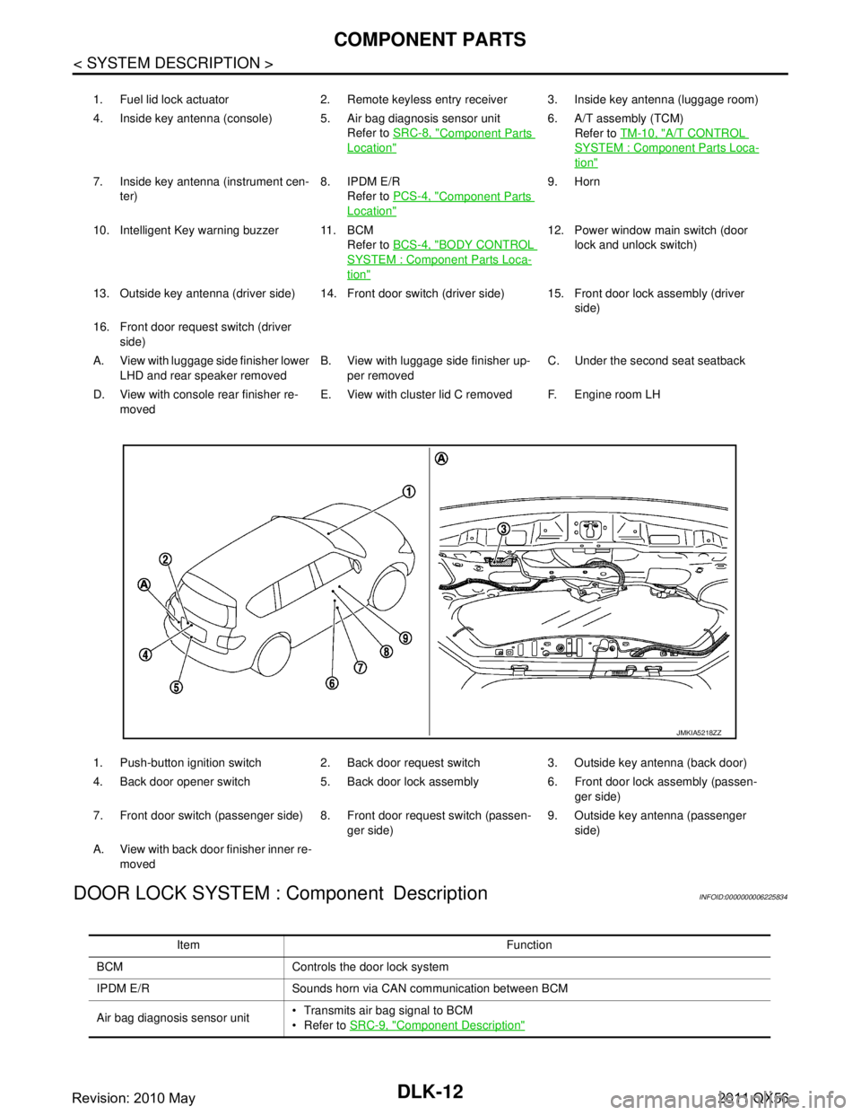
DOOR LOCK SYSTEM : Component Description
INFOID:0000000006225834
1. Fuel lid lock actuator 2. Remote keyless entry receiver 3. Inside key antenna (luggage room)
4. Inside key antenna (console) 5. Air bag diagnosis sensor unit Refer to SRC-8, "
Component Parts
Location"
6. A/T assembly (TCM)
Refer to TM-10, "
A/T CONTROL
SYSTEM : Component Parts Loca-
tion"
7. Inside key antenna (instrument cen-
ter) 8. IPDM E/R
Refer to PCS-4, "
Component Parts
Location"
9. Horn
10. Intelligent Key warning buzzer 11. BCM Refer to BCS-4, "
BODY CONTROL
SYSTEM : Component Parts Loca-
tion"
12. Power window main switch (door
lock and unlock switch)
13. Outside key antenna (driver side) 14. Front door switch (driver side) 15. Front door lock assembly (driver side)
16. Front door request switch (driver side)
A. View with luggage side finisher lower LHD and rear speaker removed B. View with luggage side finisher up-
per removed C. Under the second seat seatback
D. View with console rear finisher re- moved E. View with cluster lid C removed F. Engine room LH
1. Push-button ignition switch 2. Back door request switch 3. Outside key antenna (back door)
4. Back door opener switch 5. Back door lock assembly 6. Front door lock assembly (passen- ger side)
7. Front door switch (passenger side) 8. Front door request switch (passen- ger side)9. Outside key antenna (passenger
side)
A. View with back door finisher inner re- moved
JMKIA5218ZZ
Item Function
BCM Controls the door lock system
IPDM E/R Sounds horn via CAN communication between BCM
Air bag diagnosis sensor unit Transmits air bag signal to BCM
Refer to
SRC-9, "
Component Description"
Revision: 2010 May2011 QX56