air condition INFINITI QX56 2011 Factory Service Manual
[x] Cancel search | Manufacturer: INFINITI, Model Year: 2011, Model line: QX56, Model: INFINITI QX56 2011Pages: 5598, PDF Size: 94.53 MB
Page 4242 of 5598
RF-28
< SYMPTOM DIAGNOSIS >
SQUEAK AND RATTLE TROUBLE DIAGNOSES
The following materials, not found in the kit, can also be used to repair squeaks and rattles.
UHMW (TEFLON) TAPE
Insulates where slight movement is present. Ideal for instrument panel applications.
SILICONE GREASE
Used in place of UHMW tape that is visible or does not fit. Only lasts a few months.
SILICONE SPRAY
Used when grease cannot be applied.
DUCT TAPE
Used to eliminate movement.
CONFIRM THE REPAIR
After repair is complete, test drive the vehicle to confir m that the cause of noise is repaired by test driving the
vehicle. Operate the vehicle under the same conditions as when the noise originally occurred. Refer to the
notes on the Diagnostic Worksheet.
Inspection ProcedureINFOID:0000000006367804
Refer to Table of Contents for specific component removal and installation information.
INSTRUMENT PANEL
Most incidents are caused by contact and movement between:
1. The cluster lid A and instrument panel
2. Acrylic lens and combination meter housing
3. Instrument panel to front pillar garnish
4. Instrument panel to windshield
5. Instrument panel mounting pins
6. Wiring harnesses behind the combination meter
7. A/C defroster duct and duct joint These incidents can usually be located by tapping or moving the components to duplicate the noise or by
pressing on the components while driving to stop the noise. Most of these incidents can be repaired by
applying felt cloth tape or silicon spray (in hard to reach areas). Urethane pads can be used to insulate
wiring harness.
CAUTION:
Never use silicone spray to isolate a squeak or ra ttle. If the area is saturated with silicone, the
recheck of repair becomes impossible.
CENTER CONSOLE
Components to check include:
1. Shifter assembly cover to finisher
2. A/C control unit and cluster lid C
3. Wiring harnesses behind audio and A/C control unit
The instrument panel repair and isolation pr ocedures also apply to the center console.
DOORS
Check the following items:
1. Finisher and inner panel making a slapping noise
2. Inside handle escutcheon connection to door finisher
3. Wiring harnesses tapping
4. Door striker out of alignment causing a popping noise on starts and stops
Tapping, moving the components, or pressing on them wh ile driving to duplicate the conditions can isolate
many of these incidents. The areas can usually be insula ted with felt cloth tape or insulator foam blocks from
the NISSAN Squeak and Rattle Kit (J-43980) to repair the noise.
TRUNK
Trunk noises are often caused by a loose jack or loose items put into the trunk by the customer.
In addition check for the following items:
1. Trunk lid dumpers out of adjustment
2. Trunk lid striker out of adjustment
Revision: 2010 May2011 QX56
Page 4243 of 5598

SQUEAK AND RATTLE TROUBLE DIAGNOSESRF-29
< SYMPTOM DIAGNOSIS >
C
DE
F
G H
I
J
L
M A
B
RF
N
O P
3. Trunk lid torsion bars knocking together
4. A loose license plate or bracket
Most of these incidents can be repaired by adjusting, se curing, or insulating the item(s) or component(s) caus-
ing the noise.
SUNROOF/HEADLINING
Noises in the sunroof / headlining area can of ten be traced to one of the following items:
1. Sunroof lid, rail, linkage, or seals making a rattle or light knocking noise
2. Sunvisor shaft shaking in the holder
3. Front or rear windshield touching headlining and squeaking
Again, pressing on the components to stop the noise while duplicating the conditions can isolate most of these
incidents. Repairs usually consist of insulating with felt cloth tape.
SEATS
When isolating seat noise it is important to note the position the seat is in and the load placed on the seat
when the noise occurs. These conditions should be duplic ated when verifying and isolating the cause of the
noise.
Causes of seat noise include:
1. Headrest rods and holder
2. A squeak between the seat pad cushion and frame
3. The rear seatback lock and bracket
These noises can be isolated by moving or pressing on the suspected components while duplicating the con-
ditions under which the noise occurs. Most of thes e incidents can be repaired by repositioning the component
or applying urethane tape to the contact area.
UNDERHOOD
Some interior noise may be caused by components under the hood or on the engine wall. The noise is then
transmitted into the passenger compartment.
Causes of transmitted underhood noise include:
1. Any component mounted to the engine wall
2. Components that pass through the engine wall
3. Engine wall mounts and connectors
4. Loose radiator mounting pins
5. Hood bumpers out of adjustment
6. Hood striker out of adjustment
These noises can be difficult to isolate since they cannot be reached from the interior of the vehicle. The best
method is to secure, move, or insulate one component at a time and test drive the vehicle. Also, engine RPM
or load can be changed to isolate the noise. Repairs c an usually be made by moving, adjusting, securing, or
insulating the component causing the noise.
Revision: 2010 May2011 QX56
Page 4261 of 5598
RSU-6
< PERIODIC MAINTENANCE >
WHEEL ALIGNMENT
WHEEL ALIGNMENT
InspectionINFOID:0000000006225661
DESCRIPTION
Measure wheel alignment under unladen conditions.
NOTE:
“Unladen conditions” means that fuel, engine coolant, and lubricant are full. Spare tire, jack, hand tools and
mats are in designated positions.
PRELIMINARY CHECK
Check the following:
Tires for improper air pressure and wear
Road wheels for runout. Refer to WT-64, "
Inspection".
Wheel bearing axial end play. Refer to RAX-5, "
Inspection".
Ball joint axial end play of suspension arm and front lower link. Refer to RSU-20, "
Ball Joint".
Shock absorber operation
Each mounting point of axle and suspension for looseness and deformation
Each of front lower link, rear lower link, rear suspension member, suspension arm and shock absorber for
cracks, deformation, and other damage
Vehicle height (posture)
GENERAL INFORMATION AND RECOMMENDATIONS
A four-wheel thrust alignment should be performed.
- This type of alignment is recomm ended for any NISSAN/INFINITI vehicle.
- The four-wheel “thrust” process helps ensure that t he vehicle is properly aligned and the steering wheel is
centered.
- The alignment rack itself should be capable of accepting any NISSAN/INFINITI vehicle.
- The rack should be checked to ensure that it is level.
Make sure the machine is properly calibrated.
- Your alignment equipment should be regularly calib rated in order to give correct information.
- Check with the manufacturer of your specific equi pment for their recommended Service/Calibration Sched-
ule.
ALIGNMENT PROCESS
IMPORTANT:
Use only the alignment specifications listed in this Service Manual.
When displaying the alignment settings, many alignment machines use “indicators”: (Green/red, plus or
minus, Go/No Go). Never use these indicators.
- The alignment specifications programmed into your machine that operate these indicators may not be cor-
rect.
- This may result in an ERROR.
Some newer alignment machines are equipped with an optional “Rolling Compensation” method to “com- pensate” the sensors (alignment targets or head units). Never use this “Rolling Compensation” method.
- Use the “Jacking Compensation Method”. After installi ng the alignment targets or head units, raise the vehi-
cle and rotate the wheels 1/2 turn both ways.
- See Instructions in the alignment machine you're using for more information on this.
AdjustmentINFOID:0000000006225662
CAMBER
Revision: 2010 May2011 QX56
Page 4264 of 5598
REAR LOWER LINK & COIL SPRINGRSU-9
< REMOVAL AND INSTALLATION >
C
DF
G H
I
J
K L
M A
B
RSU
N
O P
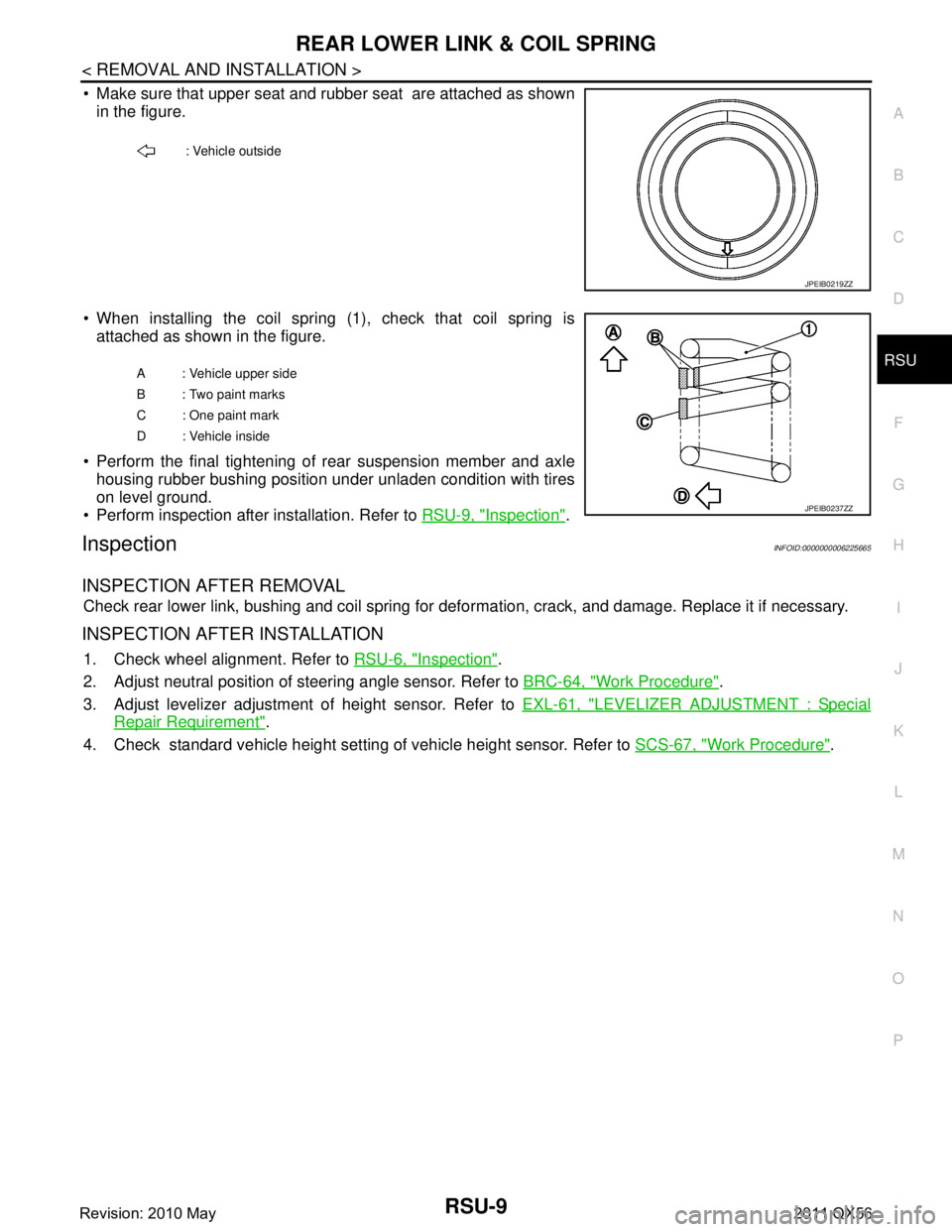
Make sure that upper seat and rubber seat are attached as shown in the figure.
When installing the coil spring (1), check that coil spring is attached as shown in the figure.
Perform the final tightening of rear suspension member and axle housing rubber bushing position under unladen condition with tires
on level ground.
Perform inspection after installation. Refer to RSU-9, "
Inspection".
InspectionINFOID:0000000006225665
INSPECTION AFTER REMOVAL
Check rear lower link, bushing and coil spring for defor mation, crack, and damage. Replace it if necessary.
INSPECTION AFTER INSTALLATION
1. Check wheel alignment. Refer to RSU-6, "Inspection".
2. Adjust neutral position of steering angle sensor. Refer to BRC-64, "
Work Procedure".
3. Adjust levelizer adjustment of height sensor. Refer to EXL-61, "
LEVELIZER ADJUSTMENT : Special
Repair Requirement".
4. Check standard vehicle height setting of vehicle height sensor. Refer to SCS-67, "
Work Procedure".
: Vehicle outside
JPEIB0219ZZ
A : Vehicle upper side
B : Two paint marks
C : One paint mark
D : Vehicle inside
JPEIB0237ZZ
Revision: 2010 May2011 QX56
Page 4266 of 5598
REAR SHOCK ABSORBERRSU-11
< REMOVAL AND INSTALLATION >
C
DF
G H
I
J
K L
M A
B
RSU
N
O P
Inadvertent piping removal causes fluid to splatter.
2. Remove tires with power tool. Refer to WT-64, "
Removal and Installation".
3. Remove height sensor from rear lower link (right side). Refer to EXL-136, "
Removal and Installation".
4. Remove vehicle height sensor from rear lower link (left side). Refer to SCS-98, "
Removal and Installa-
tion".
5. Remove air tube from shock absorber assembly. Refer to SCS-95, "
Removal and Installation".
6. Remove middle tube assembly from shock absorber assembly. (With HBMC) Refer to SCS-44, "
REAR
TUBE ASSEMBLY : Removal and Installation".
7. Remove shock absorber mounting bolt (lower side).
8. Remove piston rod lock nut.
9. Remove bracket, bushings, and shock absorber. (With HBMC)
10. Remove washers, bushings, and shock absorber. (Without HBMC)
11. Perform inspection after removal. Refer to RSU-11, "
Inspection and Adjustment".
INSTALLATION
Note the following, and install in the reverse order of removal.
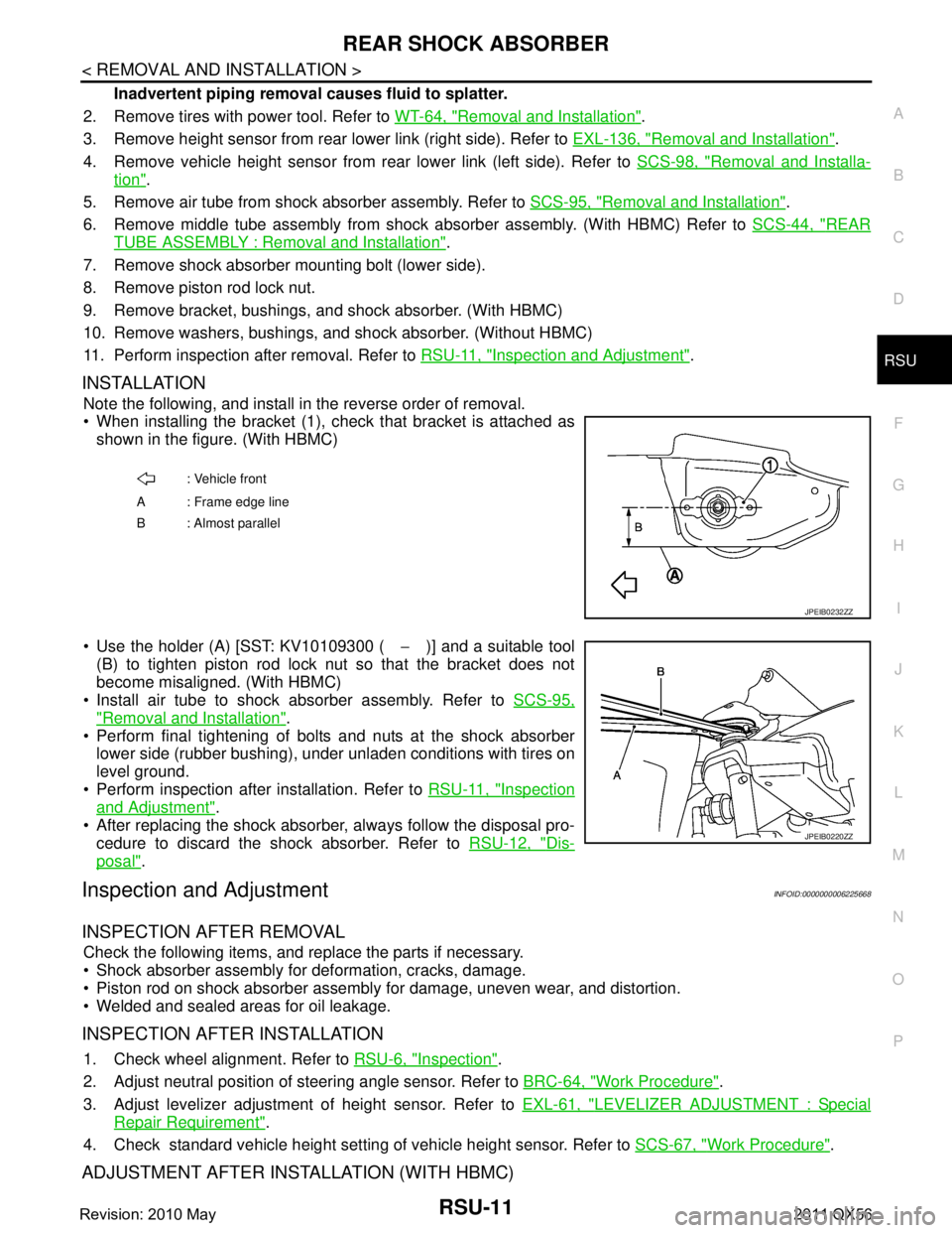
When installing the bracket (1), check that bracket is attached as
shown in the figure. (With HBMC)
Use the holder (A) [SST: KV10109300 ( −)] and a suitable tool
(B) to tighten piston rod lock nut so that the bracket does not
become misaligned. (With HBMC)
Install air tube to shock absorber assembly. Refer to SCS-95,
"Removal and Installation".
Perform final tightening of bolts and nuts at the shock absorber
lower side (rubber bushing), under unladen conditions with tires on
level ground.
Perform inspection after installation. Refer to RSU-11, "
Inspection
and Adjustment".
After replacing the shock absorber, always follow the disposal pro- cedure to discard the shock absorber. Refer to RSU-12, "
Dis-
posal".
Inspection and AdjustmentINFOID:0000000006225668
INSPECTION AFTER REMOVAL
Check the following items, and replace the parts if necessary.
Shock absorber assembly for deformation, cracks, damage.
Piston rod on shock absorber assembly for damage, uneven wear, and distortion.
Welded and sealed areas for oil leakage.
INSPECTION AFTER INSTALLATION
1. Check wheel alignment. Refer to RSU-6, "Inspection".
2. Adjust neutral position of steering angle sensor. Refer to BRC-64, "
Work Procedure".
3. Adjust levelizer adjustment of height sensor. Refer to EXL-61, "
LEVELIZER ADJUSTMENT : Special
Repair Requirement".
4. Check standard vehicle height setting of vehicle height sensor. Refer to SCS-67, "
Work Procedure".
ADJUSTMENT AFTER INSTALLATION (WITH HBMC)
: Vehicle front
A : Frame edge line
B: Almost parallel
JPEIB0232ZZ
JPEIB0220ZZ
Revision: 2010 May2011 QX56
Page 4274 of 5598
REAR SUSPENSION MEMBERRSU-19
< UNIT REMOVAL AND INSTALLATION >
C
DF
G H
I
J
K L
M A
B
RSU
N
O P
16. Remove final drive. Refer to DLN-201, "Removal and Installation".
17. Remove rear tube assembly A and rear tube assembly B. (With HBMC) Refer to SCS-44, "
REAR TUBE
ASSEMBLY : Removal and Installation".
18. Set suitable jack under rear suspension member.
19. Slowly lower jack, then remove rear suspension member, suspension arm, front lower link, wheel hub and housing from vehicle as a unit.
20. Remove mounting bolts and nuts, then remove suspension arm, front lower link, wheel hub and housing from rear suspension member.
21. Perform inspection after removal. Refer to RSU-19, "
Inspection and Adjustment".
INSTALLATION
Note the following, and install in the reverse order of the removal.
Perform the final tightening of each of parts under unladen conditions, which were removed when removing
rear suspension assembly.
Perform inspection after installation. Refer to RSU-19, "
Inspection and Adjustment".
Perform adjustment after installation. (With HBMC) Refer to RSU-19, "
Inspection and Adjustment".
Inspection and AdjustmentINFOID:0000000006225678
INSPECTION AFTER REMOVAL
Check rear suspension member for deformation, cracks, or any other damage. Replace if necessary.
INSPECTION AFTER INSTALLATION
1. Adjust parking brake operation (stroke). Refer to PB-3, "Inspection and Adjustment".
2. Check wheel alignment. Refer to RSU-6, "
Inspection".
3. Adjust neutral position of steering angle sensor. Refer to BRC-64, "
Work Procedure".
4. Adjust levelizer adjustment of height sensor. Refer to EXL-61, "
LEVELIZER ADJUSTMENT : Special
Repair Requirement".
5. Check standard vehicle height setting of vehicle height sensor. Refer to SCS-67, "
Work Procedure".
6. Check wheel sensor harness for proper connection. Refer to BRC-135, "
REAR WHEEL SENSOR :
Exploded View"
ADJUSTMENT AFTER INSTALLATION (WITH HBMC)
Bleed air from the HBMC. Refer to SCS-18, "Work Procedure".
Revision: 2010 May2011 QX56
Page 4303 of 5598

SBC-6
< SYSTEM DESCRIPTION >
COMPONENT PARTS
Component Description
INFOID:0000000006237876
A. View with instrument driver lower cov- er removed B. Combination switch C. View with center pillar lower garnish
removed (driver side)
D. View with center pillar lower garnish re- moved (passenger side)
Component Function
ABS actuator and electric unit (control unit) ABS operation signal is rece
ived from ABS actuator and el ectric unit (control unit)
via CAN communication.
ADAS control unit Intelligent brake assistance operation signal is received from ADAS control unit
via CAN communication.
Air bag diagnosis sensor unit Detects a collision and supplies power supply for deployment to air bag module
and pre-tensioner seat belt.
Performs the deploy judgement of passenger air bag based on the information from Occupant Detection System control unit
BCM Ignition ON signal, sleep/wake up signal, and door switch signal are received
from BCM via CAN communication.
Brake pedal stroke sensor It changes voltage according to brake pedal depressed amount and sends the
signal to pre-crash seat belt control unit.
There are 2 signals (brake pedal stroke sensor 1 and 2) sent from the brake
pedal stroke sensor. Pre-crash seat belt control unit judges the stroke amount
and the speed of the brake pedal according to the voltage of the signal sent by
each side.
Combination meter Transmits vehicle speed signal to pre-crash seat belt control unit (driver side).
Turns the seat belt warning lamp ON when the seat belt is unfastened.
Occupant detection system control unit Judges the passenger seat condition based on the information from occupant de-
tection unit.
Pre-crush seat belt control unit (driver side) Total control of pre-crash seat belt system is operated according to transmit sig-
nal.
Driver seat belt retractor integrates pre-crash seat belt control unit (driver side), driver seat belt motor, and tension reducer.
Seat belt motor operates each operation of pull, return, and hold.
Pre-crush seat belt control unit (passenger side) Control of passenger pre-crash seat belt is operated according to transmit sig-
nal.
Passenger seat belt retractor integrates pre-crash seat belt control unit (driver seat), driver seat belt motor, and tension reducer.
Seat belt motor operates each operation of pull, return, and hold.
Seat belt buckle switch (driver side) Fastening or not fastening of seat belt is judged. This judgment is used for con-
trol of driver pre-crash seat belt system.
Seat belt warning lamp on combination meter turns ON when seat belt is not fastened while ignition switch is ON.
The seat belt buckle switch is installed in the seat belt buckle.
Seat belt buckle switch (passenger side) Fastening or not fastening of seat belt is judged. This judgment is used to con-
trol passenger pre-crash seat belt system.
The seat belt buckle switch is installed in the seat belt buckle.
Steering angle sensor Steering angle sensor signal, steering angle speed signal, steering angle sensor
neutral position adjustment completion signal, and steering angle sensor mal-
function signal are received via CAN communication.
Revision: 2010 May2011 QX56
Page 4304 of 5598
SYSTEMSBC-7
< SYSTEM DESCRIPTION >
C
DE
F
G
I
J
K L
M A
B
SBC
N
O P
SYSTEM
PRE-CRASH SEAT BELT SYSTEM
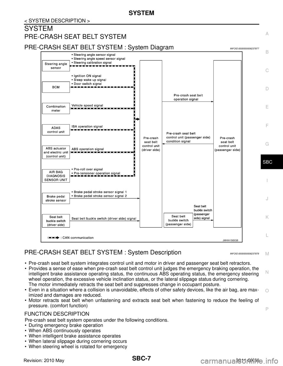
PRE-CRASH SEAT BELT SYSTEM : System DiagramINFOID:0000000006237877
PRE-CRASH SEAT BELT SYSTEM : System DescriptionINFOID:0000000006237878
Pre-crash seat belt system integrates control unit and motor in driver and passenger seat belt retractors.
Provides a sense of ease when pre-crash seat belt c ontrol unit judges the emergency braking operation, the
intelligent brake assistance operating status, the c ontinuous ABS operating status, the emergency steering
wheel operation, the excessive vehicle inclination stat us, or the lateral slippage status during cornering.
The motor immediately retracts the seat belt and suppresses change in occupant posture.
Even in a situation where a collision is unavoidable, effe cts of other safety devices, like the air bag, are max-
imized and damages are reduced.
Motor retracts seat belt when unfastening and extrac ts seat belt when fastening to reduce the feeling of
pressure. (comfort function)
FUNCTION DESCRIPTION
Pre-crash seat belt system operat es under the following conditions.
During emergency brake operation
When ABS continuously operates
When intelligent brake assistance operates
When lateral slippage during cornering occurs
When steering wheel is rotated for emergency
JMHIA1565GB
Revision: 2010 May2011 QX56
Page 4308 of 5598
DIAGNOSIS SYSTEM (PRE-CRASH SEAT BELT)SBC-11
< SYSTEM DESCRIPTION >
C
DE
F
G
I
J
K L
M A
B
SBC
N
O P
DIAGNOSIS SYSTEM (P RE-CRASH SEAT BELT)
CONSULT-III FunctionINFOID:0000000006237882
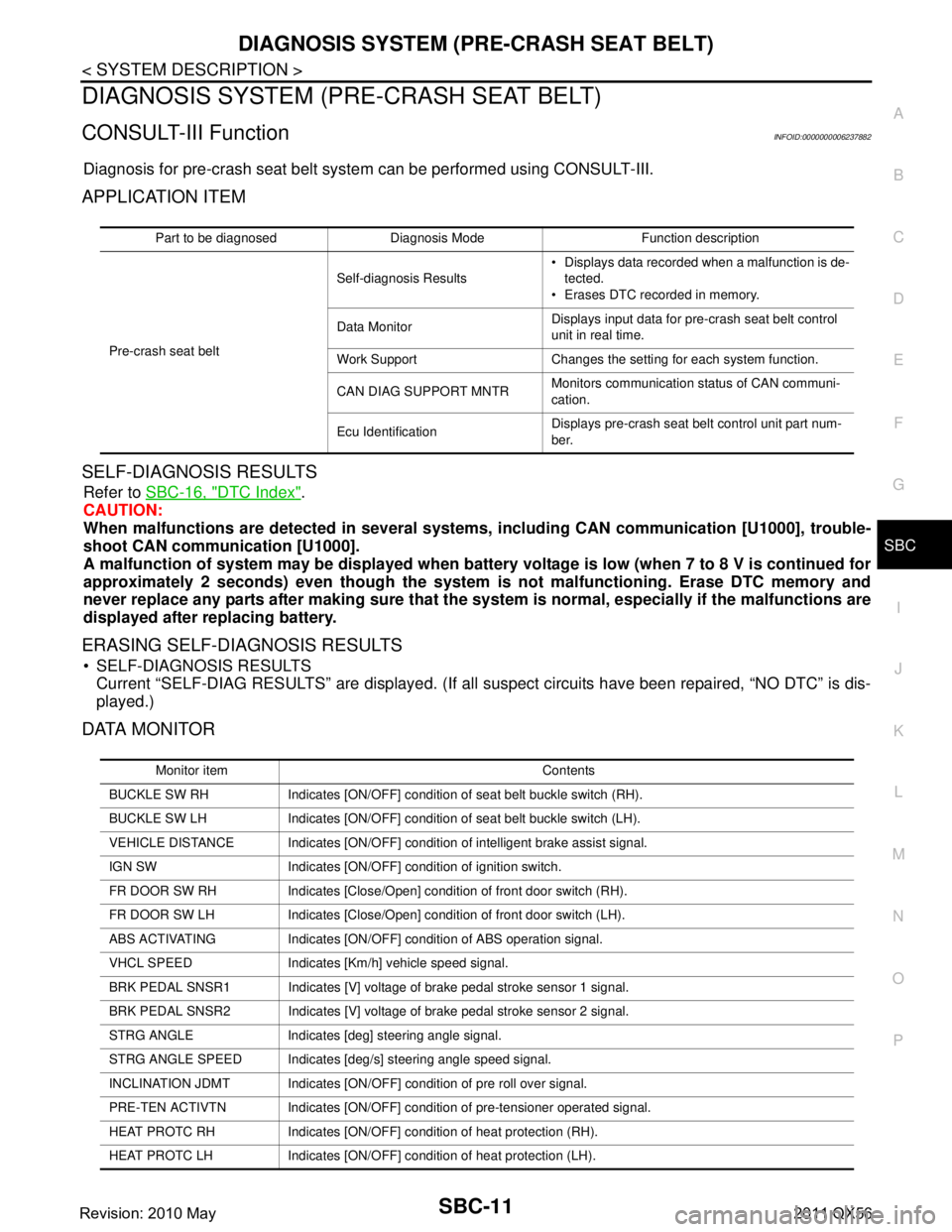
Diagnosis for pre-crash seat belt syst em can be performed using CONSULT-III.
APPLICATION ITEM
SELF-DIAGNOSIS RESULTS
Refer to SBC-16, "DTC Index".
CAUTION:
When malfunctions are detect ed in several systems, includin g CAN communication [U1000], trouble-
shoot CAN communication [U1000].
A malfunction of system may be disp layed when battery voltage is low (when 7 to 8 V is continued for
approximately 2 seconds) even though the system is not malfunctioning. Erase DTC memory and
never replace any parts after making sure that the syst em is normal, especially if the malfunctions are
displayed after replacing battery.
ERASING SELF-DIAGNOSIS RESULTS
SELF-DIAGNOSIS RESULTS Current “SELF-DIAG RESULTS” are displayed. (If all suspect circuits have been repaired, “NO DTC” is dis-
played.)
DATA MONITOR
Part to be diagnosed Diagnosis Mode Function description
Pre-crash seat belt Self-diagnosis Results
Displays data recorded when a malfunction is de-
tected.
Erases DTC recorded in memory.
Data Monitor Displays input data for pre-crash seat belt control
unit in real time.
Work Support Changes the setting for each system function.
CAN DIAG SUPPORT MNTR Monitors communication status of CAN communi-
cation.
Ecu Identification Displays pre-crash seat belt control unit part num-
ber.
Monitor item Contents
BUCKLE SW RH Indicates [ON/OFF] condition of seat belt buckle switch (RH).
BUCKLE SW LH Indicates [ON/OFF] condition of seat belt buckle switch (LH).
VEHICLE DISTANCE Indicates [ON/OFF] condit ion of intelligent brake assist signal.
IGN SW Indicates [ON/OFF] condition of ignition switch.
FR DOOR SW RH Indicates [Close/Open] condition of front door switch (RH).
FR DOOR SW LH Indicates [Close/Open] condition of front door switch (LH).
ABS ACTIVATING Indicates [ON/OFF] co ndition of ABS operation signal.
VHCL SPEED Indicates [Km/h] vehicle speed signal.
BRK PEDAL SNSR1 Indicates [V] voltage of brake pedal stroke sensor 1 signal.
BRK PEDAL SNSR2 Indicates [V] voltage of brake pedal stroke sensor 2 signal.
STRG ANGLE Indicates [deg] steering angle signal.
STRG ANGLE SPEED Indicates [deg/s] steering angle speed signal.
INCLINATION JDMT Indicates [ON/OFF] condition of pre roll over signal.
PRE-TEN ACTIVTN Indicates [ON/OFF] condition of pre-tensioner operated signal.
HEAT PROTC RH Indicates [ON/OFF] condition of heat protection (RH).
HEAT PROTC LH Indicates [ON/OFF] condition of heat protection (LH).
Revision: 2010 May2011 QX56
Page 4328 of 5598
DIAGNOSIS AND REPAIR WORKFLOWSBC-31
< BASIC INSPECTION >
C
DE
F
G
I
J
K L
M A
B
SBC
N
O P
BASIC INSPECTION
DIAGNOSIS AND REPAIR WORKFLOW
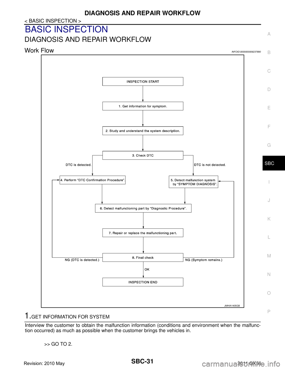
Work FlowINFOID:0000000006237890
1.GET INFORMATION FOR SYSTEM
Interview the customer to obtain the malfunction information (conditions and environment when the malfunc-
tion occurred) as much as possible when the customer brings the vehicles in.
>> GO TO 2.
JMHIA1405GB
Revision: 2010 May2011 QX56