length INFINITI QX56 2011 Factory Service Manual
[x] Cancel search | Manufacturer: INFINITI, Model Year: 2011, Model line: QX56, Model: INFINITI QX56 2011Pages: 5598, PDF Size: 94.53 MB
Page 261 of 5598

AV
CALIBRATING CAMERA IMAGE (AROUND VIEW MONITOR)
AV-113
< BASIC INSPECTION >
C
D E
F
G H
I
J
K L
M B A
O P
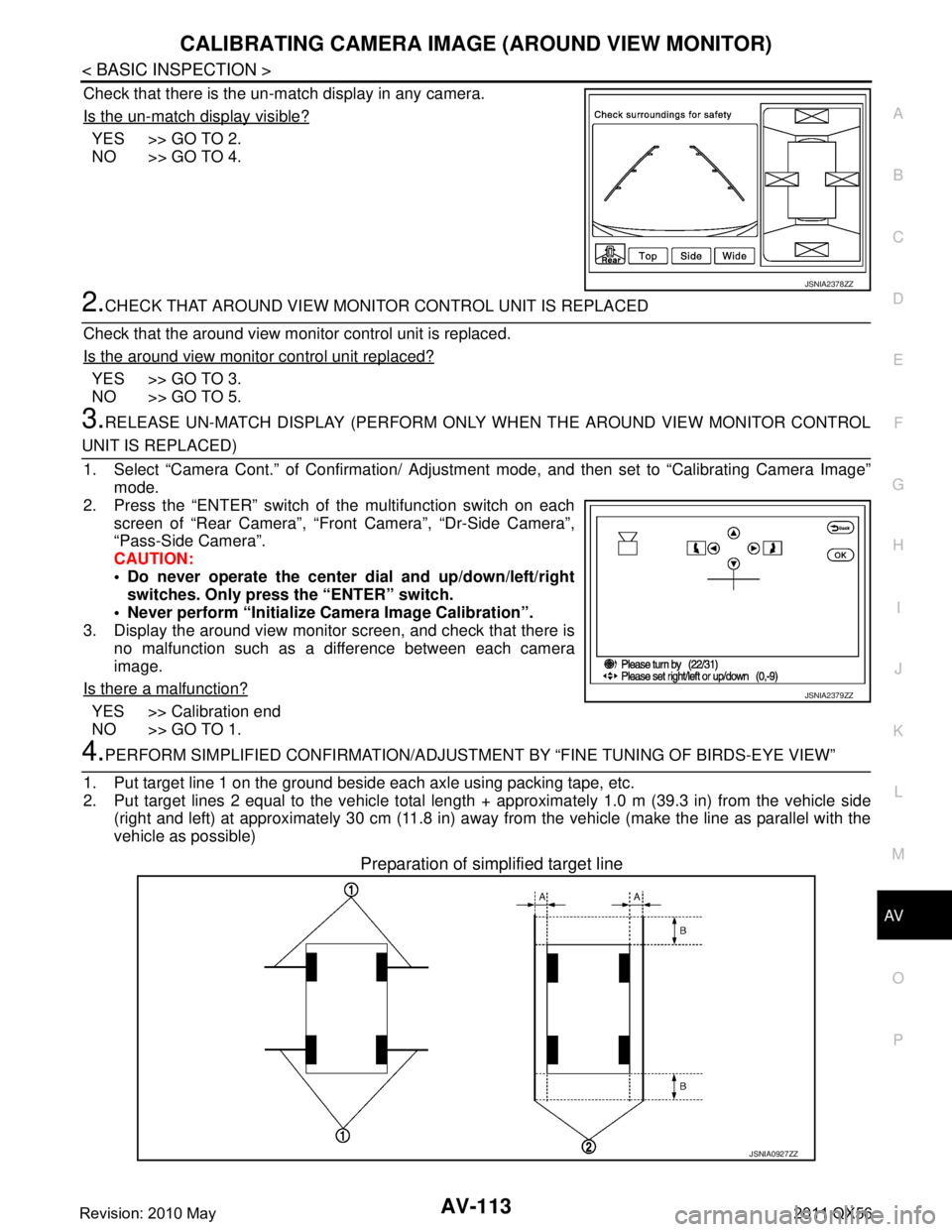
Check that there is the un-match display in any camera.
Is the un-match display visible?
YES >> GO TO 2.
NO >> GO TO 4.
2.CHECK THAT AROUND VIEW MONITOR CONTROL UNIT IS REPLACED
Check that the around view monitor control unit is replaced.
Is the around view monitor control unit replaced?
YES >> GO TO 3.
NO >> GO TO 5.
3.RELEASE UN-MATCH DISPLAY (PERFORM ONLY WHEN THE AROUND VIEW MONITOR CONTROL
UNIT IS REPLACED)
1. Select “Camera Cont.” of Confirmation/ Adjust ment mode, and then set to “Calibrating Camera Image”
mode.
2. Press the “ENTER” switch of the multifunction switch on each screen of “Rear Camera”, “Front Camera”, “Dr-Side Camera”\
,
“Pass-Side Camera”.
CAUTION:
Do never operate the center dial and up/down/left/right
switches. Only press the “ENTER” switch.
Never perform “Initialize Camera Image Calibration”.
3. Display the around view monitor screen, and check that there is
no malfunction such as a difference between each camera
image.
Is there a malfunction?
YES >> Calibration end
NO >> GO TO 1.
4.PERFORM SIMPLIFIED CONFIRMATION/ADJUSTM ENT BY “FINE TUNING OF BIRDS-EYE VIEW”
1. Put target line 1 on the ground beside each axle using packing tape, etc.
2. Put target lines 2 equal to the vehicle total length + approximately 1.0 m (39.3 in) from the vehicle side
(right and left) at approximately 30 cm (11.8 in) away from the vehicle (make the line as parallel with the
vehicle as possible)
Preparation of simplified target line
JSNIA2378ZZ
JSNIA2379ZZ
JSNIA0927ZZ
Revision: 2010 May2011 QX56
Page 491 of 5598

BRAKE PEDALBR-21
< REMOVAL AND INSTALLATION >
C
DE
G H
I
J
K L
M A
B
BR
N
O P
Install the brake pedal assembly and hydraulic booster assembly mounting nuts, and tighten it to the speci- fied torque. Refer to BR-28, "
Exploded View".
Perform adjustment after installation. Refer to BR-21, "
Inspection and Adjustment".
NOTE:
The clevis pin may be inserted in either direction.
Inspection and AdjustmentINFOID:0000000006222474
INSPECTION AFTER REMOVAL
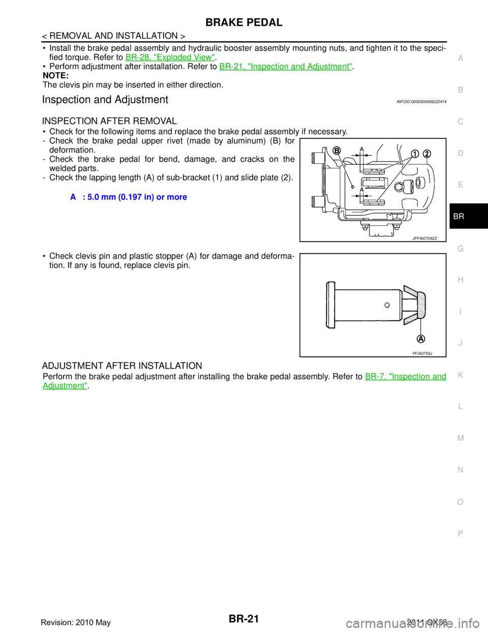
Check for the following items and replace the brake pedal assembly if necessary.
- Check the brake pedal upper rivet (made by aluminum) (B) for deformation.
- Check the brake pedal for bend, damage, and cracks on the welded parts.
- Check the lapping length (A) of sub-bracket (1) and slide plate (2).
Check clevis pin and plastic stopper (A) for damage and deforma-
tion. If any is found, replace clevis pin.
ADJUSTMENT AFTER INSTALLATION
Perform the brake pedal adjustment after installing the brake pedal assembly. Refer to BR-7, "Inspection and
Adjustment".
A : 5.0 mm (0.197 in) or more
JPFIA0724ZZ
PFIA0756J
Revision: 2010 May2011 QX56
Page 502 of 5598

BR-32
< REMOVAL AND INSTALLATION >
HYDRAULIC BOOSTER ASSEMBLY
Apply new brake fluid to grommet of between reservoir tank and grommet and ABS actuator and electric unit
(control unit).
Inspection and AdjustmentINFOID:0000000006222486
ADJUSTMENT BEFORE INSTALLATION
Input Rod Length adjustment
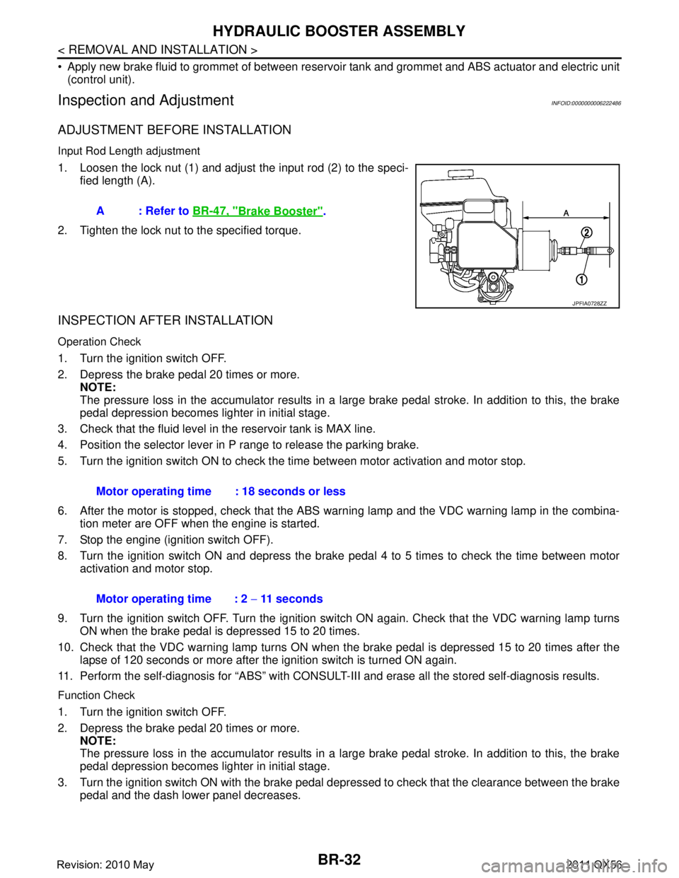
1. Loosen the lock nut (1) and adjust the input rod (2) to the speci-
fied length (A).
2. Tighten the lock nut to the specified torque.
INSPECTION AFTER INSTALLATION
Operation Check
1. Turn the ignition switch OFF.
2. Depress the brake pedal 20 times or more. NOTE:
The pressure loss in the accumulator results in a large brake pedal stroke. In addition to this, the brake
pedal depression becomes lighter in initial stage.
3. Check that the fluid level in the reservoir tank is MAX line.
4. Position the selector lever in P range to release the parking brake.
5. Turn the ignition switch ON to check the time between motor activation and motor stop.
6. After the motor is stopped, check that the ABS warn ing lamp and the VDC warning lamp in the combina-
tion meter are OFF when the engine is started.
7. Stop the engine (ignition switch OFF).
8. Turn the ignition switch ON and depress the brake pedal 4 to 5 times to check the time between motor activation and motor stop.
9. Turn the ignition switch OFF. Turn the ignition swit ch ON again. Check that the VDC warning lamp turns
ON when the brake pedal is depressed 15 to 20 times.
10. Check that the VDC warning lamp turns ON when the brake pedal is depressed 15 to 20 times after the lapse of 120 seconds or more after the ignition switch is turned ON again.
11. Perform the self-diagnosis for “ABS” with CONSULT- III and erase all the stored self-diagnosis results.
Function Check
1. Turn the ignition switch OFF.
2. Depress the brake pedal 20 times or more.
NOTE:
The pressure loss in the accumulator results in a large brake pedal stroke. In addition to this, the brake
pedal depression becomes lighter in initial stage.
3. Turn the ignition switch ON with the brake pedal depr essed to check that the clearance between the brake
pedal and the dash lower panel decreases. A : Refer to
BR-47, "
Brake Booster".
JPFIA0728ZZ
Motor operating time : 18 seconds or less
Motor operating time : 2 − 11 seconds
Revision: 2010 May2011 QX56
Page 517 of 5598

SERVICE DATA AND SPECIFICATIONS (SDS)
BR-47
< SERVICE DATA AND SPECIFICATIONS (SDS)
C
D E
G H
I
J
K L
M A
B
BR
N
O P
SERVICE DATA AND SPECIFICATIONS (SDS)
SERVICE DATA AND SPECIFICATIONS (SDS)
General SpecificationINFOID:0000000006222502
Unit: mm (in)
Brake PedalINFOID:0000000006222503
Unit: mm (in)
Brake BoosterINFOID:0000000006222504
Unit: mm (in)
Front Disc BrakeINFOID:0000000006222505
Unit: mm (in)
Rear Disc BrakeINFOID:0000000006222506
Unit: mm (in)
Front brake Cylinder bore diameter 50.8 (2.000)
× 2
Pad length × width × thickness 151.6 (5.97) × 56.5 (2.224) × 12.0 (0.472)
Rotor outer diameter × thickness 350 (13.78) × 30.0 (1.181)
Rear brake Cylinder bore diameter 48.1 (10894)
Pad length
× width × thickness 110.0 (4.43) × 41.0 (1.614) × 9.0 (0.354)
Rotor outer diameter × thickness 350 (13.78) × 20.0 (0.787)
Control valve Valve type Electric brake force distribution
Recommended brake fluid Refer to MA-10, "
Fluids and Lubricants".
Item Standard
Brake pedal height 168.5 (6.63) – 178.5 (7.03)
Depressed brake pedal height
[Depressing 490 N (50 kg, 110 lb) while turning the engine ON] 100 (3.94) or more
Clearance between stop lamp switch and brake switch threaded end and the
brake pedal bracket 0.2 (0.008) – 1.96 (0.0772)
Brake pedal play 3 (0.12) – 11 (0.43)
Item Standard
Input rod length 202.2 (7.96)
Item Limit
Brake pad Wear thickness 1.5 (0.059)
Disc rotor Wear thickness 28.5 (1.122)
Thickness variation (measured at 8 positions) 0.015 (0.0006)
Runout (with it attached to the vehicle) 0.053 (0.0021)
Item Limit
Brake pad Wear thickness 2.0 (0.079)
Disc rotor Wear thickness 18.0 (0.709)
Thickness variation (measured at 8 positions) 0.015 (0.0006)
Runout (with it attached to the vehicle) 0.05 (0.0020)
Revision: 2010 May2011 QX56
Page 723 of 5598

BRM-48
< SERVICE DATA AND SPECIFICATIONS (SDS)
BODY ALIGNMENT
SERVICE DATA AND SPECIFICATIONS (SDS)
BODY ALIGNMENT
Body Center MarksINFOID:0000000006248507
A mark is placed on each part of the body to indicate the vehicle center. When repairing the vehicle frame
(members, pillars, etc.) damaged by an accident which it enables more accurate and effective repair by using
these marks together with body alignment specifications.
Unit: mm (in)
DescriptionINFOID:0000000006248508
All dimensions indicated in the figures are actual.
When using a tracking gauge, adjust both pointers to equal length. Then check the pointers and gauge itself
to make sure there is no free play.
: Vehicle front
Points Portion Marks
A Upper dash Hole 7 ×12 (0.28 ×0.47)
B Cowl top Embossment
C Rear roof Indent
JSKIA1895ZZ
Revision: 2010 May2011 QX56
Page 1935 of 5598
![INFINITI QX56 2011 Factory Service Manual
SERVICE DATA AND SPECIFICATIONS (SDS)
DLN-133
< SERVICE DATA AND SPECIFICATIONS (SDS) [FRONT PROPELLER SHAFT: 2F P15]
C
EF
G H
I
J
K L
M A
B
DLN
N
O P
SERVICE DATA AND SPECIFICATIONS (SDS)
SERVICE D INFINITI QX56 2011 Factory Service Manual
SERVICE DATA AND SPECIFICATIONS (SDS)
DLN-133
< SERVICE DATA AND SPECIFICATIONS (SDS) [FRONT PROPELLER SHAFT: 2F P15]
C
EF
G H
I
J
K L
M A
B
DLN
N
O P
SERVICE DATA AND SPECIFICATIONS (SDS)
SERVICE D](/img/42/57033/w960_57033-1934.png)
SERVICE DATA AND SPECIFICATIONS (SDS)
DLN-133
< SERVICE DATA AND SPECIFICATIONS (SDS) [FRONT PROPELLER SHAFT: 2F P15]
C
EF
G H
I
J
K L
M A
B
DLN
N
O P
SERVICE DATA AND SPECIFICATIONS (SDS)
SERVICE DATA AND SPECIFICATIONS (SDS)
General SpecificationINFOID:0000000006222360
Propeller Shaft RunoutINFOID:0000000006222361
Unit: mm (in)
Journal Axial PlayINFOID:0000000006222362
Unit: mm (in)
Applied model 4WD
VK56VD A/T
Propeller shaft model 2F P15
Number of joints 2
Type of journal bearings 1st joint Shell type
2rd joint Shell type
Coupling method with transfer Flange type
Coupling method with rear final drive Flange type
Shaft length (Spider to spider) 729 mm (28.70 in)
Shaft outer diameter 68.9 mm (2.713 in)
Item Limit
Propeller shaft runout 1.0 (0.04)
Item Standard
Journal axial play 0.06 (0.0024)
Revision: 2010 May2011 QX56
Page 1942 of 5598
![INFINITI QX56 2011 Factory Service Manual
DLN-140
< SERVICE DATA AND SPECIFICATIONS (SDS) [REAR PROPELLER SHAFT: 2F P26]
SERVICE DATA AND SPECIFICATIONS (SDS)
SERVICE DATA AND SPECIFICATIONS (SDS)
SERVICE DATA AND SPECIFICATIONS (SDS)
Genera INFINITI QX56 2011 Factory Service Manual
DLN-140
< SERVICE DATA AND SPECIFICATIONS (SDS) [REAR PROPELLER SHAFT: 2F P26]
SERVICE DATA AND SPECIFICATIONS (SDS)
SERVICE DATA AND SPECIFICATIONS (SDS)
SERVICE DATA AND SPECIFICATIONS (SDS)
Genera](/img/42/57033/w960_57033-1941.png)
DLN-140
< SERVICE DATA AND SPECIFICATIONS (SDS) [REAR PROPELLER SHAFT: 2F P26]
SERVICE DATA AND SPECIFICATIONS (SDS)
SERVICE DATA AND SPECIFICATIONS (SDS)
SERVICE DATA AND SPECIFICATIONS (SDS)
General SpecificationINFOID:0000000006222369
Propeller Shaft RunoutINFOID:0000000006222370
Unit: mm (in)
Journal Axial PlayINFOID:0000000006222371
Unit: mm (in)
Applied model 4WD
VK56VD A/T
Propeller shaft model 2F P26
Number of joints 2
Type of journal bearings 1st joint Shell type
2rd joint Shell type
Coupling method with transfer Flange type
Coupling method with rear final drive Flange type
Shaft length (Spider to spider) 1168mm (45.98 in)
Shaft outer diameter 101.6 mm (4.00 in)
Item Limit
Propeller shaft runout 1.0 (0.04)
Item Standard
Journal axial play 0 (0)
Revision: 2010 May2011 QX56
Page 1949 of 5598
![INFINITI QX56 2011 Factory Service Manual
SERVICE DATA AND SPECIFICATIONS (SDS)
DLN-147
< SERVICE DATA AND SPECIFICATIONS (SDS) [REAR PROPELLER SHAFT: 2S1410]
C
EF
G H
I
J
K L
M A
B
DLN
N
O P
SERVICE DATA AND SPECIFICATIONS (SDS)
SERVICE DA INFINITI QX56 2011 Factory Service Manual
SERVICE DATA AND SPECIFICATIONS (SDS)
DLN-147
< SERVICE DATA AND SPECIFICATIONS (SDS) [REAR PROPELLER SHAFT: 2S1410]
C
EF
G H
I
J
K L
M A
B
DLN
N
O P
SERVICE DATA AND SPECIFICATIONS (SDS)
SERVICE DA](/img/42/57033/w960_57033-1948.png)
SERVICE DATA AND SPECIFICATIONS (SDS)
DLN-147
< SERVICE DATA AND SPECIFICATIONS (SDS) [REAR PROPELLER SHAFT: 2S1410]
C
EF
G H
I
J
K L
M A
B
DLN
N
O P
SERVICE DATA AND SPECIFICATIONS (SDS)
SERVICE DATA AND SPECIFICATIONS (SDS)
General SpecificationINFOID:0000000006222442
Propeller Shaft RunoutINFOID:0000000006222443
Unit: mm (in)
Journal Axial PlayINFOID:0000000006222444
Unit: mm (in)
Applied model 2WD
VK56VD A/T
Propeller shaft model 2S1410
Number of joints 2
Type of journal bearings 1st joint Shell type
2rd joint Shell type
Coupling method with transfer Sleeve type
Coupling method with rear final drive Flange type
Shaft length (Spider to spider) 1590.4 mm (62.61 in)
Shaft outer diameter 127.6 mm (5.02 in)
Item Limit
Propeller shaft runout 1.02 (0.0402)
Item Standard
Journal axial play 0.02 (0.0008)
Revision: 2010 May2011 QX56
Page 2061 of 5598
![INFINITI QX56 2011 Factory Service Manual
SYSTEMEC-37
< SYSTEM DESCRIPTION > [VK56VD]
C
D
E
F
G H
I
J
K L
M A
EC
NP
O
*1: This sensor is not used to control the engine system under normal conditions.
*2: ECM determines the start signal statu INFINITI QX56 2011 Factory Service Manual
SYSTEMEC-37
< SYSTEM DESCRIPTION > [VK56VD]
C
D
E
F
G H
I
J
K L
M A
EC
NP
O
*1: This sensor is not used to control the engine system under normal conditions.
*2: ECM determines the start signal statu](/img/42/57033/w960_57033-2060.png)
SYSTEMEC-37
< SYSTEM DESCRIPTION > [VK56VD]
C
D
E
F
G H
I
J
K L
M A
EC
NP
O
*1: This sensor is not used to control the engine system under normal conditions.
*2: ECM determines the start signal status by the signals of engine speed and battery voltage.
SYSTEM DESCRIPTION
The adoption of the direct fuel injection method enables
more accurate adjustment of fuel injection quantity by
injecting atomized high-pressure fuel directly into the cylinder. This method allows high-powered engine, low
fuel consumption, and emissions-reduction.
The amount of fuel injected from the fuel injector is determined by the ECM. The ECM controls the length of
time the valve remains open (injection pulse duration). T he amount of fuel injected is a program value in the
ECM memory. The program value is preset by engi ne operating conditions. These conditions are determined
by input signals (for engine speed and intake air and fuel rail pressure) from the crankshaft position sensor,
camshaft position sensor, mass air flow sensor and the fuel rail pressure sensor.
VARIOUS FUEL INJECTION INCREASE/DECREASE COMPENSATION
In addition, the amount of fuel injected is compens ated to improve engine performance under various operat-
ing conditions as listed below.
When starting the engine
During acceleration
Hot-engine operation
When selector lever position is changed from N to D
High-load, high-speed operation
During deceleration
During high engine speed operation
FUEL INJECTION CONTROL
Stratified-charge Combustion
Stratified-charge combustion is a combustion method wh ich enables extremely lean combustion by injecting
fuel in the latter half of a compression process, coll ecting combustible air-fuel around the spark plug, and form-
ing fuel-free airspace around the mixture.
Right after a start with the engine cold, the catalyst warm-up is accelerated by stratified-charge combustion.
Homogeneous Combustion
Sensor Input signal to ECM ECM function Actuator
Crankshaft position sensor Engine speed*
2
Fuel injection
& mixture ratio
controlFuel injector
Camshaft position sensor Camshaft position
Mass air flow sensor Amount of intake air
Intake air temperature sensor Intake air temperature
Engine coolant temperature sensor Engine coolant temperature
Air fuel ratio (A/F) sensor 1 Density of oxygen in exhaust gas
Fuel rail pressure sensor Fuel rail pressure
Throttle position sensor Throttle position
Accelerator pedal position sensor Accelerator pedal position
TCM Gear position
Battery
Battery voltage*
2
Knock sensor Engine knocking condition
Power steering pressure sensor Power steering operation
Heated oxygen sensor 2*
1Density of oxygen in exhaust gas
ABS actuator and electric unit (control unit) VDC/TCS operation command
A/C auto amp. A/C ON signal
Combination meter Vehicle speed
Revision: 2010 May2011 QX56
Page 2086 of 5598
![INFINITI QX56 2011 Factory Service Manual
EC-62
< SYSTEM DESCRIPTION >[VK56VD]
DIAGNOSIS SYSTEM (ECM)
NOTE:
Wait until the same DTC (or 1st trip DTC)
appears to completely confirm all DTCs.
How to Read Self-diagnostic Results
The DTC and 1s INFINITI QX56 2011 Factory Service Manual
EC-62
< SYSTEM DESCRIPTION >[VK56VD]
DIAGNOSIS SYSTEM (ECM)
NOTE:
Wait until the same DTC (or 1st trip DTC)
appears to completely confirm all DTCs.
How to Read Self-diagnostic Results
The DTC and 1s](/img/42/57033/w960_57033-2085.png)
EC-62
< SYSTEM DESCRIPTION >[VK56VD]
DIAGNOSIS SYSTEM (ECM)
NOTE:
Wait until the same DTC (or 1st trip DTC)
appears to completely confirm all DTCs.
How to Read Self-diagnostic Results
The DTC and 1st trip DTC are indicated by the number of blinks of the MIL as shown below.
The DTC and 1st trip DTC are displayed at the same time. If the MIL does not illuminate in diagnostic test
mode I (Malfunction warning), all displayed items are 1s t trip DTCs. If only one code is displayed when the MIL
illuminates in “malfunction warning” mode, it is a DTC; if two or more codes are displayed, they may be either
DTCs or 1st trip DTCs. DTC No. is same as that of 1st trip DTC. These unidentified codes can be identified by
using the CONSULT-III or GST. A DTC will be used as an example for how to read a code.
A particular trouble code can be identified by the number of four-digit numeral flashes per the following.
The length of time the 1,000th-digit numeral flashes on and off is 1.2 seconds consisting of an ON (0.6-sec-
onds) - OFF (0.6-seconds) cycle.
The 100th-digit numeral and lower digit numerals consis t of a 0.3-seconds ON and 0.3-seconds OFF cycle.
A change from one digit numeral to another occurs at an inte rval of 1.0-second OFF. In other words, the later
numeral appears on the display 1.3 seconds after the former numeral has disappeared.
A change from one trouble code to another occurs at an interval of 1.8-seconds OFF.
PBIB0092E
PBIB3005E
Number 0123456789ABCDEF
Flashes 10123456789111213141516
Revision: 2010 May2011 QX56