fuse chart INFINITI QX56 2011 Factory Service Manual
[x] Cancel search | Manufacturer: INFINITI, Model Year: 2011, Model line: QX56, Model: INFINITI QX56 2011Pages: 5598, PDF Size: 94.53 MB
Page 3404 of 5598

IP-14
< REMOVAL AND INSTALLATION >
INSTRUMENT PANEL ASSEMBLY
Removal and Installation
INFOID:0000000006113098
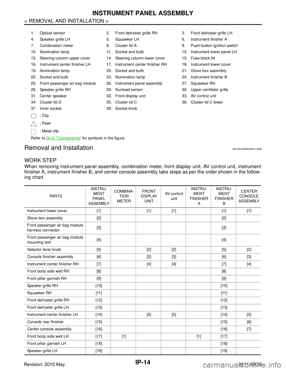
WORK STEP
When removing instrument panel assembly, combination meter, front display unit, AV control unit, instrument
finisher A, instrument fini sher B, and center console assembly take st eps as per the order shown in the follow-
ing chart.
1. Optical sensor 2. Front defroster grille RH 3. Front defroster grille LH
4. Speaker grille LH 5. Squawker LH 6. Instrument finisher A
7. Combination meter 8. Cluster lid A 9. Push-button ignition switch
10. Illumination lamp 11. Socket and bulb 12. Instrument lower panel LH
13. Steering column upper cover 14. Steering column lower cover 15. Fuse block lid
16. Instrument center finisher LH 17. Instrument center finisher RH 18. Instrument lower cover
19. Illumination lamp 20. Socket and bulb 21. Glove box assembly
22. Socket and bulb 23. Illumination lamp 24. Instrument finisher B
25. Front passenger air bag module 26. Instrument panel assembly 27. Squawker RH
28. Speaker grille RH 29. Sunload sensor 30. Upper ventilator grille
31. Center speaker 32. Front display unit 33. AV control unit
34. Cluster lid D 35. Cluster lid C 36. Cluster lid C lower
37. Inner socket 38. Socket knob
: Clip
: Pawl
: Metal clip
Refer to GI-4, "
Components" for symbols in the figure.
PA R T S INSTRU-
MENT
PA N E L
ASSEMBLY COMBINA-
TION
METER FRONT
DISPLAY
UNIT AV c o n t r o l
unit INSTRU-
MENT
FINISHER A INSTRU-
MENT
FINISHER B CENTER
CONSOLE
ASSEMBLY
Instrument lower cover [1] [1] [1] [1] [1]
Glove box assembly [2] [2]
Front passenger air bag module
harness connector [3] [3]
Front passenger air bag module
mounting bolt [4] [4]
Selector lever knob [5] [2] [2] [5] [2]
Console finisher assembly [6] [3] [3] [6] [3]
Instrument center finisher RH [7] [4] [4] [7] [4]
Front body side welt RH [8] [8]
Front pillar garnish RH [9] [9]
Speaker grille RH [10] [10]
Squawker RH [11] [11]
Front defroster grille RH [12] [12]
Front defroster grille LH [13] [13]
Instrument center finisher LH [14] [5] [5] [14] [5]
Console rear finisher [15] [15] [6]
Center console assembly [16] [16] [7]
Front body side welt LH [17] [1] [1] [17]
Front pillar garnish LH [18] [18]
Speaker grille LH [19] [19]
Revision: 2010 May2011 QX56
Page 5144 of 5598
![INFINITI QX56 2011 Factory Service Manual
TM-56
< SYSTEM DESCRIPTION >[7AT: RE7R01B]
SYSTEM
Input/Output Signal Chart
*: This signal is transmitted via CAN communication line.
The TCM receives the manual mode signal, non-manual mode signal INFINITI QX56 2011 Factory Service Manual
TM-56
< SYSTEM DESCRIPTION >[7AT: RE7R01B]
SYSTEM
Input/Output Signal Chart
*: This signal is transmitted via CAN communication line.
The TCM receives the manual mode signal, non-manual mode signal](/img/42/57033/w960_57033-5143.png)
TM-56
< SYSTEM DESCRIPTION >[7AT: RE7R01B]
SYSTEM
Input/Output Signal Chart
*: This signal is transmitted via CAN communication line.
The TCM receives the manual mode signal, non-manual mode signal, manual mode shift up signal and
manual mode shift down signal from combination meter via CAN communication line. The TCM shifts shift
pattern control to the manual mode based on these signal s, and then shifts the A/T by operating each sole-
noid valve according to the shift operation of the driver.
The TCM prohibits the manual mode while being in fail-safe mode due to an A/T malfunction, etc. Refer to TM-74, "
Fail-Safe".
Manual Mode Information
The TCM transmits the manual mode shift refusal signal to the combination meter if the TCM refuses the
transmission from the driving status of vehicle when the selector lever shifts to “UP (+ side)” or “DOWN (−
side)” side. The combination meter blinks shift indicator on the combination meter and sounds the buzzer to
indicate the driver that the shifting is not performed when receiving this signal. However, the TCM does not
transmit the manual mode shift refusal signal in the conditions as per the following.
- When the selector lever shifts to “DOWN ( − side)” side in 1GR.
- When the selector lever shifts to “UP (+ side)” side in 7GR.
LOCK-UP CONTROL
LOCK-UP CONTROL : System DiagramINFOID:0000000006226777
LOCK-UP CONTROL : System DescriptionINFOID:0000000006226778
The torque converter clutch piston in the torque conv erter is engaged to eliminate torque converter slip to
increase power transmission efficiency.
Lock-up operation, however, is prohibited when A/T fluid temperature is too low.
The torque converter clutch control valve operation is controlled by the torque converter clutch solenoid
valve, which is controlled by a signal from TCM, and the torque converter clutch control valve engages or
releases the torque converter clutch piston.
Item Signal TCM function Actuator
Output speed sensor Vehicle speed
Manual mode High and low reverse clutch
solenoid valve
Direct clutch solenoid valve
Input clutch solenoid valve
Low brake solenoid valve
2346 brake solenoid valve
Front brake solenoid valve
Torque converter clutch sole- noid valve
Line pressure solenoid valve
Anti-interlock solenoid valve
A/T fluid temperature sensor ATF temperature
ECM
Engine speed signal*
Accelerator pedal position sig-
nal*
Combination meter Manual mode signal*
Non-manual mode signal*
Manual mode shift up signal*
Manual mode shift down signal*
JSDIA1350GB
Revision: 2010 May2011 QX56