ignition INFINITI QX56 2011 Factory Service Manual
[x] Cancel search | Manufacturer: INFINITI, Model Year: 2011, Model line: QX56, Model: INFINITI QX56 2011Pages: 5598, PDF Size: 94.53 MB
Page 3 of 5598

QUICK REFERENCE CHART QX56
QUICK REFERENCE CHART QX56PFP:00000
ENGINE TUNE-UP DATA (VK56VD)ELS0003W
Engine modelVK56VD
Firing order 1-8-7-3-6-5-4-2
Idle speed
A/T (In “P or N” position) rpm
600 ± 50
Ignition timing
(BTDC at idle speed) 12
° ± 2 °
CO% at idle 0.7 - 9.9 % and engine runs smoothly
Tensions of drive belt Auto adjustment by auto tensioner
Radiater cap relief pressure kPa (kg/cm
2 , psi)
Standard 108.2 - 127.8 (1.1 - 1.3, 15.7 - 18.5)
Limit 98 (1.0, 14)
Cooling system leakage testing pressure kPa (kg/cm
2 , psi)186 (1.9, 27)
Compression pressure kPa (kg/cm
2 , psi)/rpm
Standard 1,667 (17, 242)/200
Minimum 1,226 (12.5, 178)/200
Differential limit between cylinders 98 (1.0, 14)/200
Spark plug
(Iridium-tipped type) Make NGK
Standard type DILKAR7B11
Gap (Standard) mm (in) 1.1 (0.043)
2011
Page 7 of 5598
ACC-2
< PRECAUTION >
PRECAUTIONS
PRECAUTION
PRECAUTIONS
Precaution for Supplemental Restraint System (SRS) "AIR BAG" and "SEAT BELT
PRE-TENSIONER"
INFOID:0000000006289699
The Supplemental Restraint System such as “A IR BAG” and “SEAT BELT PRE-TENSIONER”, used along
with a front seat belt, helps to reduce the risk or severi ty of injury to the driver and front passenger for certain
types of collision. This system includes seat belt switch inputs and dual stage front air bag modules. The SRS
system uses the seat belt switches to determine the front air bag deployment, and may only deploy one front
air bag, depending on the severity of a collision and w hether the front occupants are belted or unbelted.
Information necessary to service the system safely is included in the “SRS AIR BAG” and “SEAT BELT” of this
Service Manual.
WARNING:
• To avoid rendering the SRS inopera tive, which could increase the risk of personal injury or death in
the event of a collision that would result in air bag inflation, all maintenance must be performed by
an authorized NISS AN/INFINITI dealer.
Improper maintenance, including in correct removal and installation of the SRS, can lead to personal
injury caused by unintent ional activation of the system. For re moval of Spiral Cable and Air Bag
Module, see the “SRS AIR BAG”.
Do not use electrical test equipmen t on any circuit related to the SRS unless instructed to in this
Service Manual. SRS wiring harnesses can be identi fied by yellow and/or orange harnesses or har-
ness connectors.
PRECAUTIONS WHEN USING POWER TOOLS (AIR OR ELECTRIC) AND HAMMERS
WARNING:
When working near the Air Bag Diagnosis Sensor Unit or other Air Bag System sensors with the ignition ON or engine running, DO NOT use air or electric power tools or strike near the sensor(s)
with a hammer. Heavy vibration could activate the sensor(s) and deploy the air bag(s), possibly
causing serious injury.
When using air or electric power tools or hammers , always switch the ignition OFF, disconnect the
battery, and wait at least 3 minu tes before performing any service.
Revision: 2010 May2011 QX56
Page 14 of 5598
PRECAUTIONSADP-5
< PRECAUTION >
C
DE
F
G H
I
K L
M A
B
ADP
N
O P
PRECAUTION
PRECAUTIONS
Precaution for Supplemental Restraint System (SRS) "AIR BAG" and "SEAT BELT
PRE-TENSIONER"
INFOID:0000000006248300
The Supplemental Restraint System such as “A IR BAG” and “SEAT BELT PRE-TENSIONER”, used along
with a front seat belt, helps to reduce the risk or severi ty of injury to the driver and front passenger for certain
types of collision. This system includes seat belt switch inputs and dual stage front air bag modules. The SRS
system uses the seat belt switches to determine the front air bag deployment, and may only deploy one front
air bag, depending on the severity of a collision and whether the front occupants are belted or unbelted.
Information necessary to service the system safely is included in the “SRS AIR BAG” and “SEAT BELT” of this
Service Manual.
WARNING:
• To avoid rendering the SRS inoper ative, which could increase the risk of personal injury or death in
the event of a collision that would result in air ba g inflation, all maintenance must be performed by
an authorized NISSAN/INFINITI dealer.
Improper maintenance, including in correct removal and installation of the SRS, can lead to personal
injury caused by unintentional act ivation of the system. For removal of Spiral Cable and Air Bag
Module, see the “SRS AIR BAG”.
Do not use electrical test equipm ent on any circuit related to the SRS unless instructed to in this
Service Manual. SRS wiring harnesses can be identi fied by yellow and/or orange harnesses or har-
ness connectors.
PRECAUTIONS WHEN USING POWER TOOLS (AIR OR ELECTRIC) AND HAMMERS
WARNING:
When working near the Air Bag Diagnosis Sensor Unit or other Air Bag System sensors with the
ignition ON or engine running, DO NOT use air or electric power tools or strike near the sensor(s)
with a hammer. Heavy vibration could activate the sensor(s) and deploy the air bag(s), possibly
causing serious injury.
When using air or electric power tools or hammers , always switch the ignition OFF, disconnect the
battery, and wait at least 3 minutes before performing any service.
Revision: 2010 May2011 QX56
Page 16 of 5598
COMPONENT PARTSADP-7
< SYSTEM DESCRIPTION >
C
DE
F
G H
I
K L
M A
B
ADP
N
O P
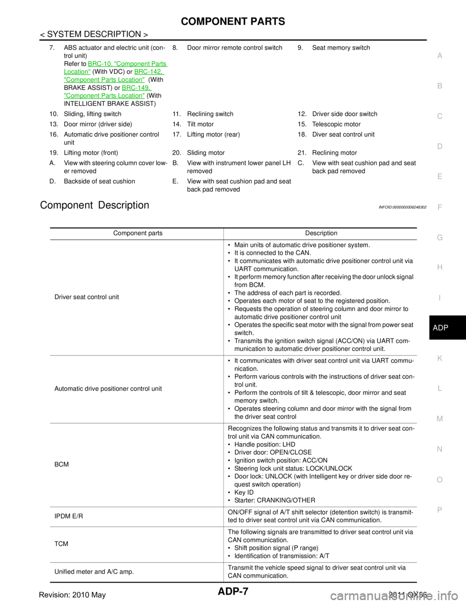
Component DescriptionINFOID:0000000006248302
7. ABS actuator and electric unit (con- trol unit)
Refer to BRC-10, "
Component Parts
Location" (With VDC) or BRC-142,
"Component Parts Location" (With
BRAKE ASSIST) or BRC-149,
"Component Parts Location" (With
INTELLIGENT BRAKE ASSIST) 8. Door mirror remote
control switch 9. Seat memory switch
10. Sliding, lifting switch 11. Reclining switch 12. Driver side door switch
13. Door mirror (driver side) 14. T ilt motor 15. Telescopic motor
16. Automatic drive positioner control unit 17. Lifting motor (rear) 18.
Diver seat control unit
19. Lifting motor (front) 20. Sliding motor 21. Reclining motor
A. View with steering column cover low- er removed B. View with instrument lower panel LH
removed C. View with seat cushion pad and seat
back pad removed
D. Backside of seat cushion E. View with seat cushion pad and seat back pad removed
Component parts Description
Driver seat control unit Main units of automatic drive positioner system.
It is connected to the CAN.
It communicates with automatic drive positioner control unit via
UART communication.
It perform memory function after receiving the door unlock signal
from BCM.
The address of each part is recorded.
Operates each motor of seat to the registered position.
Requests the operation of steering column and door mirror to automatic drive positioner control unit
Operates the specific seat motor with the signal from power seat
switch.
Transmits the ignition switch signal (ACC/ON) via UART com- munication to automatic driver positioner control unit.
Automatic drive positioner control unit It communicates with driver seat control unit via UART commu-
nication.
Perform various controls with the instructions of driver seat con- trol unit.
Perform the controls of tilt & telescopic, door mirror and seat memory switch.
Operates steering column and door mirror with the signal from the driver seat control
BCM Recognizes the following status and transmits it to driver seat con-
trol unit via CAN communication.
Handle position: LHD
Driver door: OPEN/CLOSE
Ignition switch position: ACC/ON
Steering lock unit status: LOCK/UNLOCK
Door lock: UNLOCK (with Intelligent key or driver side door re-
quest switch operation)
Key ID
Starter: CRANKING/OTHER
IPDM E/R ON/OFF signal of A/T shift selector (detention switch) is transmit-
ted to driver seat control unit via CAN communication.
TCM The following signals are transmitted to driver seat control unit via
CAN communication.
Shift position signal (P range)
Identification of transmission: A/T
Unified meter and A/C amp. Transmit the vehicle speed signal to driver seat control unit via
CAN communication.
Revision: 2010 May2011 QX56
Page 21 of 5598

ADP-12
< SYSTEM DESCRIPTION >
SYSTEM
NOTE:
The lumbar support system are controlled independently with no link to the automatic drive positioner system.
Refer to SE-16, "
LUMBAR SUPPORT SYSTEM : System Description".
Sleep control
Driver seat control unit equips sleep control for reducing power consumption.
The system switches to sleep control when al l of the following conditions are satisfied.
Ignition switch is OFF (steering lock status).
All devices of auto driving pos ition system are not operating.
45 seconds timer of driver s eat control unit is not operating.
Set switch and memory switch (1 and 2) are OFF.
Wake-up control
Sleep control releases when detecting status change in either of the following item.
CAN communication
Power seat switch
Set switch and seat memory switch (1 and 2)
Tilt & telescopic switch
MANUAL FUNCTION
Function Description
Manual function The driving position (seat, steering column and door mirror position) can be adjusted
by using the power seat switch, tilt & telescopic switch or door mirror remote control
switch.
Memory function The seat, steering column and door mirror move to the stored driving position by
pressing seat memory switch (1 or 2).
Entry/Exit assist function Exit On exit, the seat moves backward and the steering column moves upward.
Entry
On entry, the seat and steering column returns from exiting position to the previous
driving position.
Intelligent Key interlock function Perform memory operation, exiting operation and entry operation by Intelligent Key
unlock operation or driver side door request switch unlock operation.
Revision: 2010 May2011 QX56
Page 22 of 5598
SYSTEMADP-13
< SYSTEM DESCRIPTION >
C
DE
F
G H
I
K L
M A
B
ADP
N
O P
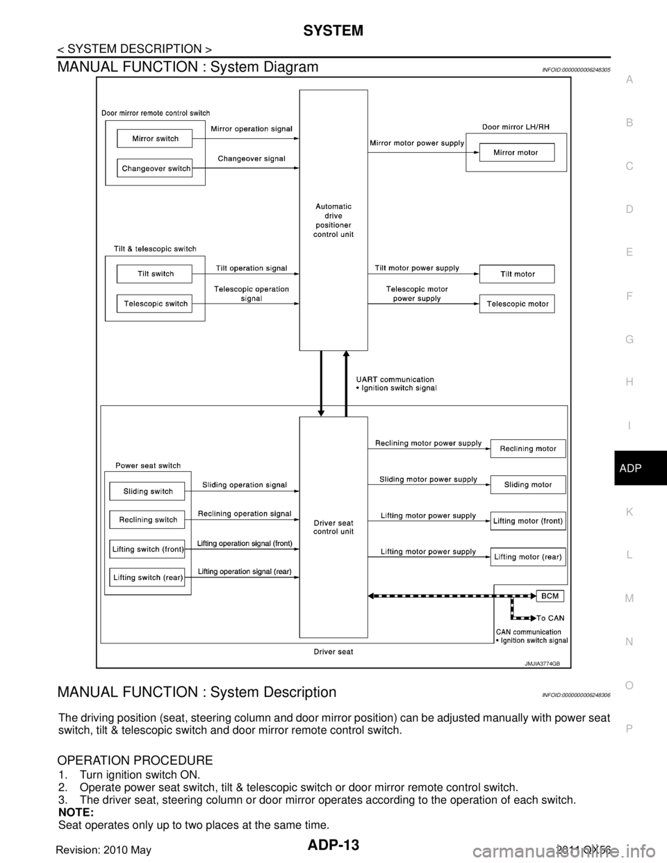
MANUAL FUNCTION : System DiagramINFOID:0000000006248305
MANUAL FUNCTION : System DescriptionINFOID:0000000006248306
The driving position (seat, steering column and door mi rror position) can be adjusted manually with power seat
switch, tilt & telescopic switch and door mirror remote control switch.
OPERATION PROCEDURE
1. Turn ignition switch ON.
2. Operate power seat switch, tilt & telescopic switch or door mirror remote control switch.
3. The driver seat, steering column or door mirror operates according to the operation of each switch.
NOTE:
Seat operates only up to two places at the same time.
JMJIA3774GB
Revision: 2010 May2011 QX56
Page 23 of 5598

ADP-14
< SYSTEM DESCRIPTION >
SYSTEM
DETAIL FLOW
Seat
NOTE:
The power seat can be operated manually regardless of the ignition switch position.
Tilt & Telescopic
Door Mirror
NOTE:
The door mirrors can be operated manually when ignition switch is in either ACC or ON position.
MEMORY FUNCTION
Order Input Output Control unit condition
1 Power seat switch
(sliding, lifting, reclin-
ing)
—The power seat switch signal is inputted to the driver seat control
unit when the power seat switch is operated.
2— Motors
(sliding, lifting, reclin-
ing)The driver seat control unit outputs signals to each motor accord-
ing to the power seat switch input signal.
Order Input Output Control unit condition
1 Tilt & telescopic switch — The tilt & telescopic switch signal is inputted to the automatic
drive positioner control unit when the tilt & telescopic switch is op-
erated.
2— Motors
(Tilt, telescopic)The automatic drive positioner control unit actuates each motor
according to the operation of the tilt & telescopic switch.
Order Input Output Control unit condition
1 Door mirror remote
control switch — The door mirror remote control switch signal is inputted to the au-
tomatic drive positioner control unit when the door mirror remote
control switch is operated.
2— Motors
(Door mirror motor)The automatic drive positioner control unit actuates each motor
according to the operation of the door mirror remote control switch.
Revision: 2010 May2011 QX56
Page 24 of 5598
SYSTEMADP-15
< SYSTEM DESCRIPTION >
C
DE
F
G H
I
K L
M A
B
ADP
N
O P
MEMORY FUNCTION : System DiagramINFOID:0000000006248307
MEMORY FUNCTION : System DescriptionINFOID:0000000006248308
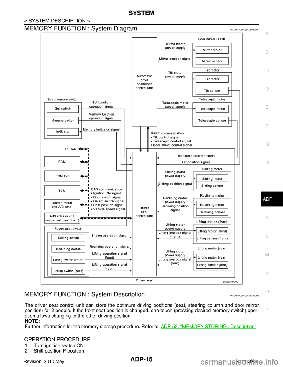
The driver seat control unit can store the optimum driving positions (seat, steering column and door mirror
position) for 2 people. If the front seat position is changed, one-touch (pressing desired memory switch) oper-
ation allows changing to the other driving position.
NOTE:
Further information for the memory storage procedure. Refer to ADP-53, "
MEMORY STORING : Description".
OPERATION PROCEDURE
1. Turn ignition switch ON.
2. Shift position P position.
JMJIA3775GB
Revision: 2010 May2011 QX56
Page 25 of 5598

ADP-16
< SYSTEM DESCRIPTION >
SYSTEM
3. Push desired memory switch.
4. Driver seat, steering and door mirror will move to the memorized position.
OPERATION CONDITION
Satisfy all of the following items. The memory function is not performed if these items are not satisfied.
* : When timer function does not operate.
DETAIL FLOW
TIMER FUNCTION
The memory function can be performed for 45 seconds after opening the driver door even if the ignition
switch position is in OFF position.
Satisfy all of the following items. The timer functi on is not performed if these items are not satisfied.
Item Request status
Ignition position ON
*
Switch inputs
Power seat switch
Tilt & telescopic switch
Door mirror control switch
Set switch
Memory switchOFF
(Not operated)
A/T shift selector P position
Memory function Registered
Vehicle speed 0 Km/h (0 MPH)
CONSULT-III Not connected
Order Input Output Control unit condition
1 Memory switch — The memory switch signal is inputted to the driver seat control unit
when memory switch 1 or 2 is operated.
2— Motors
(Seat, Steering,
door mirror)Driver seat control unit operates each motor of seat when it recogniz-
es the memory switch pressed for 0.5 second or more and requests
each motor operation to automatic drive positioner control unit via
UART communication. The automatic drive positioner control unit op-
erates each motor.
Memory switch Indica-
tor Driver seat control unit requests the flashing of memory indicator
while either of the motors is operating. The driver seat control unit il-
luminates the memory indicator.
3 Sensors
(Seat, steering col-
umn, door mirror) —Driver seat control unit judges the operating seat position with each
seat sensor input. The positions of the steering column and outside
mirror are monitored with each sensor signal. Driver seat control unit
stops the operation of each motor when each part reaches the record-
ed address.
4— Memory switch Indica-
torDriver seat control unit requests the illumination of memory indicator
after all motors stop. The driver seat control unit illuminates the mem-
ory indicator for 5 seconds.
Item Request status
Ignition position OFF
Set switch/memory switch OFF
Memory function Registered
A/T shift selector P position
Steering lock unit status LOCK
Driver side door switch OFF
CUNSULT-III Not connected
Revision: 2010 May2011 QX56
Page 26 of 5598
SYSTEMADP-17
< SYSTEM DESCRIPTION >
C
DE
F
G H
I
K L
M A
B
ADP
N
O P
EXIT ASSIST FUNCTION
EXIT ASSIST FUNCTION : System DiagramINFOID:0000000006248309
EXIT ASSIST FUNCTION : System DescriptionINFOID:0000000006248310
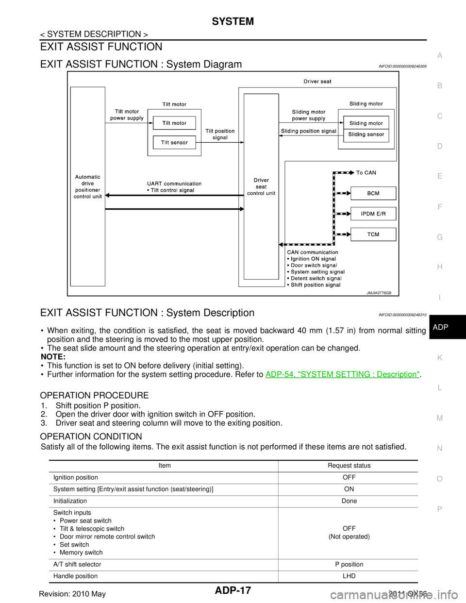
When exiting, the condition is satisfied, the seat is moved backward 40 mm (1.57 in) from normal sitting
position and the steering is moved to the most upper position.
The seat slide amount and the steering oper ation at entry/exit operation can be changed.
NOTE:
This function is set to ON before delivery (initial setting).
Further information for the system setting procedure. Refer to ADP-54, "
SYSTEM SETTING : Description".
OPERATION PROCEDURE
1. Shift position P position.
2. Open the driver door with ignition switch in OFF position.
3. Driver seat and steering column will move to the exiting position.
OPERATION CONDITION
Satisfy all of the following items. The exit assist function is not performed if these items are not satisfied.
JMJIA3776GB
Item Request status
Ignition position OFF
System setting [Entry/exit assist function (seat/steering)] ON
Initialization Done
Switch inputs
Power seat switch
Tilt & telescopic switch
Door mirror remote control switch
Set switch
Memory switch OFF
(Not operated)
A/T shift selector P position
Handle position LHD
Revision: 2010 May2011 QX56