rear view mirror INFINITI QX56 2011 Factory Service Manual
[x] Cancel search | Manufacturer: INFINITI, Model Year: 2011, Model line: QX56, Model: INFINITI QX56 2011Pages: 5598, PDF Size: 94.53 MB
Page 16 of 5598
COMPONENT PARTSADP-7
< SYSTEM DESCRIPTION >
C
DE
F
G H
I
K L
M A
B
ADP
N
O P
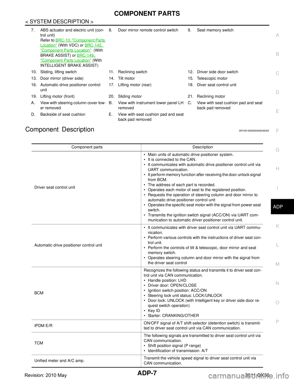
Component DescriptionINFOID:0000000006248302
7. ABS actuator and electric unit (con- trol unit)
Refer to BRC-10, "
Component Parts
Location" (With VDC) or BRC-142,
"Component Parts Location" (With
BRAKE ASSIST) or BRC-149,
"Component Parts Location" (With
INTELLIGENT BRAKE ASSIST) 8. Door mirror remote
control switch 9. Seat memory switch
10. Sliding, lifting switch 11. Reclining switch 12. Driver side door switch
13. Door mirror (driver side) 14. T ilt motor 15. Telescopic motor
16. Automatic drive positioner control unit 17. Lifting motor (rear) 18.
Diver seat control unit
19. Lifting motor (front) 20. Sliding motor 21. Reclining motor
A. View with steering column cover low- er removed B. View with instrument lower panel LH
removed C. View with seat cushion pad and seat
back pad removed
D. Backside of seat cushion E. View with seat cushion pad and seat back pad removed
Component parts Description
Driver seat control unit Main units of automatic drive positioner system.
It is connected to the CAN.
It communicates with automatic drive positioner control unit via
UART communication.
It perform memory function after receiving the door unlock signal
from BCM.
The address of each part is recorded.
Operates each motor of seat to the registered position.
Requests the operation of steering column and door mirror to automatic drive positioner control unit
Operates the specific seat motor with the signal from power seat
switch.
Transmits the ignition switch signal (ACC/ON) via UART com- munication to automatic driver positioner control unit.
Automatic drive positioner control unit It communicates with driver seat control unit via UART commu-
nication.
Perform various controls with the instructions of driver seat con- trol unit.
Perform the controls of tilt & telescopic, door mirror and seat memory switch.
Operates steering column and door mirror with the signal from the driver seat control
BCM Recognizes the following status and transmits it to driver seat con-
trol unit via CAN communication.
Handle position: LHD
Driver door: OPEN/CLOSE
Ignition switch position: ACC/ON
Steering lock unit status: LOCK/UNLOCK
Door lock: UNLOCK (with Intelligent key or driver side door re-
quest switch operation)
Key ID
Starter: CRANKING/OTHER
IPDM E/R ON/OFF signal of A/T shift selector (detention switch) is transmit-
ted to driver seat control unit via CAN communication.
TCM The following signals are transmitted to driver seat control unit via
CAN communication.
Shift position signal (P range)
Identification of transmission: A/T
Unified meter and A/C amp. Transmit the vehicle speed signal to driver seat control unit via
CAN communication.
Revision: 2010 May2011 QX56
Page 167 of 5598
AV
SYSTEMAV-19
< SYSTEM DESCRIPTION >
C
DE
F
G H
I
J
K L
M B A
O P
HANDS-FREE PHONE FUNCTION
AV control unit includes hands-free phone function.
Hands-free communication can be oper ated by connecting using Bluetooth
™ communication with cellular
phone.
Operation is performed by steering switch, and operating condition is indicated on display.
Guide sound that is heard during operation is input fr om AV control unit to BOSE amp., and is output from
front speaker and center speaker.
When A Call Is Originated
Spoken voice sound output from the microphone (microphone signal ) is input to AV control unit. AV control unit
outputs to cellular phone with Bluetooth
™ communication as a TEL voice signal. Voice sound is then heard at
the other party.
When Receiving A Call
Voice sound is input to own cellular phone from the other party. TEL voice signal is output to door speaker, and
the signal is input to BOSE amp. via AV control unit by establishing Bluetooth
™ communication from cellular
phone.
TOUCH PANEL SYSTEM
Each operation of multi AV system can be perfo rmed by directly touching a front display.
AROUND VIEW MONITOR FUNCTION
This system is equipped with wide-angle high-resolution cameras on the front and rear of the vehicle and on
both right and left door mirrors. The images from front view, rear view, front-side view (RH side), and birds-
eye view that shows the view from the top of the vehicle are displayed to monitor the vehicle surroundings.
Around view monitor control unit cuts out and expands the image received from each camera to create each view.
The sonar indicator is displayed on display (superimposed on the camera image) in combination with the
camera assistance sonar system to warm of the approach of an obstacle.
In front view and rear view, the vehicle width, dist ance lines and predictive course lines are superimposed
and displayed. In front-side view, the vehicle distance guiding line and vehicle width guiding line are dis-
played.
The Birds-Eye view converts the images from 4 cameras into the overhead view and displays the status of
the vehicle on display. The vehicle icon and sonar indica tor that are displayed on the Birds-Eye view display
are rendered by around view monitor control unit.
Around View Monitor Screen
Around view monitor combines and displays the travel di rection view and “Birds-Eye view”, “Front-Side view”
and then it displays the sonar indicator on the “Birds -Eye view”, “Front-Side view”, “Rear wide view”.
AV control unit renders the “Change View” switch, view icon, warning message on display.
Revision: 2010 May2011 QX56
Page 170 of 5598

AV-22
< SYSTEM DESCRIPTION >
SYSTEM
Front view guiding lines
REAR VIEW The rear view image is from the rear camera.
When the selector lever is in the reverse position, the rear view is displayed. Backing and parking are
improved by the images from Birds-Eye view and Front-S ide view. The rear wide view function allows the
display of an image with a 180 ° horizontal angle.
Display the vehicle width guiding line and vehicle distance guiding line in Rear view and display the predic- tive course line according to the steering angle (except when using the rear wide view function).
The predictive course line is not di splayed at the steering neutral position.
AV control unit is connected to the steering angle s ensor and receives the steering angle signal via CAN
communication. AV control unit is transmits steering angle signal to around view monitor control unit via AV
communication.
Around view monitor control unit controls the direction and distance of predictive course line according to the
sensor signal from steering angle sensor.
Rear view guiding lines
FRONT-SIDE VIEW
The front-side view image is from the side camera RH.
In Front-Side view, display the vehicle distance guiding line and vehicle width guiding line.
The infrared LED illumination is installed on the door mirror RH to illuminate around the front wheels.
JSNIA0770GB
JSNIA2984GB
Revision: 2010 May2011 QX56
Page 193 of 5598

AV
DIAGNOSIS SYSTEM (AROUND VIEW MONITOR CONTROL UNIT)
AV-45
< SYSTEM DESCRIPTION >
C
D E
F
G H
I
J
K L
M B A
O P
Calibrating Camera Image
Perform the calibration of camera image caused by the incorrect mounting position of each camera, etc. Always perform calibration
after performing the following work.
- When each camera or each camera mount (door mirror, front grille,
etc.) is removed
- When replacing around view monitor control unit
When performing the calibration initialization, it can be set to the
NISSAN factory shipment condition.
Refer to AV-112, "
Work Procedure" for the calibration procedure.
Calibrating Camera Image item
CAUTION:
Type of Steer. Angle Sensor Abslt. The input type of steering angle sensor is displayed. (“Abslt.” is displayed on this
model.)
Type of Steer. Gear ratio 1 The type of steering gear ratio is displayed. (“1” is displayed on this model.)
Left or Right Steer. Right/Left The steering position is displayed.
Rear Camera Image Output signal OK/NG The input status of rear camera image signal is displayed by OK/NG in real time.
Rear Camera COMM Status OK/NG The communication status with rear camera is displayed by OK/NG in real time.
Rear Camera COMM Line OK/NG The status of communication line with rear camera is displayed by OK/NG in real
time.
Front Camera Image Output signal OK/NG The input status of front camera image signal is displayed by OK/NG in real time.
Front Camera COMM Status OK/NG The communication status with front camera is displayed by OK/NG in real time.
Front Camera COMM Line OK/NG The status of communication line with front camera is displayed by OK/NG in real
time.
Pass-Side Camera Image Output sig-
nal OK/NGThe input status of side camera RH image signal is displayed by OK/NG in real
time.
Pass-Side Camera COMM Status OK/NG The communication status with side camera RH is displayed by OK/NG in real
time.
Pass-Side Camera COMM Line OK/NG The status of communication line with side camera RH is displayed by OK/NG in
real time.
Dr-Side Camera Image Output signal OK/NG The input status of side camera LH image signal is displayed by OK/NG in real
time.
Dr-Side Camera COMM Status OK/NG The communication status with side camera LH is displayed by OK/NG in real
time.
Dr-Side Camera COMM Line OK/NG The status of communication line with side camera LH is displayed by OK/NG in
real time.
Diagnosis item Display Description
JSNIA2379ZZ
Adjustment range
Rotating direction : 31 patterns (16 on the center)
Upper/lower direction : (
−99) – (+99)
Left/right direction : ( −99) – (+99)
Items Description
Rear Camera Performs the ca libration of rear camera.
Pass-Side Camera Performs the ca libration of side camera RH.
Front Camera Performs the ca libration of front camera.
Dr-Side Camera Performs the calib ration of side camera LH.
Initialize Camera Image Calibration
*The calibration can be initialized to the factory shipment setting.
Revision: 2010 May2011 QX56
Page 335 of 5598

AV
SIDE CAMERA LH COMMUNICATION SIGNAL CIRCUIT
AV-187
< DTC/CIRCUIT DIAGNOSIS >
C
D E
F
G H
I
J
K L
M B A
O P
SIDE CAMERA LH COMMUNI CATION SIGNAL CIRCUIT
DescriptionINFOID:0000000006216358
Around view monitor control unit supplies to the front camera, rear camera and side camera. And then it
superimpose the images from each camera and outputs then to the front display unit.
Superimpose the guiding lines, predictive course line and sonar indicator to the camera image that outputs
to the front display unit.
Around view monitor control unit performs the rec eption/transmission of communication signal with each
camera.
Diagnosis ProcedureINFOID:0000000006216359
1.CHECK CONTINUITY COMMUNI CATION SIGNAL CIRCUIT
1. Turn ignition switch OFF.
2. Disconnect around view monitor control unit connector and door mirror (driver side) connector.
3. Check continuity between around view monitor control unit harness connector and door mirror (driver side) harness connector.
4. Check continuity between around view monitor control unit harness connector and ground.
Is inspection result normal?
YES >> GO TO 2.
NO >> Repair harness or connector.
2.CHECK COMMUNICATION SIGNAL
1. Connect around view monitor control unit c onnector and door mirror (driver side) connector.
2. Turn ignition switch ON.
3. Check signal between around view monitor control unit harness connector and ground.
Is inspection result normal?
YES >> Replace around view monitor control unit. Refer to AV-233, "Removal and Installation".
NO >> Replace side camera LH. Refer to AV-236, "
Removal and Installation".
Around view monitor control
unit Door mirror
(driver side) Continuity
Connector Terminal Connector Terminal
M49 47 D3 3 Existed
Around view monitor control unit GroundContinuity
Connector Terminal
M49 47 Not existed
(+)
(− ) Condition Reference value
Around view monitor control
unit
Connector Terminal
M49 47 Ground “CAMERA” switch is ON or shift
position is “R”.
JSNIA0836GB
Revision: 2010 May2011 QX56
Page 336 of 5598

AV-188
< DTC/CIRCUIT DIAGNOSIS >
SIDE CAMERA LH IMAGE SIGNAL CIRCUIT
SIDE CAMERA LH IMAGE SIGNAL CIRCUIT
DescriptionINFOID:0000000006216360
Around view monitor control unit supplies to the front camera, rear camera and side came\
ra. And then itsuperimpose the images from each camera and outputs then to the front display unit.
Superimpose the guiding lines, predictive course line and sonar indicator to the camera image that outputs
to the front display unit.
Around view monitor control unit performs the rec eption/transmission of communication signal with each
camera.
Diagnosis ProcedureINFOID:0000000006216361
1.CHECK CONTINUITY SIDE CAMERA LH POWER SUPPLY AND GROUND CIRCUIT
1. Turn ignition switch OFF.
2. Disconnect around view monitor control unit connector and door mirror (driver side) connector.
3. Check continuity between around view monitor c ontrol unit harness connector and door mirror (driver
side) harness connector.
4. Check continuity between around view m onitor control unit harness connector and ground.
Is inspection result normal?
YES >> GO TO 2.
NO >> Repair harness or connector.
2.CHECK VOLTAGE SIDE CA MERA LH POWER SUPPLY
1. Connect around view monitor control unit connector and door mirror (driver side) connector.
2. Turn ignition switch ON.
3. Check voltage between around view monito r control unit harness connector and ground.
Is inspection result normal?
YES >> GO TO 3.
NO >> Replace around view monitor control unit. Refer to AV-233, "
Removal and Installation".
3.CHECK CONTINUITY SIDE CAMERA LH IMAGE SIGNAL CIRCUIT
1. Turn ignition switch OFF.
2. Disconnect around view monitor control unit connector and door mirror (driver side) connector.
3. Check continuity between around view monitor c ontrol unit harness connector and door mirror (driver
side) harness connector.
Around view monitor control
unit Door mirror (driver side)
Continuity
Connector Terminals Connector Terminals
M49 48
D3 6
Existed
50 18
Around view monitor control unit GroundContinuity
Connector Terminal
M49 48 Not existed
(+)
(− ) Condition Vo l ta g e
(Approx.)
Around view monitor control
unit
Connector Terminal
M49 48 Ground “CAMERA” switch is ON or
shift position is “R”.
6.0 V
Revision: 2010 May2011 QX56
Page 338 of 5598
AV-190
< DTC/CIRCUIT DIAGNOSIS >
SIDE CAMERA RH COMMUNICATION SIGNAL CIRCUIT
SIDE CAMERA RH COMMUNICATION SIGNAL CIRCUIT
DescriptionINFOID:0000000006216362
Around view monitor control unit supplies to the front camera, rear camera and side came\
ra. And then it
superimpose the images from each camera and outputs then to the front display unit.
Superimpose the guiding lines, predictive course line and sonar indicator to the camera image that outputs
to the front display unit.
Around view monitor control unit performs the rec eption/transmission of communication signal with each
camera.
Diagnosis ProcedureINFOID:0000000006216363
1.CHECK CONTINUITY COMMUNI CATION SIGNAL CIRCUIT
1. Turn ignition switch OFF.
2. Disconnect around view monitor control unit c onnector and door mirror (passenger side) connector.
3. Check continuity between around view monitor c ontrol unit harness connector and door mirror (passenger
side) harness connector.
4. Check continuity between around view m onitor control unit harness connector and ground.
Is inspection result normal?
YES >> GO TO 2.
NO >> Repair harness or connector.
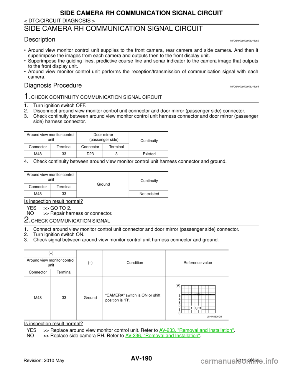
2.CHECK COMMUNICATION SIGNAL
1. Connect around view monitor control unit connector and door mirror (passenger side) connector.
2. Turn ignition switch ON.
3. Check signal between around view monitor control unit harness connector and ground.
Is inspection result normal?
YES >> Replace around view monitor control unit. Refer to AV-233, "Removal and Installation".
NO >> Replace side camera RH. Refer to AV-236, "
Removal and Installation".
Around view monitor control
unit Door mirror
(passenger side) Continuity
Connector Terminal Connector Terminal
M48 33 D23 3 Existed
Around view monitor control unit GroundContinuity
Connector Terminal
M48 33 Not existed
(+)
(− ) Condition Reference value
Around view monitor control
unit
Connector Terminal
M48 33 Ground “CAMERA” switch is ON or shift
position is “R”.
JSNIA0836GB
Revision: 2010 May2011 QX56
Page 339 of 5598
AV
SIDE CAMERA RH IMAGE SIGNAL CIRCUITAV-191
< DTC/CIRCUIT DIAGNOSIS >
C
DE
F
G H
I
J
K L
M B A
O P
SIDE CAMERA RH IM AGE SIGNAL CIRCUIT
DescriptionINFOID:0000000006216364
Around view monitor control unit supplies to the front camera, rear camera and side camera. And then it
superimpose the images from each camera and outputs then to the front display unit.
Superimpose the guiding lines, predictive course line and sonar indicator to the camera image that outputs
to the front display unit.
Around view monitor control unit performs the rec eption/transmission of communication signal with each
camera.
Diagnosis ProcedureINFOID:0000000006216365
1.CHECK CONTINUITY SIDE CAMERA RH POWER SUPPLY AND GROUND CIRCUIT
1. Turn ignition switch OFF.
2. Disconnect control unit connector and door mirror (passenger side) connector.
3. Check continuity between around view monitor c ontrol unit harness connector and door mirror (passenger
side) harness connector.
4. Check continuity between around view monitor control unit harness connector and ground.
Is inspection result normal?
YES >> GO TO 2.
NO >> Repair harness or connector.
2.CHECK VOLTAGE SIDE CAMERA RH POWER SUPPLY
1. Connect around view monitor control unit connec tor and door mirror (passenger side) connector.
2. Turn ignition switch ON.
3. Check voltage between around view monitor control unit harness connector and ground.
Is inspection result normal?
YES >> GO TO 3.
NO >> Replace around view monitor control unit. Refer to AV-233, "
Removal and Installation".
3.CHECK CONTINUITY SIDE CAMERA RH IMAGE SIGNAL CIRCUIT
1. Turn ignition switch OFF.
2. Disconnect around view monitor control unit connec tor and door mirror (passenger side) connector.
3. Check continuity between around view monitor c ontrol unit harness connector and door mirror (passenger
side) harness connector.
Around view monitor control
unit Door mirror
(passenger side) Continuity
Connector Terminals Connector Terminals
M48 32
D23 18
Existed
34 6
Around view monitor control unit GroundContinuity
Connector Terminal
M48 34 Not existed
(+)
(− ) Condition Vo l ta g e
(Approx.)
Around view monitor control
unit
Connector Terminal
M48 34 Ground “CAMERA” switch is ON or
shift position is “R”.
6.0 V
Revision: 2010 May2011 QX56
Page 383 of 5598

AV
REAR CAMERAAV-235
< REMOVAL AND INSTALLATION >
C
DE
F
G H
I
J
K L
M B A
O P
REAR CAMERA
Removal and InstallationINFOID:0000000006216400
REMOVAL
1. Remove back door finisher center upper. Refer to EXT-44, "Exploded View".
2. Remove rear camera mounting screws to remove rear camera.
INSTALLATION
1. Install in the reverse order of removal.
2. Perform camera image calibration. Refer to AV-112, "
Work Procedure".
CAUTION:
Perform the calibration and perfo rm the writing to the around view monitor control unit when remov-
ing and replacing each camera, remo ving the camera mounting parts (front grille, door mirror, etc.)
and replacing the around vi ew monitor control unit.
Revision: 2010 May2011 QX56
Page 2986 of 5598
GI-22
< HOW TO USE THIS MANUAL >
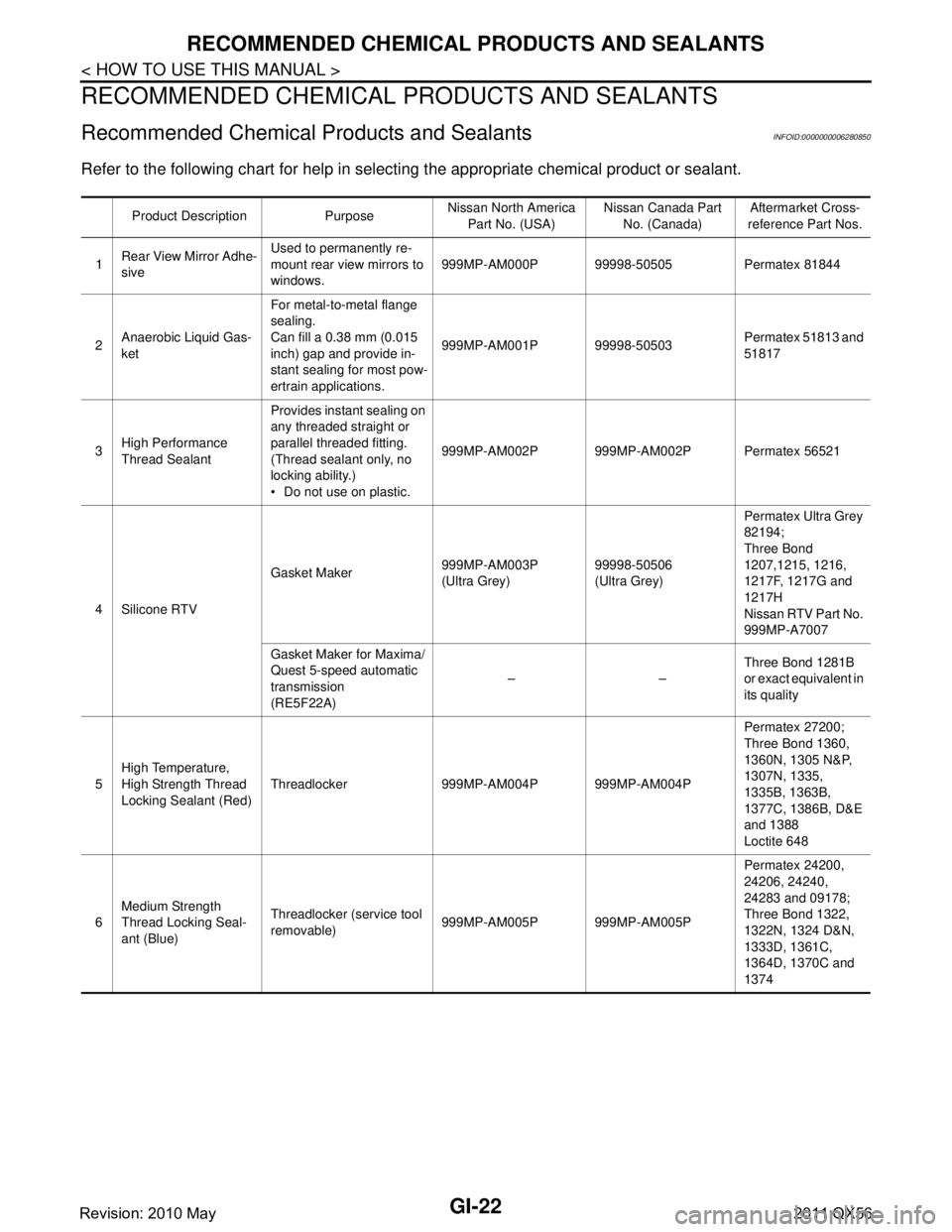
RECOMMENDED CHEMICAL PRODUCTS AND SEALANTS
RECOMMENDED CHEMICAL PRODUCTS AND SEALANTS
Recommended Chemical Products and SealantsINFOID:0000000006280850
Refer to the following chart for help in selecting the appropriate chemical product or sealant.
Product Description Purpose Nissan North America
Part No. (USA) Nissan Canada Part
No. (Canada) Aftermarket Cross-
reference Part Nos.
1 Rear View Mirror Adhe-
sive Used to permanently re-
mount rear view mirrors to
windows.
999MP-AM000P 99998-50505 Permatex 81844
2 Anaerobic Liquid Gas-
ket For metal-to-metal flange
sealing.
Can fill a 0.38 mm (0.015
inch) gap and provide in-
stant sealing for most pow-
ertrain applications.
999MP-AM001P 99998-50503
Permatex 51813 and
51817
3 High Performance
Thread Sealant Provides instant sealing on
any threaded straight or
parallel threaded fitting.
(Thread sealant only, no
locking ability.)
Do not use on plastic.
999MP-AM002P 999MP-AM002P Permatex 56521
4 Silicone RTV Gasket Maker
999MP-AM003P
(Ultra Grey)99998-50506
(Ultra Grey)Permatex Ultra Grey
82194;
Three Bond
1207,1215, 1216,
1217F, 1217G and
1217H
Nissan RTV Part No.
999MP-A7007
Gasket Maker for Maxima/
Quest 5-speed automatic
transmission
(RE5F22A) ––
Three Bond 1281B
or exact equivalent in
its quality
5 High Temperature,
High Strength Thread
Locking Sealant (Red)
Threadlocker 999MP-AM004P 999MP-AM004P Permatex 27200;
Three Bond 1360,
1360N, 1305 N&P,
1307N, 1335,
1335B, 1363B,
1377C, 1386B, D&E
and 1388
Loctite 648
6 Medium Strength
Thread Locking Seal-
ant (Blue) Threadlocker (service tool
removable)
999MP-AM005P 999MP-AM005P Permatex 24200,
24206, 24240,
24283 and 09178;
Three Bond 1322,
1322N, 1324 D&N,
1333D, 1361C,
1364D, 1370C and
1374
Revision: 2010 May2011 QX56