12V ISUZU KB P190 2007 Workshop Repair Manual
[x] Cancel search | Manufacturer: ISUZU, Model Year: 2007, Model line: KB P190, Model: ISUZU KB P190 2007Pages: 6020, PDF Size: 70.23 MB
Page 586 of 6020

4C2-8 SHIFT ON THE FLY SYSTEM
RTW 440SH000201
Clutch Gear
Visual Check
Check and see the there is not wear, damage, crack, o
r
any other abnormality in the clutch gear.
Functional Check
If there is an abnormality such as smooth less when
operated in combination with sleeve, replace the clutch
gear.
NOTE:
When inspection, gear oil should be applied to the contact
surface of gear.
RTW 440SH000301
Dimensional Check
Make sure of the size illustrated.
Clutch Gear Out Side Diameter (Limit) mm (in)
36.98 (1.46)
RTW 440SH000501
RTW 440SH000401
Actuator
Visual Check
Check and see that there is no damage, cracking, or othe
r
abnormality.
Functional Check
Make sure of function with voltage (12V) applied to
terminal
3, 4 and set the tester to terminal 1, 2 in
accordance with the table below.
State Port 3Port 4Port 1, 2
Conducting Function
A
+ −
−−
−
C
B −
−−
−
+ × D
If there is an abnormality, replace the actuator as an
assembly.
NOTE:
Be careful not to permit the entry of water or dust into the ports
of the actuator.
Do not open the actuator cover, if the actuator will be reused.
BACK TO CHAPTER INDEX
TO MODEL INDEX
ISUZU KB P190 2007
Page 634 of 6020

BRAKE CONTROL SYSTEM 5A-41
Wheel Speed Sensor Inspection Procedure
Procedure
1.Ignition "OFF".
2.Disconnect each of the wheel speed sensors.
3.Connect the resistance (50 Ω~100 Ω) as follows.
4.Check the voltage at sensor harness connector.
Note: Voltage measurement is performed in the phase
where the wheel speed sensor is installed in vehicles.
RTW 75AMF000701
Connector Pin-outs
・Front W heel Speed Sensor
1 (+) (+12V)
2 (-) (signal)
・Rear W heel Speed Sensor
1 LH (+) (+12V)
2 LH (-) (signal)
3 RH (+)(+12V)
4 RH (-) (signal)
Output Value
High State 0.7~1.4V (±30%)
Low State 0.4~0.7V (±30%)
BACK TO CHAPTER INDEX
TO MODEL INDEX
ISUZU KB P190 2007
Page 1015 of 6020

6D – 14 ENGINE ELECTRICAL
RECTIFIER ASSEMBLY
RTW46DSF000301
1. Voltmeter
2. Switch 1
3. DC regulated power supply
4. Lamp 2
5. Lamp 1
6. Switch 3
7. Switch 2
8. Pulse generator
9. Output signal
Test circuit
Refer to the judgment criteria shown in the Table below.
Carefully check Items 1~5. If all the items are OK, the IC
regulator is normal.
Circuit components
1 DC regulated power supply 0~20 volts variable with output of 1 ampere or more
2 Lamps (2)
12 volts, 1.4~3.4 watts
3 Switches (3)
-----
4 DC voltmeter
0~30 volts, 0.5 grade
5 Pulse generator (Oscillator)
5~30 volt output at a frequency of 1kHz
Judgment criteria
Lamp condition
No. Switch
1 Switch
2 Switch
3 Voltmeter
reading Lamp 1 Lamp 2 Remarks
1
ON OFF OFF On
(dim) ON Initial excitation check
2
ON ON OFF 12V
On or
flashing Full excitation check
3
ON ON OFF 16V Off or
on (dim) OFF
Lamp 1 off or dimly lit when the
voltmeter shows less than 12 volts or
16 volts
4 OFF ON OFF 12V On or
flashing Stator and brush separation check
5
ON ON ON 18V On ON
Excess voltage check
BACK TO CHAPTER INDEX
TO MODEL INDEX
ISUZU KB P190 2007
Page 1601 of 6020

ENGINE ELECTRICAL (4JK1/4JJ1) 6D-13
Rectifier
Measure each of the diode resistances in both
directions (anode/cathode and cathode/anode). If any o
f
the diodes have the same resistance in both directions,
the rectifier must be replaced.
066RS036
Regulator Assembly
There are 3 checkpoints (12V batteries, 10 ohms 3W
resistor, 0-50V/0.5V steps, and 300 ohms 12W variable
resistor). Refer to the schematic below.
Measuring Procedure
1. Measure the voltage (BAT) at the V1 checkpoint. A
10-13 volt reading indicates that the BAT battery is
good.
2. Measure the voltage at checkpoints V1 and V2 as
you gradually increase the resistance of the
variable resistor from 0. The voltage at V1 should
change with the voltage at V2. If it does not, the
regulator is damaged and must be replaced.
3. Measure the voltage at checkpoint V3 with the variable resistor setting fixed. If the measured
voltage is 14.4 ± 0.3, the regulator is good. If the
measured voltage is outside this range, the
regulator is damaged and must be replaced.
RTW 56DMF000301
BACK TO CHAPTER INDEX
TO MODEL INDEX
ISUZU KB P190 2007
Page 2140 of 6020

ENGINE ELECTRICAL 6D1-3
Diagnosis
1. Visual Inspection
Inspect the battery for obvious physical damage, such as a
cracked or broken case, which would permit electrolyte loss.
Replace the battery if obvious physical damage is discovered
during inspection.
Check for any other physical damage and correct it as
necessary.
2. Hydrometer Check
3. Fluid Level Check
The fluid level should be between the upper level line (2) and
lower lever line (3) on side of battery.
a. CORRECT FLUID LEVEL - Charge the battery.
b. BELOW LOW ER LEVEL - Replace battery.
4. Voltage Check
1. Put voltmeter test leads to battery terminals. a. VOLTAGE IS 12.4V OR ABOVE - Go to Step 5.
b. VOLTAGE IS UNDER 12.4V - Go to procedure (2) below.
2. Determine fast charge amperage from specification.
(See Main Data and Specifications in this section).
Fast charge battery for 30 minutes at amperage rate no higher than specified value.
Take voltage and amperage readings after charge. a. VOLTAGE IS ABOVE 16V AT BELOW 1/3 OF AMPERAGE RATE - Replace battery.
b. VOLTAGE IS ABOVE 16V AT ABOVE 1/3 OF AMPERAGE RATE - Drop charging voltage to 15V and
charge for 10 - 15 hours. Then go to Step 5.
c. VOLTAGE IS BETW EEN 12V AND 16V - Continue charging at the same rate for an additional 3-1/2 hours.
Then go to Step 5.
d. VOLTAGE BELOW 12V - Replace Battery.
BACK TO CHAPTER INDEX
TO MODEL INDEX
ISUZU KB P190 2007
Page 2158 of 6020

6D3-10 STARTING AND CHARGING SYSTEM
The generator has four external connections; the "B+" lead to
battery positive, "L" lead to the warning lamp circuit(max. 2
watts), "S" lead to battery positive terminal for battery sensing
and an earth connection.
Explanation of type inscripiton
Example:KC-A--> 14V 50-90A.
K = Code for Stator OD(126mm OD).
C = Compact Generator.
A = Ausland (countries other than Germany)
> = Direction of rotation(clockwise).
14V = Generator Operating Voltage.
50A = Stabilised output at 25 C at 1800 RPM./13.5
Volts.
90A = Stabilised output at 25 C at 1800 RPM./13.5
Volts.
Generator Connetions.
B+ : Battery Main Connection (battery positive)
S : Battery Sense Connection(battery positive)
L : W aring lamp(via warning lamp to Ignition switch)
BATT.SENSE
REGULATOR ASSEMBLYHYBR10 ALTERNATOR ASSEMBLY
12V BATT. 1GN.SW .
300a*
W ARN.LAMP
1.2 W ATT L
S 8+
SUPPRESSOR
CAPACITOR
0.5 µf
NOTE: * RESISTOR IS RECOMMENDED TO
ENSURE THAT THE GENERATOR
REMAINS FUNCTIONAL IN CASE OF
W ARNING LAMP FAILURE
BACK TO CHAPTER INDEX
TO MODEL INDEX
ISUZU KB P190 2007
Page 3809 of 6020
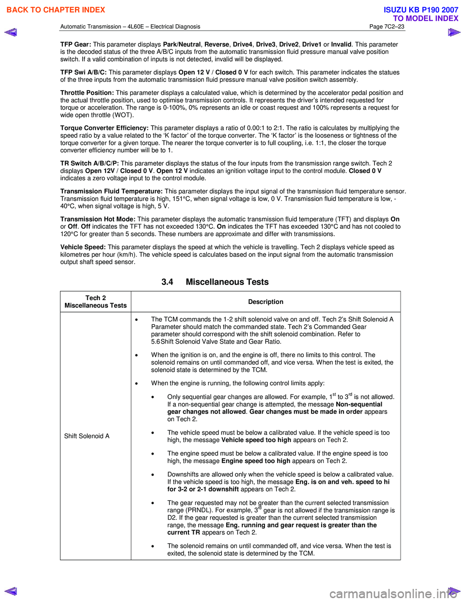
Automatic Transmission – 4L60E – Electrical Diagnosis Page 7C2–23
TFP Gear: This parameter displays Park/Neutral, Reverse , Drive4 , Drive3 , Drive2 , Drive1 or Invalid . This parameter
is the decoded status of the three A/B/C inputs from the automatic transmission fluid pressure manual valve position
switch. If a valid combination of inputs is not detected, invalid will be displayed.
TFP Swi A/B/C: This parameter displays Open 12 V / Closed 0 V for each switch. This parameter indicates the statues
of the three inputs from the automatic transmission fluid pressure manual valve position switch assembly.
Throttle Position: This parameter displays a calculated value, which is determined by the accelerator pedal position and
the actual throttle position, used to optimise transmission controls. It represents the driver’s intended requested for
torque or acceleration. The range is 0-100%, 0% represents an idle or coast request and 100% represents a request for
wide open throttle (WOT).
Torque Converter Efficiency: This parameter displays a ratio of 0.00:1 to 2:1. The ratio is calculates by multiplying the
speed ratio by a value related to the ‘K factor’ of the torque converter. The ‘K factor’ is the looseness or tightness of the
torque converter for a given torque. The nearer the torque converter is to full coupling, i.e. 1:1, the closer the torque
converter efficiency number will be to 1.
TR Switch A/B/C/P: This parameter displays the status of the four inputs from the transmission range switch. Tech 2
displays Open 12V / Closed 0 V . Open 12 V indicates an ignition voltage input to the control module. Closed 0 V
indicates a zero voltage input to the control module.
Transmission Fluid Temperature: This parameter displays the input signal of the transmission fluid temperature sensor.
Transmission fluid temperature is high, 151°C, when signal voltage is low, 0 V. Transmission fluid temperature is low, -
40°C, when signal voltage is high, 5 V.
Transmission Hot Mode: This parameter displays the automatic transmission fluid temperature (TFT) and displays On
or Off . Off indicates the TFT has not exceeded 130°C. On indicates the TFT has exceeded 130°C and has not cooled to
120°C for greater than 5 seconds. These numbers are approximate and differ with transmissions.
Vehicle Speed: This parameter displays the speed at which the vehicle is travelling. Tech 2 displays vehicle speed as
kilometres per hour (km/h). The vehicle speed is calculates based on the input signal from the automatic transmission
output shaft speed sensor.
3.4 Miscellaneous Tests
Tech 2
Miscellaneous Tests Description
Shift Solenoid A •
The TCM commands the 1-2 shift solenoid valve on and off. Tech 2’s Shift Solenoid A
Parameter should match the commanded state. Tech 2’s Commanded Gear
parameter should correspond with the shift solenoid combination. Refer to
5.6 Shift Solenoid Valve State and Gear Ratio.
• When the ignition is on, and the engine is off, there no limits to this control. The
solenoid remains on until commanded off, and vice versa. W hen the test is exited, the
solenoid state is determined by the TCM.
• W hen the engine is running, the following control limits apply:
• Only sequential gear changes are allowed. For example, 1
st to 3rd is not allowed.
If a non-sequential gear change is attempted, the message Non-sequential
gear changes not allowed . Gear changes must be made in order appears
on Tech 2.
• The vehicle speed must be below a calibrated value. If the vehicle speed is too
high, the message Vehicle speed too high appears on Tech 2.
• The engine speed must be below a calibrated value. If the engine speed is too
high, the message Engine speed too high appears on Tech 2.
• Downshifts are allowed only when the vehicle speed is below a calibrated value.
If the vehicle speed is too high, the message Eng. is on and veh. speed to hi
for 3-2 or 2-1 downshift appears on Tech 2.
• The gear requested may not be greater than the current selected transmission
range (PRNDL). For example, 3
rd gear is not allowed if the transmission range is
D2. If the gear requested is greater than the current selected transmission
range, the message Eng. running and gear request is greater than the
current TR appears on Tech 2.
• The solenoid remains on until commanded off, and vice versa. W hen the test is
exited, the solenoid state is determined by the TCM.
BACK TO CHAPTER INDEX
TO MODEL INDEX
ISUZU KB P190 2007
Page 3892 of 6020

Automatic Transmission – 4L60E – Electrical Diagnosis Page 7C2–106
Step Action Yes No
3 1 Connect Tech 2 to the DLC.
2 Turn on the ignition, with the engine off.
NOTE
Before clearing the DTC, use the Tech 2 Freeze
Frame/Failure Record to record the transmission
parameters at the time the DTC set. Using Tech 2 to clear
the DTC(s) erases the Freeze Frame/Failure Record
records from the TCM.
3 On Tech 2 select: Transmission / Automatic Transmission / Diagnostic
Trouble Codes / Freeze Frame.
4 Select the relevant DTC and note the parameters at the time of the DTC setting.
5 On Tech 2 select:
Diagnostic Trouble Codes / Clear Engine & Transmission
DTCs.
6 Follow the instructions on Tech 2 and clear the DTCs.
7 Start the engine and idle at normal operating temperature.
8 Apply the brake pedal.
9 On Tech 2 select: Data Display / Transmission Data.
10 Select each transmission range: P, R, N, D4, D3, D2 and D1.
Does each selected transmission range match the TFP Gear
displayed on Tech 2? Check for an
intermittent fault in
the circuit, refer to
8A Electrical-Body and Chassis Go to Step 4
4 1 Turn off the ignition.
2 Disconnect connector E-95 from the transmission.
NOTE
Additional DTCs may set.
3 Turn on the ignition, with the engine off.
Does Tech 2 display Open 12V for any of the TFP Switch. A/B/C
parameters? Go to Step 5 Go to Step 7
5 1 Turn off the ignition.
2 Install Tool No. J 44152 Jumper Harness (20 pins) on to the harness connector E-95.
3 Turn on the ignition, with the engine off.
4 Using a multimeter set to measure voltage, probe between the following pins and ground:
• connector E-95 pin 5,
• connector E-95 pin 13, and
• connector E-95 pin 12.
Did the multimeter display 10 – 12 V for all the tests? Go to Step 6 Go to Step 8
BACK TO CHAPTER INDEX
TO MODEL INDEX
ISUZU KB P190 2007
Page 4263 of 6020
7A1-24 CONSTRUCTION AND FUNCTION
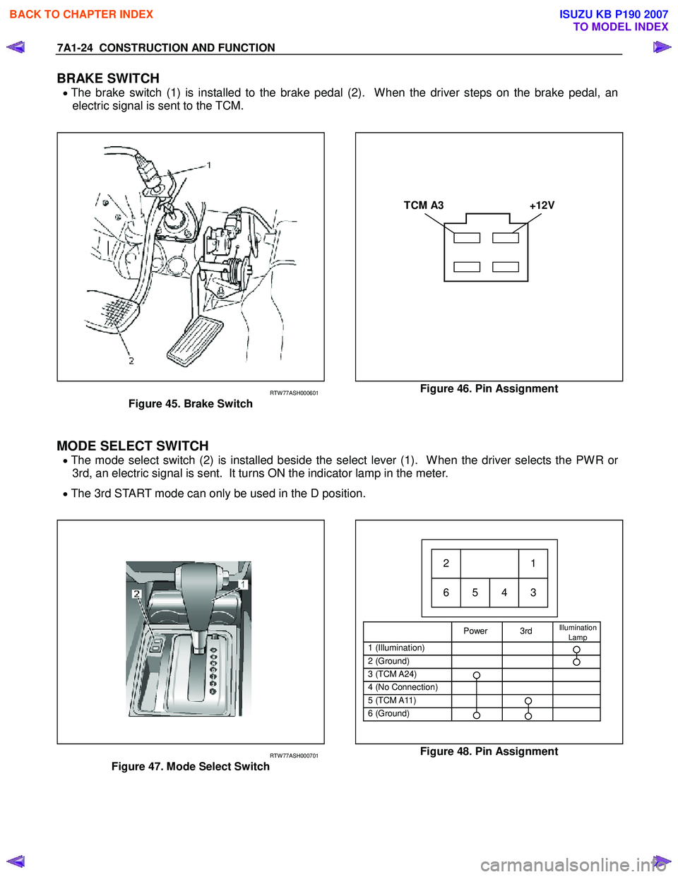
BRAKE SWITCH
• The brake switch (1) is installed to the brake pedal (2). When the driver steps on the brake pedal, an
electric signal is sent to the TCM.
TCM A3 +12V
RTW 77ASH000601
Figure 45. Brake Switch
Figure 46. Pin Assignment
MODE SELECT SWITCH
• The mode select switch (2) is installed beside the select lever (1). When the driver selects the PWR or
3rd, an electric signal is sent. It turns ON the indicator lamp in the meter.
• The 3rd START mode can only be used in the D position.
Power 3rd Illumination
Lamp
1 (Illumination)
2 (Ground)
3 (TCM A24)
4 (No Connection)
5 (TCM A11)
6 (Ground)
21
65 4 3
RTW 77ASH000701
Figure 47. Mode Select Switch
Figure 48. Pin Assignment
BACK TO CHAPTER INDEX
TO MODEL INDEX
ISUZU KB P190 2007
Page 4954 of 6020
8A-16 ELECTRICAL-BODY AND CHASSIS
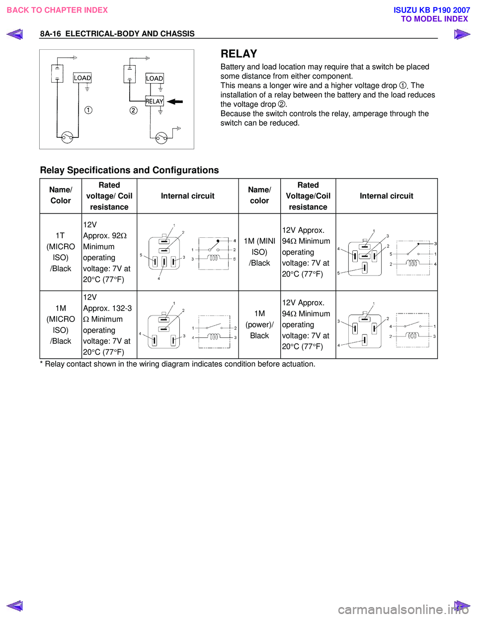
RELAY
Battery and load location may require that a switch be placed
some distance from either component.
This means a longer wire and a higher voltage drop
1. The
installation of a relay between the battery and the load reduces
the voltage drop
2.
Because the switch controls the relay, amperage through the
switch can be reduced.
Relay Specifications and Configurations
Name/ Color Rated
voltage/ Coil resistance Internal circuit
Name/
color Rated
Voltage/Coil resistance Internal circuit
1T
(MICRO ISO)
/Black 12V
Approx. 92 Ω
Minimum
operating
voltage: 7V at
20 °C (77 °F)
1M (MINI
ISO)
/Black 12V Approx.
94 Ω Minimum
operating
voltage: 7V at
20 °C (77 °F)
1M
(MICRO ISO)
/Black 12V
Approx. 132-3
Ω Minimum
operating
voltage: 7V at
20 °C (77 °F)
1M
(power)/ Black 12V Approx.
94 Ω Minimum
operating
voltage: 7V at
20 °C (77 °F)
* Relay contact shown in the wiring diagram indicates condition before actuation.
BACK TO CHAPTER INDEX TO MODEL INDEXISUZU KB P190 2007