12V ISUZU KB P190 2007 Workshop User Guide
[x] Cancel search | Manufacturer: ISUZU, Model Year: 2007, Model line: KB P190, Model: ISUZU KB P190 2007Pages: 6020, PDF Size: 70.23 MB
Page 5350 of 6020
8A-412 ELECTRICAL-BODY AND CHASSIS
INSPECTION AND REPAIR
Harness side
D20 D5
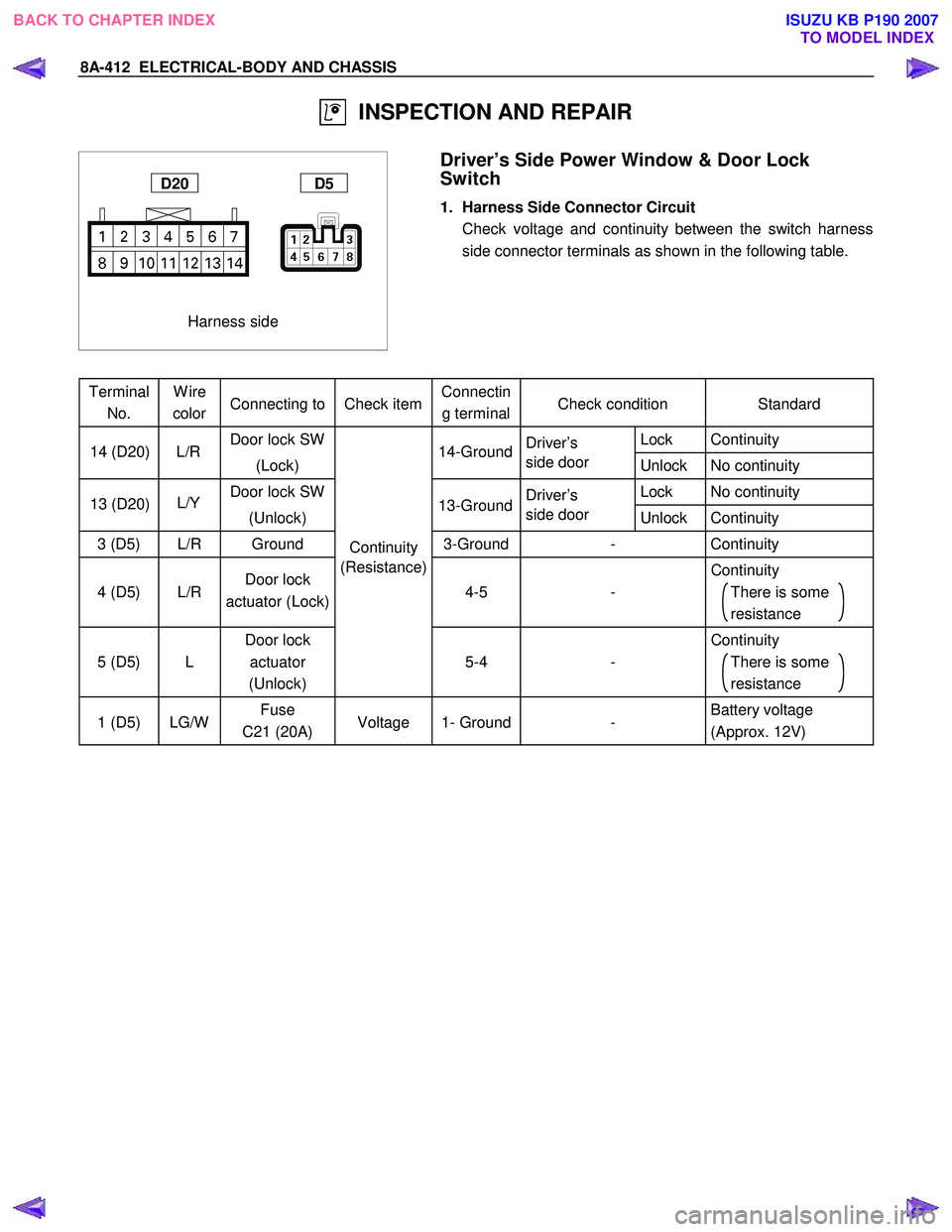
Driver’s Side Power Window & Door Lock
Switch
1. Harness Side Connector Circuit
Check voltage and continuity between the switch harness side connector terminals as shown in the following table.
Terminal No. Wire
color Connecting to Check item Connectin
g terminal Check condition
Standard
Door lock SW
Driver’s Lock Continuity
(Lock) side door
Unlock No continuity
Door lock SW
Driver’s Lock No continuity
(Unlock) side door
Unlock Continuity
3 (D5) L/R Ground Continuity 3-Ground
- Continuity
4 (D5)
L/R Door lock
actuator (Lock) (Resistance)
4-5
- Continuity
There is some
resistance
5 (D5)
L Door lock
actuator
(Unlock)
5-4
- Continuity
There is some
resistance
1 (D5) LG/W Fuse
C21 (20A) Voltage 1- Ground
- Battery voltage
(Approx. 12V)
14-Ground
L/R
14 (D20)
13-Ground
L/Y
13 (D20)
BACK TO CHAPTER INDEX
TO MODEL INDEXISUZU KB P190 2007
Page 5372 of 6020
8A-434 ELECTRICAL-BODY AND CHASSIS
INSPECTION AND REPAIR
B8
RTW 78ASH002901
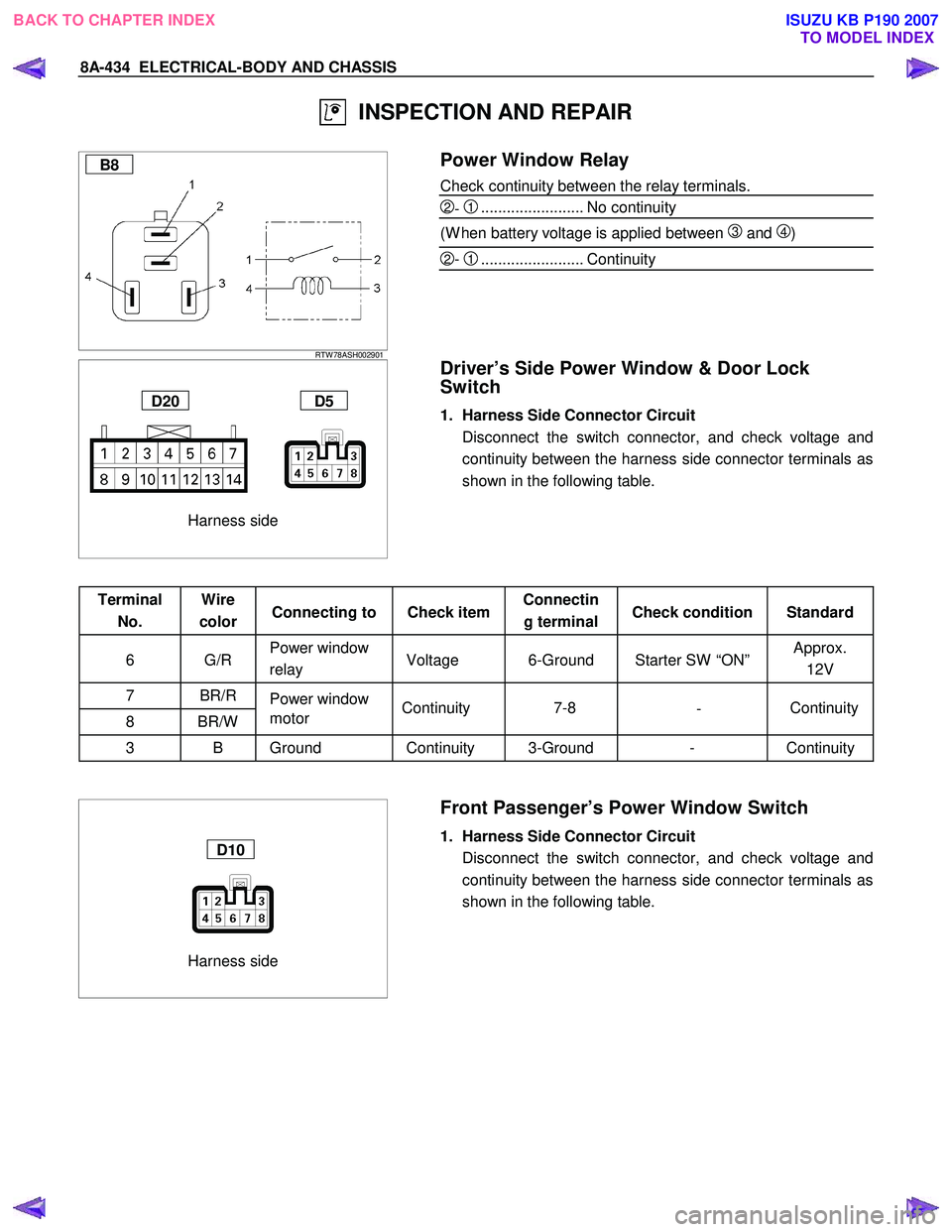
Power Window Relay
Check continuity between the relay terminals.
2- 1........................ No continuity
(W hen battery voltage is applied between
3 and 4)
2- 1........................ Continuity
Harness side
D20 D5
Driver’s Side Power Window & Door Lock
Switch
1. Harness Side Connector Circuit
Disconnect the switch connector, and check voltage and continuity between the harness side connector terminals as
shown in the following table.
Terminal No. Wire
color Connecting to Check item Connectin
g terminal Check condition Standard
6 G/R Power window
relay Voltage 6-Ground Starter SW “ON” Approx.
12V
7 BR/R Power window
8 BR/W motor
3 B Ground Continuity 3-Ground - Continuity
Harness side
D10
Front Passenger’s Power Window Switch
1. Harness Side Connector Circuit
Disconnect the switch connector, and check voltage and continuity between the harness side connector terminals as
shown in the following table.
Continuity
-
7-8
Continuity
BACK TO CHAPTER INDEX
TO MODEL INDEXISUZU KB P190 2007
Page 5373 of 6020

ELECTRICAL-BODY AND CHASSIS 8A-435
Terminal No. Wire
color Connecting to Check item Connectin
g terminal Check condition Standard
6 G/R Power window
relay Voltage 6-Ground Starter SW “ON” Approx.
12V
8 BR/R
7 BR/W Power window
motor Continuity 8-7
- Continuity
1,3 B Ground Continuity 1,3-Ground - Continuity
Harness side
D12 D16
Rear Power Window Switch-LH & RH
1. Harness Side Connector Circuit
Disconnect the switch connector, and check voltage and continuity between the harness side connector terminals as
shown in the following tables.
D12 (RR-LH)
Terminal No. Wire
color Connecting to Check item Connectin
g terminal Check condition Standard
6 G/R Power window
relay Voltage 6-Ground Starter SW “ON” Approx.
12V
8 BR/R
7 BR/W Power window
motor Continuity 8-7
- Continuity
3 B
4 B Ground Continuity 3,4-Ground - Continuity
D16 (RR-RH)
Terminal
No. Wire
color Connecting to Check item Connectin
g terminal Check condition Standard
6 G/R Power window
relay Voltage 6-Ground Starter SW “ON” Approx.
12V
8 BR/R
7 BR/W Power window
motor Continuity 8-7
- Continuity
3 B Ground Continuity 3-Ground - Continuity
BACK TO CHAPTER INDEX
TO MODEL INDEXISUZU KB P190 2007
Page 5374 of 6020
8A-436 ELECTRICAL-BODY AND CHASSIS
Harness side
D5
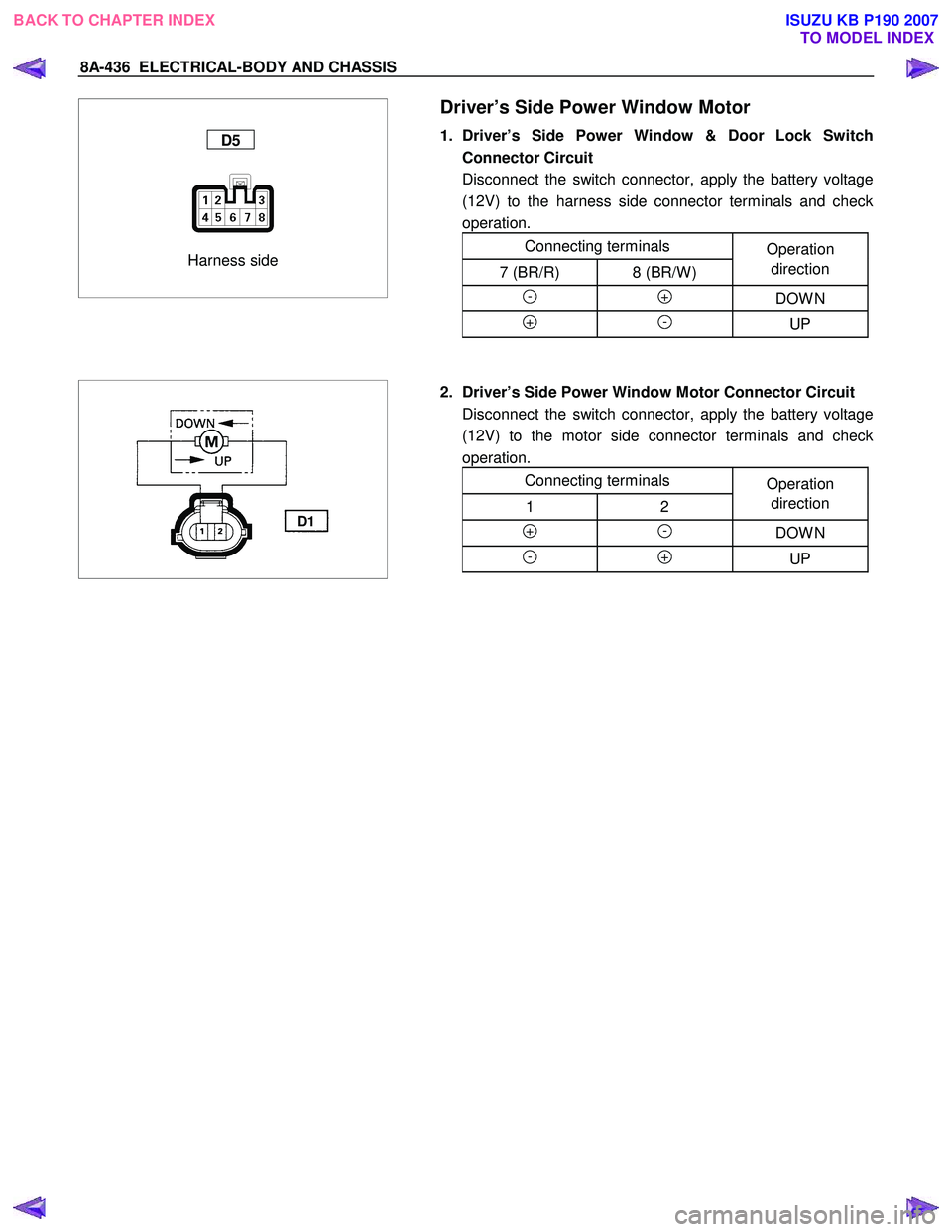
Driver’s Side Power Window Motor
1. Driver’s Side Power Window & Door Lock Switch
Connector Circuit
Disconnect the switch connector, apply the battery voltage (12V) to the harness side connector terminals and check
operation.
Connecting terminals Operation
7 (BR/R) 8 (BR/W ) direction
- + DOW N
+ - UP
D1
2. Driver’s Side Power Window Motor Connector Circuit
Disconnect the switch connector, apply the battery voltage (12V) to the motor side connector terminals and check
operation.
Connecting terminals Operation
1 2 direction
+ - DOW N
- + UP
BACK TO CHAPTER INDEX
TO MODEL INDEXISUZU KB P190 2007
Page 5375 of 6020

ELECTRICAL-BODY AND CHASSIS 8A-437
Harness side
D10
Front Passenger’s Power Window Motor
1. Front Passenger’s Power Window Switch Connector
Circuit
Disconnect the motor connector, apply the battery voltage (12V) to the harness side connector terminals and check
operation.
Connecting terminals Operation
8 (BR/R) 7 (BR/W ) direction
- + DOW N
+ - UP
D6
2. Front Passenger’s Power Window Motor Connector
Circuit
Disconnect the switch connector, apply the battery voltage (12V) to the motor side connector terminals and check
operation.
Connecting terminals Operation
1 2 direction
+ - DOW N
- + UP
BACK TO CHAPTER INDEX
TO MODEL INDEXISUZU KB P190 2007
Page 5376 of 6020

8A-438 ELECTRICAL-BODY AND CHASSIS
Harness side
D12
Rear Passenger’s Power Window Motor-LH
1. Rear Power Window Switch-LH Connector Circuit
Disconnect the motor connector, apply the battery voltage (12V) to the harness side connector terminals and check
operation.
Connecting terminals Operation
8 (BR/R) 7 (BR/W ) direction
- + DOW N
+ - UP
D11
2. Rear Power Window Motor-LH Connector Circuit
Disconnect the switch connector, apply the battery voltage (12V) to the motor side connector terminals and check
operation.
Connecting terminals Operation
1 2 direction
+ - DOW N
- + UP
BACK TO CHAPTER INDEX
TO MODEL INDEXISUZU KB P190 2007
Page 5377 of 6020

ELECTRICAL-BODY AND CHASSIS 8A-439
Harness side
D16
Rear Power Window Motor-RH
1. Rear Power Window Switch-RH Connector Circuit
Disconnect the motor connector, apply the battery voltage (12V) to the harness side connector terminals and check
operation.
Connecting terminals Operation
8 (BR/R) 7 (BR/W ) direction
- + DOW N
+ - UP
D15
2. Rear Power Window Motor-RH Connector Circuit
Disconnect the switch connector, apply the battery voltage (12V) to the motor side connector terminals and check
operation.
Connecting terminals Operation
1 2 direction
+ - DOW N
- + UP
BACK TO CHAPTER INDEX TO MODEL INDEXISUZU KB P190 2007
Page 5416 of 6020

8A-478 ELECTRICAL-BODY AND CHASSIS
• W hen there is no continuity at either one of the circuit
No, 5, 7, 8, or 10, the motor in the mirror of the circuit o
r
the circuit itself is defective.
Terminal No. Wire
color Connection to Check item
Connecting
terminal Check condition Standard
7 W /B
LH mirror & RH
mirror Continuity 7-Ground - No continuity
4 R/Y Fuse C11 (10A) Voltage 4-Ground
Starter SW “ACC”
position Approx.
12V
10 W /R RH mirror-LH/RH 10-7 -
2 B/W RH mirror-Up/Down 2-7 -
3 B/R LH mirror-Up/Down Continuity 3-7 - Continuity
8 B Ground 8-Ground -
9 W /G LH mirror-LH/RH 9-7 -
Harness side
D19
Door Mirror
1. Door Mirror Control Switch Connector Circuit
Disconnect the switch connector
D19 , apply the battery
voltage to the harness side connector terminals and check
its function.
Connector
No. D19
Operating
Terminal
Mirror No. 9 10 7 3 2direction
+ - Left
- + Right
- +Up
+ -Down
+ - Left
- + Right
- + Up
+ - Down
Left
Right
BACK TO CHAPTER INDEX
TO MODEL INDEXISUZU KB P190 2007
Page 5519 of 6020
ELECTRICAL-BODY AND CHASSIS 8A-581
060RW 009
Tech-2 Features
1. Tech-2 is a 12volt system. Do not apply 24 volts.
2.
After connecting and/or installing the vehicle
communication interface (VCI) module, PCMCI
A
card and data link connector (DLC) to the Tech-
2, connect the tool to the vehicle DLC.
3. Make sure the Tech-2 is OFF when removing o
r
installing the PCMCIA card.
4. The Tech-2 has the capability of two snapshot.
5. The PCMCIA card is sensitive to magnetism and
static electricity, so care should be taken in the
handling of the card.
6. The Tech-2 can not plot a graph when replaying
a snapshot.
7.
Always return to the Main Menu by pressing the
EXIT key several times before shutting down.
8. To clear diagnostic trouble codes (DTCs), open
Application Menu and press "Clear DTC ".
060R300015
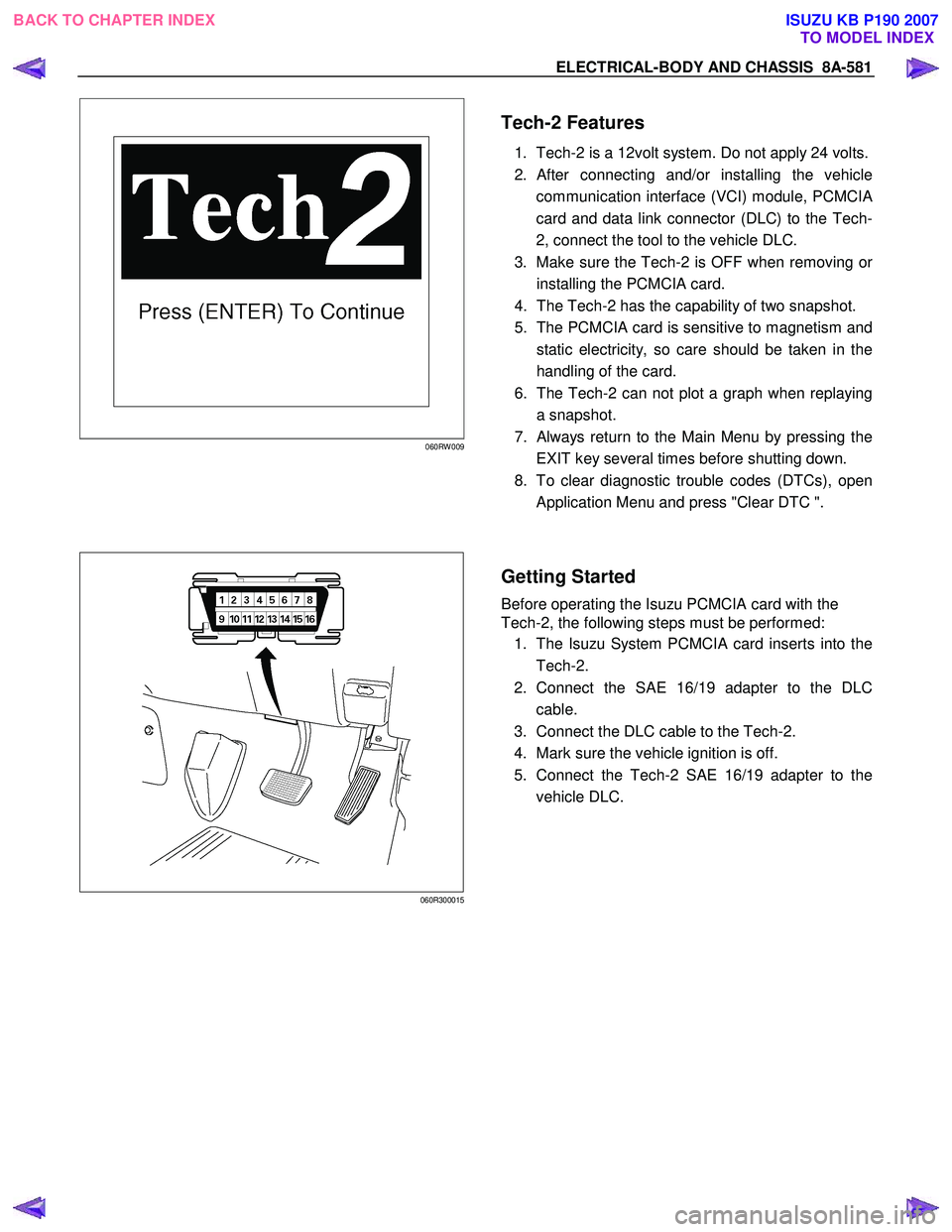
Getting Started
Before operating the Isuzu PCMCIA card with the
Tech-2, the following steps must be performed:
1. The Isuzu System PCMCIA card inserts into the
Tech-2.
2. Connect the SAE 16/19 adapter to the DLC
cable.
3. Connect the DLC cable to the Tech-2.
4. Mark sure the vehicle ignition is off.
5. Connect the Tech-2 SAE 16/19 adapter to the
vehicle DLC.
BACK TO CHAPTER INDEX TO MODEL INDEXISUZU KB P190 2007
Page 5924 of 6020

11A-26 IMMOBILIZER SYSTEM (C24SE, 4JA1-T)
Data List
No.
No.No.
No.
Strings
StringsStrings
Strings
Note
NoteNote
Note
1 Ignition Status
On 12V /Off 0V
2 Transponder-Key Transp. Key #
The number of the key currently
programmed
3 Transponder Status Correct/Incorrect TP-Key
4 Transponder-Key 1 Status Programmed / Not Programmed
5 Transponder-Key 2 Status Programmed / Not Programmed
6 Transponder-Key 3 Status Programmed / Not Programmed
7 Transponder-Key 4 Status Programmed / Not Programmed
8 Transponder-Key 5 Status Programmed / Not Programmed
9
Immobilizer signal Transmitted / Not Transmitted
10 Engine Request Received / Not Received
11 Vehicle Speed Output Veh.
Speed signal
12 Immobilizer Relay
Active 0V / Inactive 12V
13 Security Wait Time
Active / Inactive
BACK TO CHAPTER INDEX TO MODEL INDEX
ISUZU KB P190 2007