vacuum ISUZU KB P190 2007 Workshop Owners Manual
[x] Cancel search | Manufacturer: ISUZU, Model Year: 2007, Model line: KB P190, Model: ISUZU KB P190 2007Pages: 6020, PDF Size: 70.23 MB
Page 1315 of 6020
Engine Control System (4JH1) 6E-281
Installation Procedure
1. Install the MAF & IAT sensor assembly into intake air duct.
2. Tighten the clips.
3. Connect a MAF & IAT sensor connector to the MAF & IAT sensor assembly.
4. Connect the negative battery cable.
Turbocharger Solenoid Valve Replacement
[High Altitude Spec]
Removal Procedure
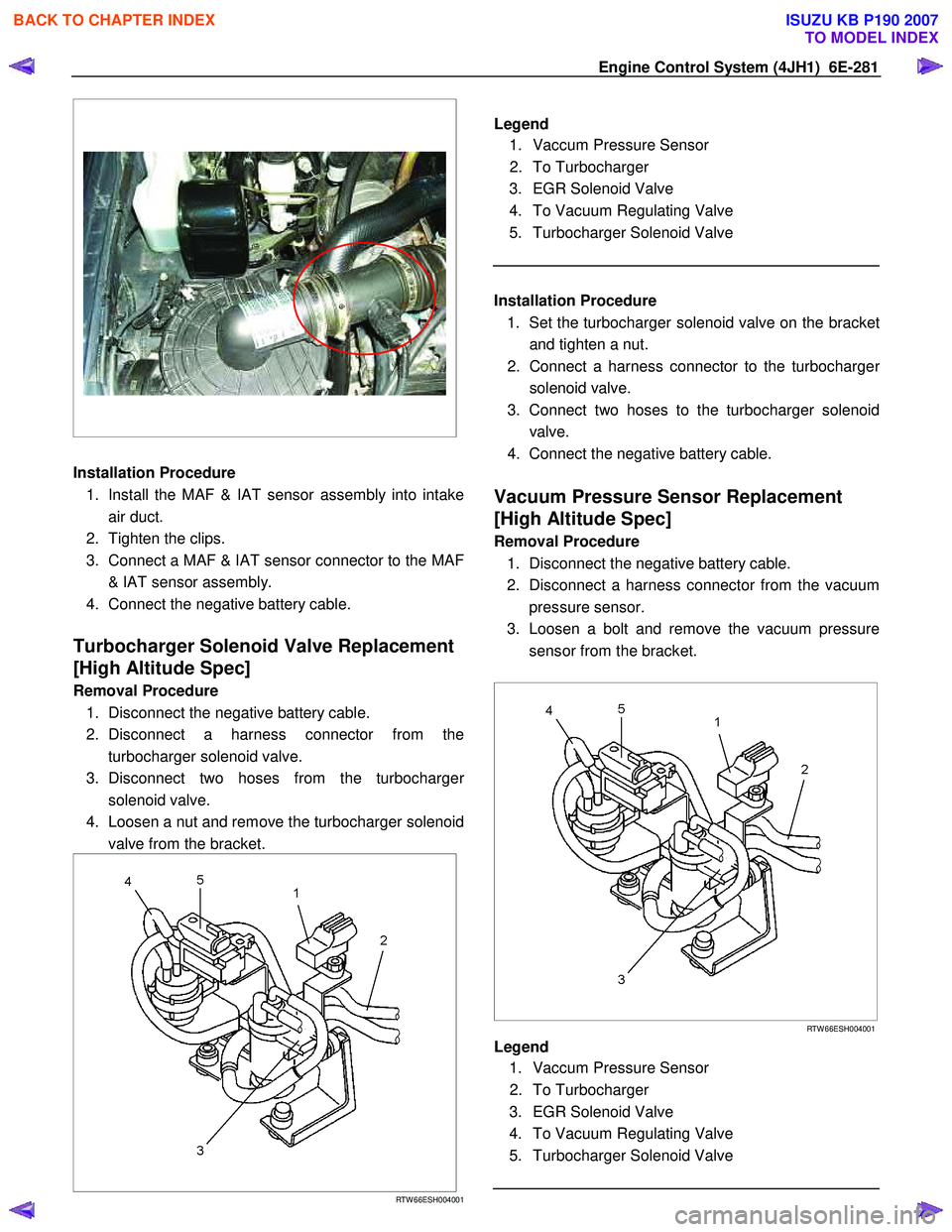
1. Disconnect the negative battery cable.
2. Disconnect a harness connector from the turbocharger solenoid valve.
3. Disconnect two hoses from the turbocharge
r
solenoid valve.
4. Loosen a nut and remove the turbocharger solenoid valve from the bracket.
RTW 66ESH004001
Legend
1. Vaccum Pressure Sensor
2. To Turbocharger
3. EGR Solenoid Valve
4. To Vacuum Regulating Valve
5. Turbocharger Solenoid Valve
Installation Procedure
1. Set the turbocharger solenoid valve on the bracke
t
and tighten a nut.
2. Connect a harness connector to the turbocharge
r
solenoid valve.
3. Connect two hoses to the turbocharger solenoid valve.
4. Connect the negative battery cable.
Vacuum Pressure Sensor Replacement
[High Altitude Spec]
Removal Procedure
1. Disconnect the negative battery cable.
2. Disconnect a harness connector from the vacuum pressure sensor.
3. Loosen a bolt and remove the vacuum pressure sensor from the bracket.
RTW 66ESH004001
Legend
1. Vaccum Pressure Sensor
2. To Turbocharger
3. EGR Solenoid Valve
4. To Vacuum Regulating Valve
5. Turbocharger Solenoid Valve
BACK TO CHAPTER INDEX
TO MODEL INDEX
ISUZU KB P190 2007
Page 1316 of 6020
6E-282 Engine Control System (4JH1)
Installation Procedure 1. Set the vacuum pressure sensor on the bracket and tighten a bolt.
2. Connect a harness connector to the vacuum pressure sensor.
3. Connect the negative battery cable.
Vehicle Speed Sensor (VSS) Replacement
Removal Procedure
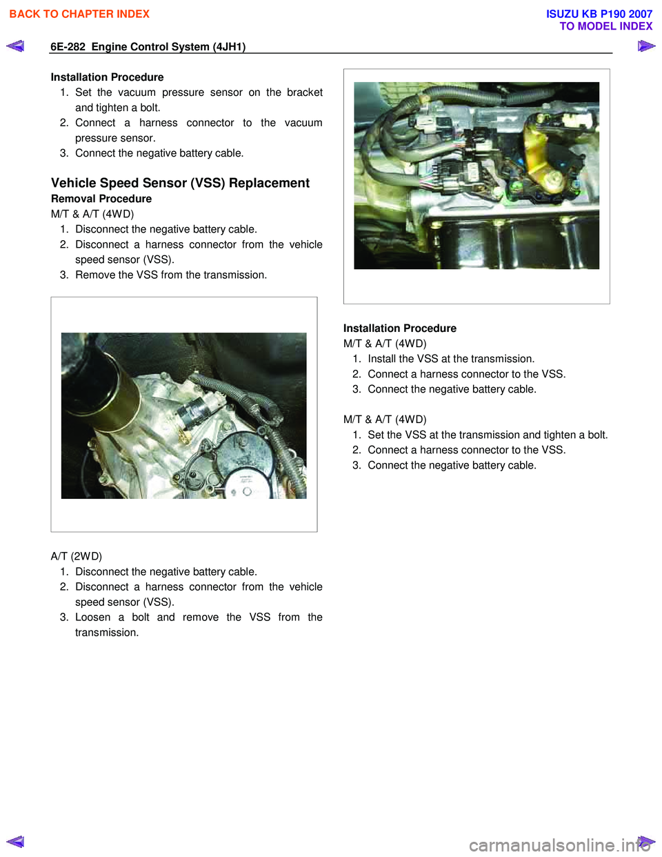
M/T & A/T (4W D) 1. Disconnect the negative battery cable.
2. Disconnect a harness connector from the vehicle speed sensor (VSS).
3. Remove the VSS from the transmission.
A/T (2W D)
1. Disconnect the negative battery cable.
2. Disconnect a harness connector from the vehicle speed sensor (VSS).
3. Loosen a bolt and remove the VSS from the transmission.
Installation Procedure
M/T & A/T (4W D) 1. Install the VSS at the transmission.
2. Connect a harness connector to the VSS.
3. Connect the negative battery cable.
M/T & A/T (4W D) 1. Set the VSS at the transmission and tighten a bolt.
2. Connect a harness connector to the VSS.
3. Connect the negative battery cable.
BACK TO CHAPTER INDEX
TO MODEL INDEX
ISUZU KB P190 2007
Page 1317 of 6020
Engine Control System (4JH1) 6E-283
Description And Operation
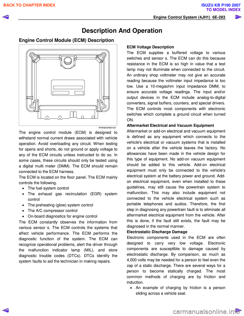
Engine Control Module (ECM) Description
RTW 66ESH001201
The engine control module (ECM) is designed to
withstand normal current draws associated with vehicle
operation. Avoid overloading any circuit. W hen testing
for opens and shorts, do not ground or apply voltage to
any of the ECM circuits unless instructed to do so. In
some cases, these circuits should only be tested using
a digital multi meter (DMM). The ECM should remain
connected to the ECM harness.
The ECM is located on the floor panel. The ECM mainl
y
controls the following.
• The fuel system control
• The exhaust gas recirculation (EGR) system
control
• The preheating (glow) system control
• The A/C compressor control
• On-board diagnostics for engine control
The ECM constantly observes the information from
various sensor s. The ECM controls the systems that
affect vehicle performance. The ECM performs the
diagnostic function of the system. The ECM can
recognize operational problems, alert the driver through
the malfunction indicator lamp (MIL), and store
diagnostic trouble codes (DTCs). DTCs identify the
system faults to aid the technician in making repairs.
ECM Voltage Description
The ECM supplies a buffered voltage to various
switches and sensor s. The ECM can do this because
resistance in the ECM is so high in value that a test
lamp may not illuminate when connected to the circuit.
An ordinary shop voltmeter may not give an accurate
reading because the voltmeter input impedance is too
low. Use a 10-megaohm input impedance DMM, to
ensure accurate voltage readings. The input and/o
r
output devices in the ECM include analog-to-digital
converters, signal buffers, counters, and special drivers.
The ECM controls most components with electronic
switches which complete a ground circuit when turned
ON.
Aftermarket Electrical and Vacuum Equipment
Aftermarket or add-on electrical and vacuum equipment
is defined as any equipment which connects to the
vehicle's electrical or vacuum systems that is installed
on a vehicle after the vehicle leaves the factory. No
allowances have been made in the vehicle design fo
r
this type of equipment. No add-on vacuum equipment
should be added to this vehicle. Add-on electrical
equipment must only be connected to the vehicle's
electrical system at the battery power and ground. Add-
on electrical equipment, even when installed to these
guidelines, may still cause the powertrain system to
malfunction. This may also include equipment not
connected to the vehicle electrical system such as
portable telephones and audios. Therefore, the first
step in diagnosing any powertrain fault is to eliminate all
aftermarket electrical equipment from the vehicle. Afte
r
this is done, if the fault still exists, the fault may be
diagnosed in the normal manner.
Electrostatic Discharge Damage
Electronic components used in the ECM are often
designed to carry very low voltage. Electronic
components are susceptible to damage caused b
y
electrostatic discharge. By comparison, as much as
4,000 volts may be needed for a person to feel even the
zap of a static discharge. There are several ways for a
person to become statically charged. The most
common methods of charging are by friction and
induction. •
An example of charging by friction is a person
sliding across a vehicle seat.
BACK TO CHAPTER INDEX
TO MODEL INDEX
ISUZU KB P190 2007
Page 1331 of 6020
Engine Control System (4JH1) 6E-297
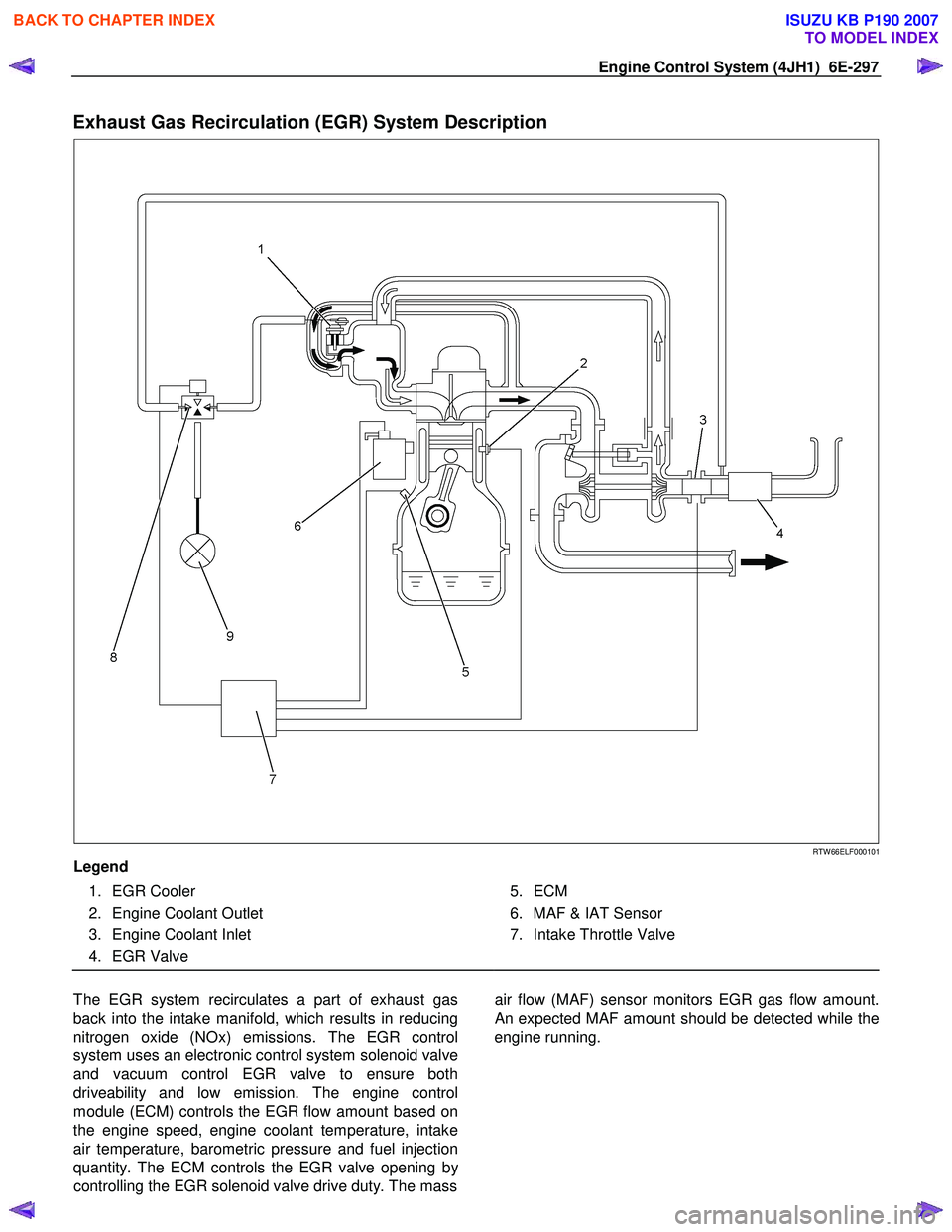
Exhaust Gas Recirculation (EGR) System Description
RTW 66ELF000101
Legend
1. EGR Cooler
2. Engine Coolant Outlet
3. Engine Coolant Inlet
4. EGR Valve
5. ECM
6. MAF & IAT Sensor
7. Intake Throttle Valve
The EGR system recirculates a part of exhaust gas
back into the intake manifold, which results in reducing
nitrogen oxide (NOx) emissions. The EGR control
system uses an electronic control system solenoid valve
and vacuum control EGR valve to ensure both
driveability and low emission. The engine control
module (ECM) controls the EGR flow amount based on
the engine speed, engine coolant temperature, intake
air temperature, barometric pressure and fuel injection
quantity. The ECM controls the EGR valve opening b
y
controlling the EGR solenoid valve drive duty. The mass
air flow (MAF) sensor monitors EGR gas flow amount.
An expected MAF amount should be detected while the
engine running.
BACK TO CHAPTER INDEX
TO MODEL INDEX
ISUZU KB P190 2007
Page 1332 of 6020
6E-298 Engine Control System (4JH1)
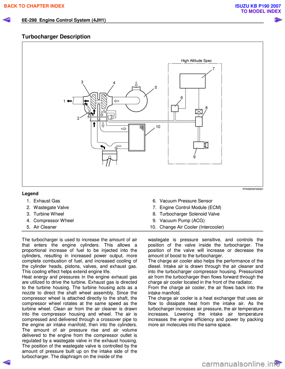
Turbocharger Description
RTW 66EMF000501
Legend
1. Exhaust Gas
2. W astegate Valve
3. Turbine W heel
4. Compressor W heel
5. Air Cleaner
6. Vacuum Pressure Sensor
7. Engine Control Module (ECM)
8. Turbocharger Solenoid Valve
9. Vacuum Pump (ACG)
10. Change Air Cooler (Intercooler)
The turbocharger is used to increase the amount of ai
r
that enters the engine cylinders. This allows a
proportional increase of fuel to be injected into the
cylinders, resulting in increased power output, more
complete combustion of fuel, and increased cooling o
f
the cylinder heads, pistons, valves, and exhaust gas.
This cooling effect helps extend engine life.
Heat energy and pressures in the engine exhaust gas
are utilized to drive the turbine. Exhaust gas is directed
to the turbine housing. The turbine housing acts as a
nozzle to direct the shaft wheel assembly. Since the
compressor wheel is attached directly to the shaft, the
compressor wheel rotates at the same speed as the
turbine wheel. Clean air from the air cleaner is drawn
into the compressor housing and wheel. The air is
compressed and delivered through a crossover pipe to
the engine air intake manifold, then into the cylinders.
The amount of air pressure rise and air volume
delivered to the engine from the compressor outlet is
regulated by a wastegate valve in the exhaust housing.
The position of the wastegate valve is controlled by the
amount of pressure built up on the intake side of the
turbocharger. The diaphragm on the inside of the
wastegate is pressure sensitive, and controls the
position of the valve inside the turbocharger. The
position of the valve will increase or decrease the
amount of boost to the turbocharger.
The charge air cooler also helps the performance of the
diesel. Intake air is drawn through the air cleaner and
into the turbocharger compressor housing. Pressurized
air from the turbocharger then flows forward through the
charge air cooler located in the front of the radiator.
From the charge air cooler, the air flows back into the
intake manifold.
The charge air cooler is a heat exchanger that uses ai
r
flow to dissipate heat from the intake air. As the
turbocharger increases air pressure, the air temperature
increases. Lowering the intake air temperature
increases the engine efficiency and power by packing
more air molecules into the same space.
BACK TO CHAPTER INDEX
TO MODEL INDEX
ISUZU KB P190 2007
Page 1333 of 6020
Engine Control System (4JH1) 6E-299
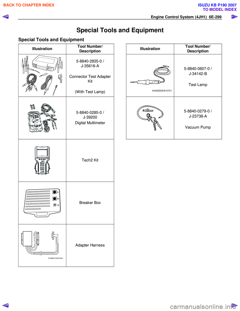
Special Tools and Equipment
Special Tools and Equipment
Illustration Tool Number/
Description
Illustration Tool Number/
Description
5-8840-2835-0 /
J-35616-A
Connector Test Adapter Kit
(W ith Test Lamp)
5-8840-0607-0 /
J-34142-B
Test Lamp
5-8840-0285-0 /
J-39200
Digital Multimeter
5-8840-0279-0 /
J-23738-A
Vacuum Pump
Tech2 Kit
Breaker Box
Adapter Harness
BACK TO CHAPTER INDEX
TO MODEL INDEX
ISUZU KB P190 2007
Page 1340 of 6020
EXHAUST SYSTEM 6F – 7
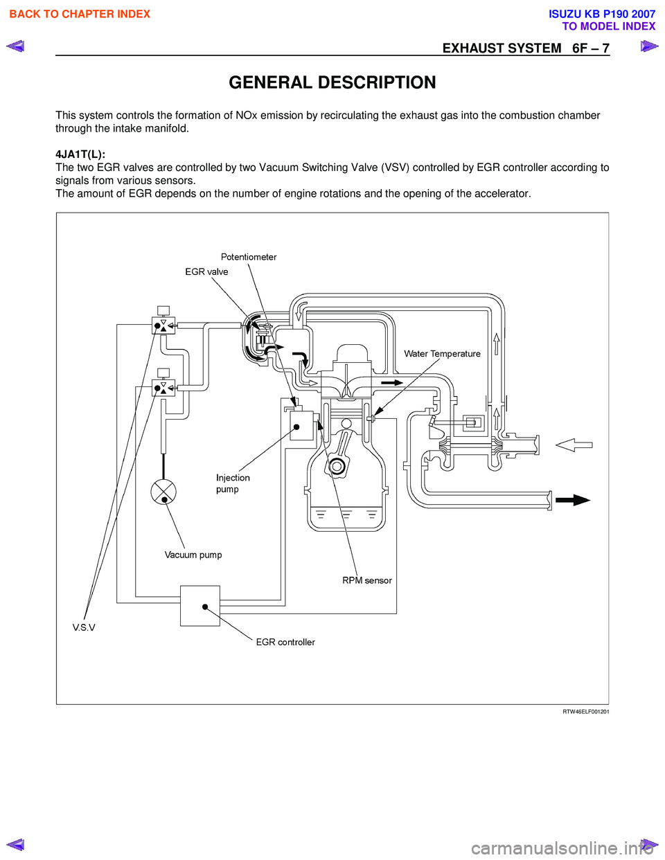
GENERAL DESCRIPTION
This system controls the formation of NOx emission by recirculating the exhaust gas into the combustion chamber
through the intake manifold.
4JA1T(L):
The two EGR valves are controlled by two Vacuum Switching Valve (VSV) controlled by EGR controller according to
signals from various sensors.
The amount of EGR depends on the number of engine rotations and the opening of the accelerator.
RTW 46ELF001201
BACK TO CHAPTER INDEX
TO MODEL INDEX
ISUZU KB P190 2007
Page 1344 of 6020
EXHAUST SYSTEM 6F – 11
INSPECTION
4JA1T(L)
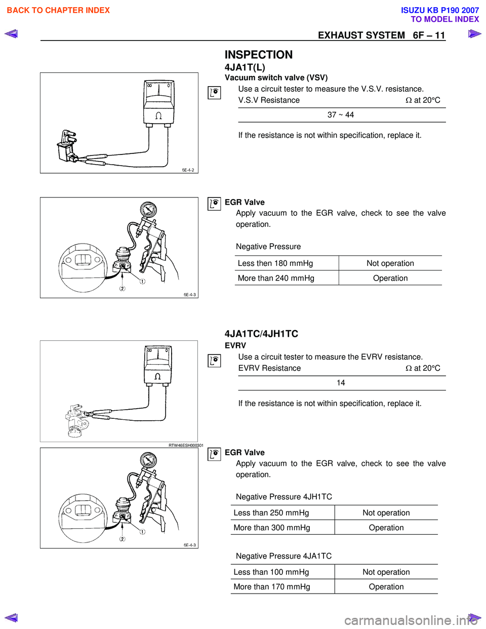
Vacuum switch valve (VSV)
Use a circuit tester to measure the V.S.V. resistance.
V.S.V Resistance Ω at 20°C
37 ~ 44
If the resistance is not within specification, replace it.
EGR Valve
Apply vacuum to the EGR valve, check to see the valve
operation.
Negative Pressure
4JA1TC/4JH1TC
RTW 46ESH000301
EVRV
Use a circuit tester to measure the EVRV resistance.
EVRV Resistance Ω at 20°C
14
If the resistance is not within specification, replace it.
EGR Valve
Apply vacuum to the EGR valve, check to see the valve
operation.
Negative Pressure 4JH1TC
Less than 250 mmHg Not operation
More than 300 mmHg Operation
Negative Pressure 4JA1TC
Less than 100 mmHg Not operation
More than 170 mmHg Operation
Less then 180 mmHg Not operation
More than 240 mmHg
Operation
BACK TO CHAPTER INDEX
TO MODEL INDEX
ISUZU KB P190 2007
Page 1376 of 6020
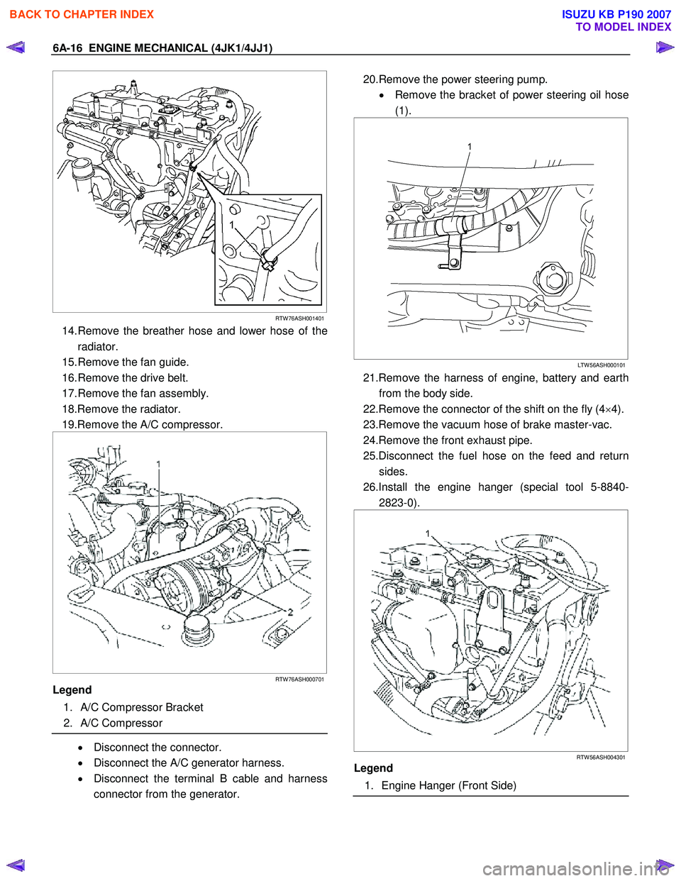
6A-16 ENGINE MECHANICAL (4JK1/4JJ1)
RTW 76ASH001401
14. Remove the breather hose and lower hose of the
radiator.
15. Remove the fan guide.
16. Remove the drive belt.
17. Remove the fan assembly.
18.Remove the radiator.
19.Remove the A/C compressor.
RTW 76ASH000701
Legend
1. A/C Compressor Bracket
2. A/C Compressor
• Disconnect the connector.
• Disconnect the A/C generator harness.
• Disconnect the terminal B cable and harness
connector from the generator.
20.Remove the power steering pump.
• Remove the bracket of power steering oil hose
(1).
LTW 56ASH000101
21.Remove the harness of engine, battery and earth
from the body side.
22.Remove the connector of the shift on the fly (4 ×4).
23.Remove the vacuum hose of brake master-vac.
24.Remove the front exhaust pipe.
25.Disconnect the fuel hose on the feed and return sides.
26.Install the engine hanger (special tool 5-8840- 2823-0).
RTW 56ASH004301
Legend
1. Engine Hanger (Front Side)
BACK TO CHAPTER INDEX
TO MODEL INDEX
ISUZU KB P190 2007
Page 1377 of 6020
ENGINE MECHANICAL (4JK1/4JJ1) 6A-17
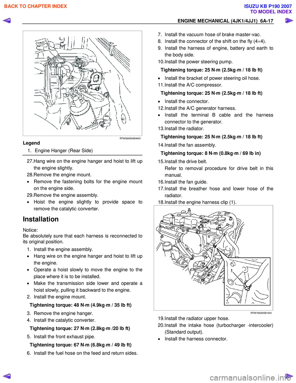
RTW 56ASH004401
Legend
1. Engine Hanger (Rear Side)
27.Hang wire on the engine hanger and hoist to lift up
the engine slightly.
28.Remove the engine mount.
• Remove the fastening bolts for the engine mount
on the engine side.
29.Remove the engine assembly.
• Hoist the engine slightly to provide space to
remove the catalytic converter.
Installation
Notice:
Be absolutely sure that each harness is reconnected to
its original position.
1. Install the engine assembly.
• Hang wire on the engine hanger and hoist to lift up
the engine.
• Operate a hoist slowly to move the engine to the
place where it is to be installed.
• Make the transmission side lower and operate a
hoist slowly, pulling it backward to the engine.
2. Install the engine mount.
Tightening torque: 48 N ⋅
⋅⋅
⋅
m (4.9kg ⋅
⋅⋅
⋅
m / 35 lb ft)
3. Remove the engine hanger.
4. Install the catalytic converter.
Tightening torque: 27 N ⋅
⋅⋅
⋅
m (2.8kg ⋅
⋅⋅
⋅
m /20 lb ft)
5. Install the front exhaust pipe. Tightening torque: 67 N ⋅
⋅⋅
⋅
m (6.8kg ⋅
⋅⋅
⋅
m / 49 lb ft)
6. Install the fuel hose on the feed and return sides.
7. Install the vacuum hose of brake master-vac.
8. Install the connector of the shift on the fly (4 ×4).
9. Install the harness of engine, battery and earth to the body side.
10.Install the power steering pump.
Tightening torque: 25 N ⋅
⋅⋅
⋅
m (2.5kg ⋅
⋅⋅
⋅
m / 18 lb ft)
• Install the bracket of power steering oil hose.
11.Install the A/C compressor.
Tightening torque: 25 N ⋅
⋅⋅
⋅
m (2.5kg ⋅
⋅⋅
⋅
m / 18 lb ft)
• Install the connector.
12.Install the A/C generator harness.
• Install the terminal B cable and the harness
connector to the generator.
13.Install the radiator.
Tightening torque: 25 N ⋅
⋅⋅
⋅
m (2.5kg ⋅
⋅⋅
⋅
m / 18 lb ft)
14.Install the fan assembly. Tightening torque: 8 N ⋅
⋅⋅
⋅
m (0.8kg ⋅
⋅⋅
⋅
m / 69 lb in)
15.Install the drive belt.
Refer to removal procedure for drive belt in this manual.
16.Install the fan guide.
17.Install the breather hose and lower hose of the radiator.
18.Install the engine harness clip (1).
RTW 76ASH001401
19.Install the radiator upper hose.
20.Install the intake hose (turbocharger -intercooler) (Standard output).
• Install the harness connector.
BACK TO CHAPTER INDEX
TO MODEL INDEX
ISUZU KB P190 2007