vacuum ISUZU KB P190 2007 Workshop Workshop Manual
[x] Cancel search | Manufacturer: ISUZU, Model Year: 2007, Model line: KB P190, Model: ISUZU KB P190 2007Pages: 6020, PDF Size: 70.23 MB
Page 1074 of 6020
6E-40 Engine Control System (4JH1)
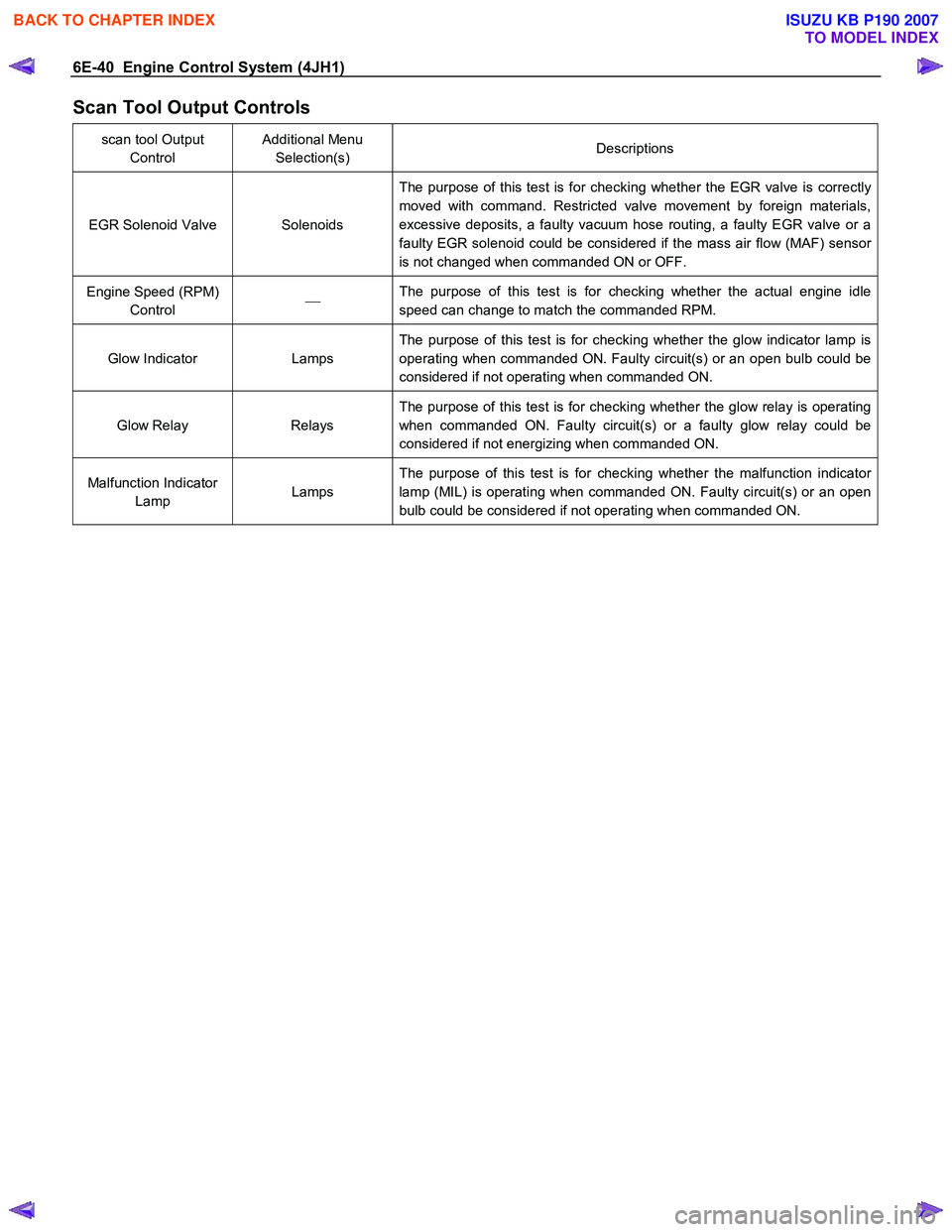
Scan Tool Output Controls
scan tool Output Control Additional Menu
Selection(s) Descriptions
EGR Solenoid Valve Solenoids The purpose of this test is for checking whether the EGR valve is correctly
moved with command. Restricted valve movement by foreign materials,
excessive deposits, a faulty vacuum hose routing, a faulty EGR valve or a
faulty EGR solenoid could be considered if the mass air flow (MAF) sensor
is not changed when commanded ON or OFF.
Engine Speed (RPM) Control
The purpose of this test is for checking whether the actual engine idle
speed can change to match the commanded RPM.
Glow Indicator Lamps The purpose of this test is for checking whether the glow indicator lamp is
operating when commanded ON. Faulty circuit(s) or an open bulb could be
considered if not operating when commanded ON.
Glow Relay Relays The purpose of this test is for checking whether the glow relay is operating
when commanded ON. Faulty circuit(s) or a faulty glow relay could be
considered if not energizing when commanded ON.
Malfunction Indicator Lamp Lamps The purpose of this test is for checking whether the malfunction indicator
lamp (MIL) is operating when commanded ON. Faulty circuit(s) or an open
bulb could be considered if not operating when commanded ON.
BACK TO CHAPTER INDEX
TO MODEL INDEX
ISUZU KB P190 2007
Page 1083 of 6020
Engine Control System (4JH1) 6E-49
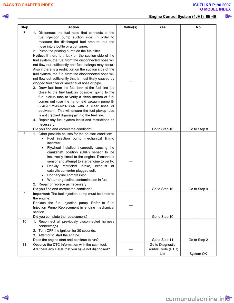
Step Action Value(s) Yes No
7 1. Disconnect the fuel hose that connects to the
fuel injection pump suction side. In order to
measure the discharged fuel amount, put the
hose into a bottle or a container.
2. Pump the priming pump on the fuel filter.
Notice: If there is a leak on the suction side of the
fuel system, the fuel from the disconnected hose will
not flow out sufficiently and fuel leakage may occur.
Also if there is a restriction on the suction side of the
fuel system, the fuel from the disconnected hose will
not flow out sufficiently that is most likely caused by
clogged fuel filter or kinked fuel hose or pipe.
3. Draw fuel from the fuel tank at the fuel line (as close to the fuel tank as possible) going to the
fuel pickup tube to verify a clean stream of fuel
comes out (use the hand-held vacuum pump 5-
8840-0279-0/J-23738-A with a clear hose or
equivalent). This will ensure the fuel pickup tube
is not cracked drawing air into the fuel line.
4. Repair any fuel system leaks and restrictions as necessary.
Did you find and correct the condition?
Go to Step 10 Go to Step 8
8 1. Other possible causes for the no-start condition: • Fuel injection pump mechanical timing
incorrect
• Flywheel installed incorrectly causing the
crankshaft position (CKP) sensor to be
incorrectly timed to the engine. Disconnect
sensor and attempt to start engine to verify.
• Heavily restricted intake, exhaust or
catalytic converter plugged solid
• Poor engine compression
• W ater or gasoline contamination in fuel
2. Repair or replace as necessary.
Did you find and correct the condition?
Go to Step 10 Go to Step 9
9 Important: The fuel injection pump must be timed to
the engine.
Replace the fuel injection pump. Refer to Fuel
Injection Pump Replacement in engine mechanical
section.
Did you complete the replacement?
Go to Step 10
10 1. Reconnect all previously disconnected harness
connector(s).
2. Turn OFF the ignition for 30 seconds.
3. Attempt to start the engine.
Does the engine start and continue to run?
Go to Step 11 Go to Step 2
11 Observe the DTC Information with the scan tool. Are there any DTCs that you have not diagnosed? Go to Diagnostic
Trouble Code (DTC) List System OK
BACK TO CHAPTER INDEX
TO MODEL INDEX
ISUZU KB P190 2007
Page 1084 of 6020

6E-50 Engine Control System (4JH1)
Diagnostic Trouble Code (DTC) List
DTC
(Symptom Code) Flash
Code MIL
Status DTC Name on
scan tool Condition for
Running the DTC Condition for
Setting the DTC Possible Cause
P0100
(7) 65 ON Mass Air Flow
(MAF) Sensor
Circuit 5V
Reference High
Voltage •
The ignition switch
is ON.
•
The ECM detects
that the MAF sensor
5 volts reference
circuit voltage is
more than 5.2 volts
for 0.5 seconds. •
Sensor 5V reference circuit is
short to battery or ignition
voltage.
• Sensor 5V reference circuit is
short to the sensor ignition
voltage circuit.
• Faulty MAF sensor.
• Faulty ECM.
P0100 (9) 65 ON Mass Air Flow
(MAF) Sensor
Voltage 5V
Reference Circuit
Low Voltage •
The ignition switch
is ON.
•
The ECM detects
that the MAF sensor
5 volts reference
circuit voltage is
less than 4.6 volts
for 0.5 seconds. •
Sensor 5V reference circuit is
short to ground.
• Sensor 5V reference circuit is
short to the low reference circuit.
• Faulty MAF sensor.
• Faulty ECM.
P0100 (B) 65 ON Mass Air Flow
(MAF) Sensor
Circuit Low
Voltage •
The ignition switch
is ON.
• The engine is
running.
•
The ECM calculated
MAF is lower than -
18.6 kg/h for 5
seconds.
•
ECM (10A) fuse (EB1) open.
• Sensor ignition voltage feed
circuit is open circuit or high
resistance.
• Sensor 5V reference circuit is
open circuit, high resistance,
short to ground or short to the
low reference circuit.
• Sensor signal circuit is open
circuit, high resistance, short to
ground or short to the low
reference circuit.
• Poor harness connector
connection.
• Faulty MAF sensor installation.
• Faulty MAF sensor.
• Faulty ECM.
P0100 (C) 65 ON Mass Air Flow
(MAF) Sensor
Circuit High
Voltage •
The ignition switch
is ON.
• The engine is
running.
•
The ECM calculated
MAF is higher than
984 kg/h for 10
seconds.
•
Sensor signal circuit is short to
any 5V reference circuit, short to
battery or ignition voltage circuit.
• Sensor low reference circuit is
open circuit or high resistance.
• Poor harness connector
connection.
• Faulty MAF sensor.
• Faulty ECM.
P0105 (1) 34 ON Vacuum Pressure
Sensor Circuit
High Voltage •
The ignition switch
is ON. •
The ECM detects
that the vacuum
pressure sensor
signal voltage is
more than 4.4 volts
for 3 seconds. •
Sensor 5V reference circuit is
short to battery or ignition
voltage.
• Sensor signal circuit is short to
any 5V reference circuit, short to
battery or ignition voltage.
• Sensor low reference circuit is
open circuit or high resistance.
• Poor harness connector
connection.
• Faulty vacuum pressure sensor.
• Faulty ECM.
BACK TO CHAPTER INDEX
TO MODEL INDEX
ISUZU KB P190 2007
Page 1085 of 6020

Engine Control System (4JH1) 6E-51
DTC
(Symptom Code) Flash
Code MIL
Status DTC Name on
scan tool Condition for
Running the DTC Condition for
Setting the DTC Possible Cause
P0105
(2) 34 ON Vacuum Pressure
Sensor Circuit Low
Voltage •
The ignition switch
is ON. •
The ECM detects
that the vacuum
pressure sensor
signal voltage is
less than 0.5 volts
for 3 seconds. •
Sensor 5V reference circuit is
open circuit or high resistance,
short to ground or short to the
low reference circuit.
• Sensor signal circuit is open
circuit, high resistance, short to
ground or short to the low
reference circuit.
• Poor harness connector
connection.
• Faulty vacuum pressure sensor.
• Faulty ECM.
P0105 (7) 34 ON Vacuum Pressure
Sensor Voltage 5V
Reference Circuit
High Voltage
•
The ignition switch
is ON. •
The ECM detects
that the vacuum
pressure sensor 5
volts reference
circuit voltage is
more than 5.2 volts
for 2.5 seconds.
•
Sensor 5V reference circuit is
short to battery or ignition
voltage.
• Faulty ECM.
P0105 (9) 34 ON Vacuum Pressure
Sensor Voltage 5V
Reference Circuit
Low Voltage
•
The ignition switch
is ON. •
The ECM detects
that the vacuum
pressure sensor 5
volts reference
circuit voltage is
less than 4.5 volts
for 2.5 seconds.
•
Sensor 5V reference circuit is
short to ground or short to low
reference circuit.
• Faulty vacuum pressure sensor.
• Faulty ECM.
P0110 (1) 23 ON Intake Air
Temperature (IAT)
Sensor Circuit
High Voltage •
The ignition switch
is ON.
•
The ECM detects
that the IAT sensor
signal voltage is
more than 4.7 volts
for 3 seconds. •
Sensor signal circuit is open
circuit, high resistance, short to
any 5V reference circuit, short to
battery or ignition voltage.
• Sensor low reference circuit is
open circuit or high resistance.
• Poor harness connector
connection.
• Faulty IAT sensor.
• Faulty ECM.
P0110 (2) 23 ON Intake Air
Temperature (IAT)
Sensor Circuit Low
Voltage
•
The ignition switch
is ON.
•
The ECM detects
that the IAT sensor
signal voltage is
less than 0.3volts
for 3 seconds.
•
Sensor signal circuit is short to
ground or short to the low
reference circuit.
• Faulty IAT sensor.
• Faulty ECM.
P0115
(1) 14 ON Engine Coolant
Temperature
(ECT) Sensor
Circuit High
Voltage •
The ignition switch
is ON.
•
The ECM detects
that the ECT sensor
signal voltage is
more than 4.7 volts
for 3 seconds. •
Sensor signal circuit is open
circuit, high resistance, short to
any 5V reference circuit, short to
battery or ignition voltage.
• Sensor low reference circuit is
open circuit or high resistance.
• Poor harness connector
connection.
• Faulty ECT sensor.
• Faulty ECM.
P0115 (2) 14 ON Engine Coolant
Temperature
(ECT) Sensor
Circuit Low
Voltage
•
The ignition switch
is ON.
•
The ECM detects
that the ECT sensor
signal voltage is
less than 0.3volts
for 3 seconds. •
Sensor signal circuit is short to
ground or short to the low
reference circuit.
• Faulty ECT sensor.
• Faulty ECM.
BACK TO CHAPTER INDEX
TO MODEL INDEX
ISUZU KB P190 2007
Page 1087 of 6020

Engine Control System (4JH1) 6E-53
DTC
(Symptom Code) Flash
Code MIL
Status DTC Name on
scan tool Condition for
Running the DTC Condition for
Setting the DTC Possible Cause
P0243
(3) 64 ON Turbocharger
W aste gate
Solenoid Boost
Solenoid Circuit •
The ignition switch
is ON.
• The BARO is
between 0 hPa and
3500 hPa.
• The IAT is between
-50°C (-58 °F) and
200°C (392°F).
• The ECT is
between -50°C (-
58 °F) and 150°C
(302°F).
•
The ECM detects
that the vacuum
pressure is 50 hPa
lower than the
desired vacuum
pressure for 3
seconds.
•
Vacuum pressure sensor circuits
are high resistance.
• Faulty vacuum hoses
• Misrouted vacuum hoses.
• Faulty vacuum pressure sensor.
• Faulty turbocharger solenoid
valve.
• Faulty vacuum regulating valve.
• Faulty turbocharger wastegate
valve.
• Faulty ECM.
P0243 (4) 64 ON Turbocharger
W aste gate
Solenoid Boost
Solenoid Circuit
Low Voltage •
The ignition switch
is ON.
•
The ECM detects
that the low voltage
condition on the
turbocharger
solenoid valve
control circuit for
longer than 3
seconds when the
solenoid valve is
commanded OFF.
•
ECM (10A) fuse (EB1) open.
• Turbocharger solenoid valve
ignition voltage feed circuit is
open circuit or high resistance.
• Turbocharger solenoid valve
control circuit is open circuit,
high resistance or short to
ground.
• Poor harness connector
connection.
• Faulty turbocharger solenoid
valve.
• Faulty ECM.
P0243 (5) 64 ON Turbocharger
W astegate
Solenoid Boost
Solenoid Circuit •
The ignition switch
is ON.
• The BARO is
between 0 hPa and
3500 hPa.
• The IAT is between
-50°C (-58 °F) and
200°C (392°F).
• The ECT is
between -50°C (-
58 °F) and 150°C
(302°F).
•
The ECM detects
that the vacuum
pressure is 50 hPa
higher than the
desired vacuum
pressure for 3
seconds.
•
Vacuum pressure sensor low
reference circuit is high
resistance.
• Faulty vacuum hoses
• Misrouted vacuum hoses.
• Faulty vacuum pressure sensor.
• Faulty turbocharger solenoid
valve.
• Faulty vacuum regulating valve.
• Faulty turbocharger wastegate
valve.
• Faulty ECM.
P0243 (6) 64 ON Turbocharger
W aste gate
Solenoid Boost
Solenoid Circuit •
The ignition switch
is ON.
• The ECT is
between -50°C (-
58 °F) and 150°C
(302°F).
• The EGR solenoid
valve control is
OFF.
• The MAF sensor
DTC P0100 is not
set.
• The vacuum
pressure sensor
DTC P0105 is not
set.
• The IAT sensor
DTC P0110 is not
set.
•
The ECM detects
that the MAF
amount is 56
mg/strk higher than
the desired MAF for
3 seconds.
•
Faulty turbocharger wastegate
valve.
• MAF sensor low reference circuit
is high resistance.
• Faulty EGR valve vacuum
control system.
• Faulty EGR valve.
• Faulty EGR solenoid valve.
• Faulty EGR solenoid valve
vacuum hose routing.
• Faulty MAF sensor.
BACK TO CHAPTER INDEX
TO MODEL INDEX
ISUZU KB P190 2007
Page 1090 of 6020
6E-56 Engine Control System (4JH1)
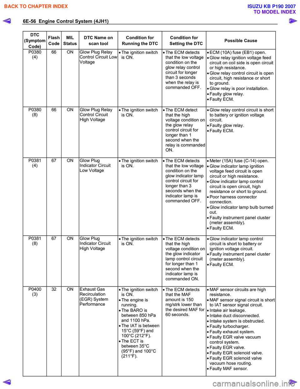
DTC
(Symptom Code) Flash
Code MIL
Status DTC Name on
scan tool Condition for
Running the DTC Condition for
Setting the DTC Possible Cause
P0380
(4) 66 ON Glow Plug Relay
Control Circuit Low
Voltage •
The ignition switch
is ON. •
The ECM detects
that the low voltage
condition on the
glow relay control
circuit for longer
than 3 seconds
when the relay is
commanded OFF.
•
ECM (10A) fuse (EB1) open.
• Glow relay ignition voltage feed
circuit on coil side is open circuit
or high resistance.
• Glow relay control circuit is open
circuit, high resistance or short
to ground.
• Glow relay is poor installation.
• Faulty glow relay.
• Faulty ECM.
P0380 (8) 66 ON
Glow Plug Relay
Control Circuit
High Voltage •
The ignition switch
is ON. •
The ECM detect
that the high
voltage condition on
the glow relay
control circuit for
longer than 1
second when the
relay is commanded
ON.
•
Glow relay control circuit is short
to battery or ignition voltage
circuit.
• Faulty glow relay.
• Faulty ECM.
P0381 (4) 67 ON Glow Plug
Indicator Circuit
Low Voltage •
The ignition switch
is ON.
•
The ECM detects
that the low voltage
condition on the
glow indicator lamp
control circuit for
longer than 3
seconds when the
indicator lamp is
commanded OFF.
•
Meter (15A) fuse (C-14) open.
• Glow indicator lamp ignition
voltage feed circuit is open
circuit or high resistance.
• Glow indicator lamp control
circuit is open circuit, high
resistance or short to ground.
• Poor harness connector
connection.
• Glow indicator lamp bulb burned
out.
• Faulty instrument panel cluster
(meter assembly).
• Faulty ECM.
P0381 (8) 67 ON Glow Plug
Indicator Circuit
High Voltage •
The ignition switch
is ON. •
The ECM detects
that the high
voltage condition on
the glow indicator
lamp control circuit
for longer than 1
second when the
indicator lamp is
commanded ON.
•
Glow indicator lamp control
circuit is short to battery or
ignition voltage circuit.
• Faulty instrument panel cluster
(meter assembly).
• Faulty ECM.
P0400 (3) 32 ON Exhaust Gas
Recirculation
(EGR) System
Performance •
The ignition switch
is ON.
• The engine is
running.
• The BARO is
between 850 hPa
and 1100 hPa.
• The IAT is between
15°C (59°F) and
100°C (212°F).
• The ECT is
between 35°C
(95°F) and 100°C
(211°F).
•
The ECM detects
that the MAF
amount is 150
mg/strk lower than
the desired MAF for
60 seconds.
•
MAF sensor circuits are high
resistance.
• MAF sensor signal circuit is short
to IAT sensor signal circuit.
• Intake air leakage.
• Intake duct disconnected.
• Intake system is obstructed.
• Faulty turbocharger.
• Faulty exhaust system.
• Faulty EGR valve vacuum
control system.
• Faulty EGR valve.
• Faulty EGR solenoid valve.
• Faulty EGR solenoid valve
vacuum hose routing.
• Faulty MAF sensor.
BACK TO CHAPTER INDEX
TO MODEL INDEX
ISUZU KB P190 2007
Page 1091 of 6020

Engine Control System (4JH1) 6E-57
DTC
(Symptom Code) Flash
Code MIL
Status DTC Name on
scan tool Condition for
Running the DTC Condition for
Setting the DTC Possible Cause
P0400
(4) 32 ON Exhaust Gas
Recirculation
(EGR) Solenoid
Circuit Low
Voltage •
The ignition switch
is ON.
•
The ECM detects
that the low voltage
condition on the
EGR solenoid valve
control circuit for
longer than 3
seconds when the
solenoid valve is
commanded OFF.
•
ECM (10A) fuse (EB1) open.
• EGR solenoid valve ignition
voltage feed circuit is open
circuit or high resistance.
• EGR solenoid valve control
circuit is open circuit, high
resistance or short to ground.
• Poor harness connector
connection.
• Faulty EGR solenoid valve.
• Faulty ECM.
P0400 (5) 32 ON Exhaust Gas
Recirculation
(EGR) System
Performance •
The ignition switch
is ON.
• The engine is
running.
• The BARO is
between 850 hPa
and 1100 hPa.
• The IAT is between
15°C (59°F) and
100°C (212°F).
• The ECT is
between 35°C
(95°F) and 100°C
(211°F).
•
The ECM detects
that the MAF
amount is 150
mg/strk higher than
the desired MAF for
60 seconds.
•
MAF sensor low reference circuit
is high resistance.
• Faulty EGR valve vacuum
control system.
• Faulty EGR valve.
• Faulty vacuum pump
• Faulty EGR solenoid valve.
• Faulty EGR solenoid valve
vacuum hose routing.
• Faulty MAF sensor.
• Faulty ECM.
P0400 (8) 32 ON Exhaust Gas
Recirculation
(EGR) Solenoid
Circuit High
Voltage
•
The ignition switch
is ON.
•
The ECM detects
that the high
voltage condition on
the EGR solenoid
valve control circuit
for longer than 3
seconds when the
solenoid valve is
commanded ON.
•
EGR solenoid valve control
circuit is short to battery or
ignition voltage circuit.
• Faulty EGR solenoid valve.
• Faulty ECM.
P0500 (1) 24 ON Vehicle Speed
Sensor (VSS)
Circuit
•
The ignition switch
is ON. •
The ECM detects
that the vehicle
speed is higher
than 200 km/h (125
MPH) for 5
seconds.
•
Vehicle speed too high.
• Electrical interference.
• Magnetic interference.
• Faulty A/T VSS. (2W D with A/T)
• Faulty VSS. (Except 2W D with
A/T)
• Faulty ECM.
P0500 (A) 24 ON Vehicle Speed
Sensor (VSS)
Circuit
•
The ignition switch
is ON. •
The ECM detects
that the vehicle
speed sensor signal
frequency is too
high for 0.6
seconds. •
Electrical interference.
• Magnetic interference.
• Faulty A/T VSS. (2W D with A/T)
• Faulty VSS. (Except 2W D with
A/T)
• Faulty ECM.
BACK TO CHAPTER INDEX
TO MODEL INDEX
ISUZU KB P190 2007
Page 1109 of 6020

Engine Control System (4JH1) 6E-75
DTC P0105 (Symptom Code 1) (Flash Code 34)
Circuit Description
The vacuum pressure sensor is installed to the
turbocharger wastegate control hose and it detects the
regulated vacuum pressure to the turbocharge
r
wastegate valve. The vacuum pressure sensor is a
transducer that varies voltage according to changes in
the vacuum pressure inside the vacuum hose. The
vacuum pressure sensor has the following circuits.
• 5 volts reference circuit
• Low reference circuit
• Vacuum pressure sensor signal circuit
The engine control module (ECM) supplies 5 volts to
the vacuum pressure sensor on the 5 volts reference
circuit. The ECM also provides a ground on the lo
w
reference circuit. The vacuum pressure sensor provides
a signal to the ECM on the vacuum pressure signal
circuit which is relative to the vacuum pressure changes
in the turbocharger wastegate valve control hose. The
ECM should detect a low signal voltage at a high
vacuum pressure and high signal voltage at a lo
w
vacuum pressure. The ECM monitors the vacuum
pressure sensor signal for voltage outside the normal
range of the vacuum pressure sensor. If the ECM
detects an excessively high vacuum pressure senso
r
signal voltage, this DTC will set.
Condition for Running the DTC
• The ignition switch is ON.
Condition for Setting the DTC
• The ECM detects that the vacuum pressure
sensor signal voltage is more than 4.4 volts for 3
seconds.
Action Taken When the DTC Sets
• The ECM illuminates the malfunction indicato
r
lamp (MIL) when the diagnostic runs and fails.
• The ECM limits fuel injection quantity.
• The ECM uses a barometric pressure of 615 hPa
for turbocharger wastegate valve control.
Condition for Clearing the MIL/DTC
• The ECM turns OFF the MIL when the diagnostic
runs and does not fail.
• A history DTC clears after 40 consecutive driving
cycles without a fault. Or clear with the scan tool.
Diagnostic Aids
• If an intermittent condition is suspected, refer to
Intermittent Conditions in this section.
Test Description
The number below refers to the step number on the
diagnostic table.
3. If the vacuum pressure sensor signal circuit between
the ECM and the sensor is normal, the sensor signal
voltage low DTC P0105 (Symptom Code 2) will set.
DTC P0105 (Symptom Code 1) (Flash Code 34)
Schematic Reference: Engine Controls Schematics
Connector End View Reference: Engine Controls
Connector End Views or Engine Control Module (ECM)
Connector End Views
Step Action Value(s) Yes No
1 Did you perform the Diagnostic System Check-
Engine Controls?
Go to Step 2 Go to Diagnostic
System Check-
Engine Controls
2 1. Install the scan tool. 2. Turn OFF the ignition for 30 seconds.
3. Start the engine.
4. Monitor the Diagnostic Trouble Code (DTC) Information with the scan tool.
Does the DTC fail this ignition?
Go to Step 3 Go to Diagnostic
Aids
3 1. Turn OFF the ignition. 2. Disconnect the vacuum pressure sensor harness connector.
3. Turn ON the ignition, with the engine OFF.
4. Monitor the DTC Information with the scan tool.
Does DTC P0105 (Symptom Code 2) set, but not
DTC P0105 (Symptom Code 1)?
Go to Step 4 Go to Step 6
4 1. Turn OFF the ignition. 2. Connect a test lamp between the low reference circuit of the vacuum pressure sensor harness
(pin 2 of C-124 connector) and battery voltage.
Does the test lamp illuminate?
Go to Step 5 Go to Step 7
BACK TO CHAPTER INDEX
TO MODEL INDEX
ISUZU KB P190 2007
Page 1110 of 6020
6E-76 Engine Control System (4JH1)
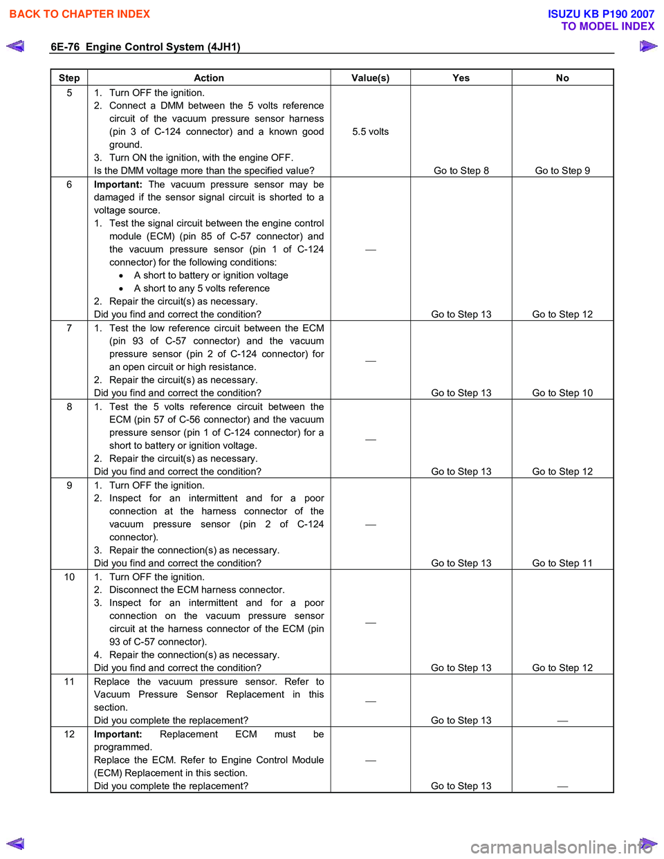
Step Action Value(s) Yes No
5 1. Turn OFF the ignition.
2. Connect a DMM between the 5 volts reference circuit of the vacuum pressure sensor harness
(pin 3 of C-124 connector) and a known good
ground.
3. Turn ON the ignition, with the engine OFF.
Is the DMM voltage more than the specified value? 5.5 volts
Go to Step 8 Go to Step 9
6 Important: The vacuum pressure sensor may be
damaged if the sensor signal circuit is shorted to a
voltage source.
1. Test the signal circuit between the engine control module (ECM) (pin 85 of C-57 connector) and
the vacuum pressure sensor (pin 1 of C-124
connector) for the following conditions: • A short to battery or ignition voltage
• A short to any 5 volts reference
2. Repair the circuit(s) as necessary.
Did you find and correct the condition?
Go to Step 13 Go to Step 12
7 1. Test the low reference circuit between the ECM (pin 93 of C-57 connector) and the vacuum
pressure sensor (pin 2 of C-124 connector) for
an open circuit or high resistance.
2. Repair the circuit(s) as necessary.
Did you find and correct the condition?
Go to Step 13 Go to Step 10
8 1. Test the 5 volts reference circuit between the ECM (pin 57 of C-56 connector) and the vacuum
pressure sensor (pin 1 of C-124 connector) for a
short to battery or ignition voltage.
2. Repair the circuit(s) as necessary.
Did you find and correct the condition?
Go to Step 13 Go to Step 12
9 1. Turn OFF the ignition. 2. Inspect for an intermittent and for a poor connection at the harness connector of the
vacuum pressure sensor (pin 2 of C-124
connector).
3. Repair the connection(s) as necessary.
Did you find and correct the condition?
Go to Step 13 Go to Step 11
10 1. Turn OFF the ignition. 2. Disconnect the ECM harness connector.
3. Inspect for an intermittent and for a poor connection on the vacuum pressure sensor
circuit at the harness connector of the ECM (pin
93 of C-57 connector).
4. Repair the connection(s) as necessary.
Did you find and correct the condition?
Go to Step 13 Go to Step 12
11 Replace the vacuum pressure sensor. Refer to Vacuum Pressure Sensor Replacement in this
section.
Did you complete the replacement?
Go to Step 13
12 Important: Replacement ECM must be
programmed.
Replace the ECM. Refer to Engine Control Module
(ECM) Replacement in this section.
Did you complete the replacement?
Go to Step 13
BACK TO CHAPTER INDEX
TO MODEL INDEX
ISUZU KB P190 2007
Page 1112 of 6020

6E-78 Engine Control System (4JH1)
DTC P0105 (Symptom Code 2) (Flash Code 34)
Circuit Description
The vacuum pressure sensor is installed to the
turbocharger wastegate control hose and it detects the
regulated vacuum pressure to the turbocharge
r
wastegate valve. The vacuum pressure sensor is a
transducer that varies voltage according to changes in
the vacuum pressure inside the vacuum hose. The
vacuum pressure sensor has the following circuits.
• 5 volts reference circuit
• Low reference circuit
• Vacuum pressure sensor signal circuit
The engine control module (ECM) supplies 5 volts to
the vacuum pressure sensor on the 5 volts reference
circuit. The ECM also provides a ground on the lo
w
reference circuit. The vacuum pressure sensor provides
a signal to the ECM on the vacuum pressure signal
circuit which is relative to the vacuum pressure changes
in the turbocharger wastegate valve control hose. The
ECM should detect a low signal voltage at a high
vacuum pressure and high signal voltage at a lo
w
vacuum pressure. The ECM monitors the vacuum
pressure sensor signal for voltage outside the normal
range of the vacuum pressure sensor. If the ECM
detects an excessively low vacuum pressure senso
r
signal voltage, this DTC will set.
Condition for Running the DTC
• The ignition switch is ON.
Condition for Setting the DTC
• The ECM detects that the vacuum pressure
sensor signal voltage is less than 0.5 volts for 3
seconds.
Action Taken When the DTC Sets
• The ECM illuminates the malfunction indicato
r
lamp (MIL) when the diagnostic runs and fails.
• The ECM limits fuel injection quantity.
• The ECM uses a barometric pressure of 615 hPa
for turbocharger wastegate valve control.
Condition for Clearing the MIL/DTC
• The ECM turns OFF the MIL when the diagnostic
runs and does not fail.
• A history DTC clears after 40 consecutive driving
cycles without a fault. Or clear with the scan tool.
Diagnostic Aids
• If an intermittent condition is suspected, refer to
Intermittent Conditions in this section.
Test Description
The number below refers to the step number on the
diagnostic table.
4. If the vacuum pressure sensor signal circuit between
the ECM and the sensor is normal, the sensor signal
voltage high DTC P0105 (Symptom Code 1) will set.
DTC P0105 (Symptom Code 2) (Flash Code 34)
Schematic Reference: Engine Controls Schematics
Connector End View Reference: Engine Controls
Connector End Views or Engine Control Module (ECM)
Connector End Views
Step Action Value(s) Yes No
1 Did you perform the Diagnostic System Check-
Engine Controls?
Go to Step 2 Go to Diagnostic
System Check-
Engine Controls
2 1. Install the scan tool. 2. Turn OFF the ignition for 30 seconds.
3. Start the engine.
4. Monitor the Diagnostic Trouble Code (DTC) Information with the scan tool.
Does the DTC fail this ignition?
Go to Step 3 Go to Diagnostic
Aids
3 1. Turn OFF the ignition. 2. Disconnect the vacuum pressure sensor harness connector.
3. Connect a DMM between the 5 volts reference circuit of the vacuum pressure sensor harness
(pin 3 of C-124 connector) and a known good
ground.
4. Turn ON the ignition, with the engine OFF.
Is the DMM voltage more than the specified value? 4.5 volts
Go to Step 4 Go to Step 5
BACK TO CHAPTER INDEX
TO MODEL INDEX
ISUZU KB P190 2007