heating ISUZU KB P190 2007 Workshop Repair Manual
[x] Cancel search | Manufacturer: ISUZU, Model Year: 2007, Model line: KB P190, Model: ISUZU KB P190 2007Pages: 6020, PDF Size: 70.23 MB
Page 1 of 6020
1
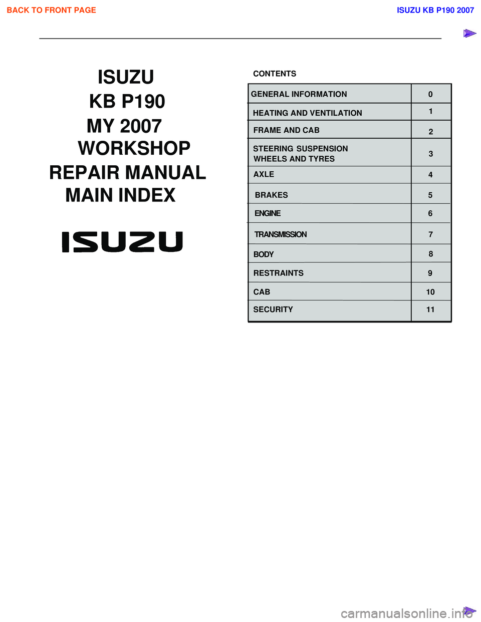
WORKSHOP
REPAIR MANUAL
GE NERAL INFORMATION 0
HEATING AND VENTILATION
BRAKESMAIN INDEX ISUZU
CONTENTS
WHEELS AND TYRES
4
5
BODY 8
SECURITY 11 SUSPENSION
3
STEERING
2
AXLE
FRAME AND CAB
ENGINE
6
TRANSMISSION 7
MY 2007
RESTRAINTS 9
CAB 10
BACK TO FRONT PAGE
KB P190
ISUZU KB P190 2007
Page 55 of 6020
HEATER AND AIR CONDITIONING 1-21
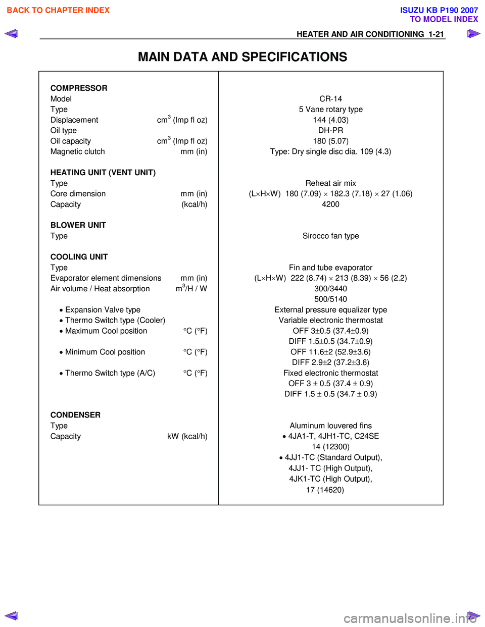
MAIN DATA AND SPECIFICATIONS
COMPRESSOR
Model CR-14
Type 5 Vane rotary type
Displacement cm3 (lmp fl oz) 144 (4.03)
Oil type DH-PR
Oil capacity cm3 (lmp fl oz) 180 (5.07)
Magnetic clutch mm (in) Type: Dry single disc dia. 109 (4.3)
HEATING UNIT (VENT UNIT)
Type Reheat air mix
Core dimension mm (in) (L×H ×W ) 180 (7.09) × 182.3 (7.18) × 27 (1.06)
Capacity (kcal/h) 4200
BLOWER UNIT
Type Sirocco fan type
COOLING UNIT
Type Fin and tube evaporator
Evaporator element dimensions mm (in) (L×H ×W ) 222 (8.74) × 213 (8.39) × 56 (2.2)
Air volume / Heat absorption m3/H / W
300/3440
500/5140
• Expansion Valve type External pressure equalizer type
• Thermo Switch type (Cooler) Variable electronic thermostat
• Maximum Cool position °C ( °F) OFF 3± 0.5 (37.4 ±0.9)
DIFF 1.5 ±0.5 (34.7 ±0.9)
• Minimum Cool position °C ( °F)
OFF 11.6
±2 (52.9 ±3.6)
DIFF 2.9 ±2 (37.2 ±3.6)
• Thermo Switch type (A/C) °C ( °F) Fixed electronic thermostat
OFF 3 ± 0.5 (37.4 ± 0.9)
DIFF 1.5 ± 0.5 (34.7 ± 0.9)
CONDENSER
Type Aluminum louvered fins
Capacity kW (kcal/h) •
4JA1-T, 4JH1-TC, C24SE
14 (12300)
• 4JJ1-TC (Standard Output),
4JJ1- TC (High Output), 4JK1-TC (High Output),
17 (14620)
BACK TO CHAPTER INDEX
TO MODEL INDEX
ISUZU KB P190 2007
Page 786 of 6020
TROUBLESHOOTING 6 – 1
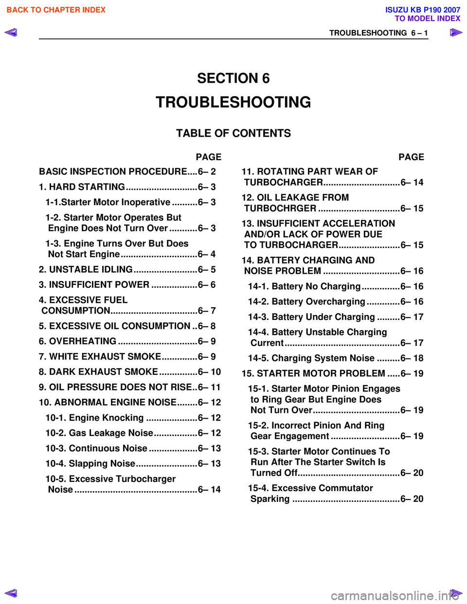
BASIC INSPECTION PROCEDURE....6– 2
1. HARD STARTING ............................6– 3
1-1.Starter Motor Inoperative ..........6– 3
1-2. Starter Motor Operates But
Engine Does Not Turn Over ...........6– 3
1-3. Engine Turns Over But Does
Not Start Engine ..............................6– 4
2. UNSTABLE IDLING .........................6– 5
3. INSUFFICIENT POWER ..................6– 6
4. EXCESSIVE FUEL
CONSUMPTION..................................6– 7
5. EXCESSIVE OIL CONSUMPTION ..6– 8
6. OVERHEATING ...............................6– 9
7. WHITE EXHAUST SMOKE..............6– 9
8. DARK EXHAUST SMOKE ...............6– 10
9. OIL PRESSURE DOES NOT RISE..6– 11
10. ABNORMAL ENGINE NOISE ........6– 12
10-1. Engine Knocking ....................6– 12
10-2. Gas Leakage Noise .................6– 12
10-3. Continuous Noise ...................6– 13
10-4. Slapping Noise ........................6– 13
10-5. Excessive Turbocharger
Noise ................................................6– 14
11. ROTATING PART WEAR OF
TURBOCHARGER.............................. 6– 14
12. OIL LEAKAGE FROM
TURBOCHRGER ................................ 6– 15
13. INSUFFICIENT ACCELERATION
AND/OR LACK OF POWER DUE
TO TURBOCHARGER........................ 6– 15
14. BATTERY CHARGING AND
NOISE PROBLEM .............................. 6– 16
14-1. Battery No Charging ............... 6– 16
14-2. Battery Overcharging ............. 6– 16
14-3. Battery Under Charging ......... 6– 17
14-4. Battery Unstable Charging
Current ............................................. 6– 17
14-5. Charging System Noise ......... 6– 18
15. STARTER MOTOR PROBLEM ..... 6– 19
15-1. Starter Motor Pinion Engages
to Ring Gear But Engine Does
Not Turn Over .................................. 6– 19
15-2. Incorrect Pinion And Ring
Gear Engagement ........................... 6– 19
15-3. Starter Motor Continues To
Run After The Starter Switch Is
Turned Off........................................ 6– 20
15-4. Excessive Commutator
Sparking .......................................... 6– 20
SECTION 6
TROUBLESHOOTING
TABLE OF CONTENTS
PAGE PAGE
BACK TO CHAPTER INDEX
TO MODEL INDEX
ISUZU KB P190 2007
Page 794 of 6020

TROUBLESHOOTING 6 – 9
6. Overheating
Step Action Value(s) Yes No
1 Was the engine coolant level OK? —
Go to Step 2 Replenish the
coolant
2 Was the water leakage or the radiator restriction found? (Include radiator cap) —
Repair or
replace the
leakage part. Go to Step 3
3 Was the fan belt slippage found? — Tension or
replace the fan belt. Go to Step 4
4 Was the fan clutch working completely? —
Go to Step 5 Replace the fan
clutch
assembly.
5 Was the oil leakage found from fan clutch? — Replace the fan
clutch
assembly Go to Step 6
6 Was the thermostat working normally? —
Go to Step 7 Replace the
thermostat.
7 Was the water pump working OK? —
Go to Step 8 Replace the
water pump assembly.
8 Was the restriction by the foreign materials in the cooling system found? For example, clog the water
hose between the cylinder body and radiator etc.. —
Clean or
replace the clog part. Go to Step 9
9 Was the water leakage found from the sealing cap
on the cylinder body? —
Replace the
sealing cap or replace the
cylinder body. Go to Step 10
10 Are any DTC stored? — Go to indicated
DTC. Solved
7. White Exhaust Smoke
Step Action Value(s) Yes No
1 Was the compression pressure OK? 3.0 MPa
(31.0 kg/cm2,
441 psi) at 200 rpm
Go to Step 2 Readjust the
valve clearance or replace the cylinder head gasket or
cylinder liner or
piston or piston ring or valve and relation parts.
2 Was the PCV (Positive Crankcase Ventilation) valve working completely? —
Go to Step 3 Repair or
replace the
PCV valve.
3 Was the turbocharger working completely? —
Go to Step 4 Replace the
turbocharger.
4 Are any DTC stored? — Go to indicated
DTC Solved
BACK TO CHAPTER INDEX
TO MODEL INDEX
ISUZU KB P190 2007
Page 951 of 6020
ENGINE COOLING 6B – 7
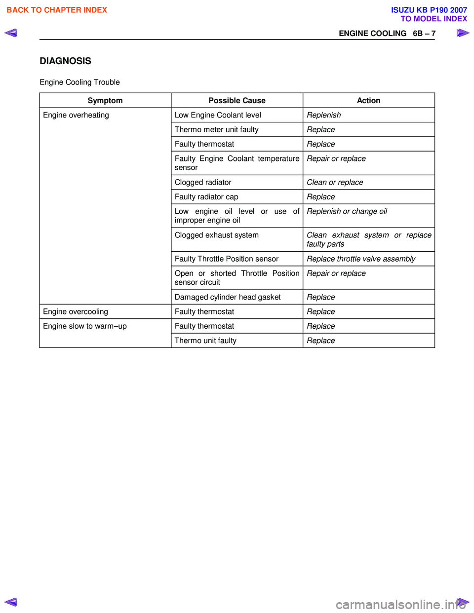
DIAGNOSIS
Engine Cooling Trouble
Symptom Possible Cause Action
Low Engine Coolant level Replenish
Thermo meter unit faulty Replace
Faulty thermostat Replace
Faulty Engine Coolant temperature
sensor Repair or replace
Clogged radiator
Clean or replace
Faulty radiator cap Replace
Low engine oil level or use of
improper engine oil Replenish or change oil
Clogged exhaust system
Clean exhaust system or replace
faulty parts
Faulty Throttle Position sensor Replace throttle valve assembly
Open or shorted Throttle Position
sensor circuit Repair or replace
Engine overheating
Damaged cylinder head gasket Replace
Engine overcooling Faulty thermostat Replace
Faulty thermostat Replace Engine slow to warm–up
Thermo unit faulty Replace
BACK TO CHAPTER INDEX
TO MODEL INDEX
ISUZU KB P190 2007
Page 961 of 6020
ENGINE COOLING 6B – 17
Inspection and Repair
Make the necessary adjustments, repairs, and part
replacements if excessive wear or damage is discovered
during inspection.
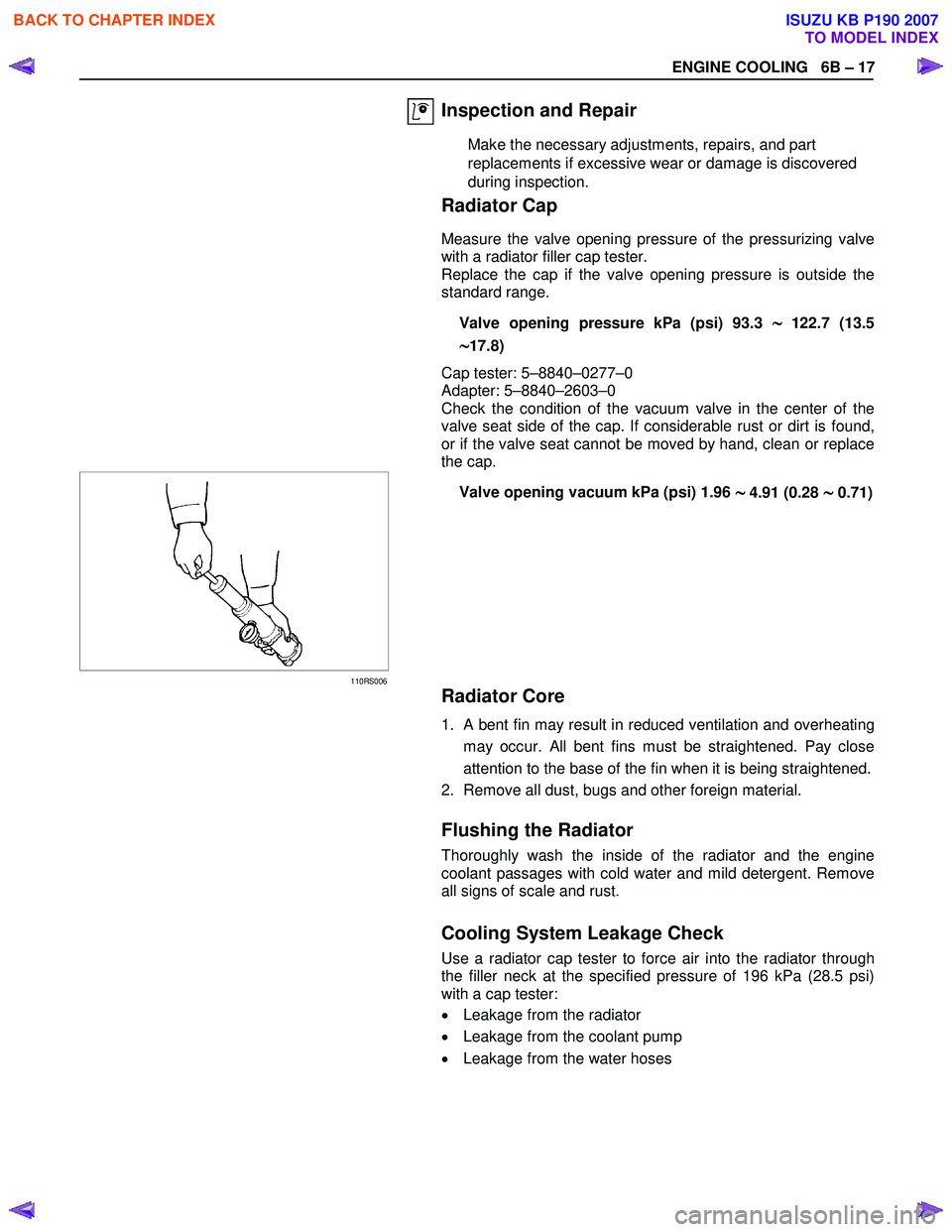
Radiator Cap
Measure the valve opening pressure of the pressurizing valve
with a radiator filler cap tester.
Replace the cap if the valve opening pressure is outside the
standard range.
Valve opening pressure kPa (psi) 93.3
∼
∼∼
∼122.7 (13.5
∼
∼∼
∼17.8)
Cap tester: 5–8840–0277–0
Adapter: 5–8840–2603–0
Check the condition of the vacuum valve in the center of the
valve seat side of the cap. If considerable rust or dirt is found,
or if the valve seat cannot be moved by hand, clean or replace
the cap.
110RS006
Valve opening vacuum kPa (psi) 1.96 ∼
∼∼
∼ 4.91 (0.28 ∼
∼∼
∼ 0.71)
Radiator Core
1. A bent fin may result in reduced ventilation and overheating
may occur. All bent fins must be straightened. Pay close
attention to the base of the fin when it is being straightened.
2. Remove all dust, bugs and other foreign material.
Flushing the Radiator
Thoroughly wash the inside of the radiator and the engine
coolant passages with cold water and mild detergent. Remove
all signs of scale and rust.
Cooling System Leakage Check
Use a radiator cap tester to force air into the radiator through
the filler neck at the specified pressure of 196 kPa (28.5 psi)
with a cap tester:
• Leakage from the radiator
• Leakage from the coolant pump
• Leakage from the water hoses
BACK TO CHAPTER INDEX
TO MODEL INDEX
ISUZU KB P190 2007
Page 1002 of 6020
SECTION 6D
ENGINE ELECTRICAL
TABLE OF CONTENTS
PAGE
Main Data and Specifications ......................................................................................... 6D - 2
General Description ........................................................................................................ 6D - 3
Torque Specifications ..................................................................................................... 6D - 5
Generator ...................................................................................................................... ... 6D - 7
Removal and Installation ............................................................................................ 6D - 7
Disassembly ................................................................................................................ 6D - 9
Inspection and Repair ................................................................................................. 6D - 12
Reassembly ................................................................................................................. 6D - 18
Starter Motor .................................................................................................................. .. 6D - 22
Removal and Installation ............................................................................................ 6D - 22
Disassembly ................................................................................................................ 6D - 23
Inspection and Repair ................................................................................................. 6D - 26
Reassembly ................................................................................................................. 6D - 29
Pre-heating System ......................................................................................................... 6D -33
Inspection and Repair ................................................................................................. 6D -33
Glow Relay ................................................................................................................... 6D -33
Glow Plug..................................................................................................................... 6D -33
EGR System ................................................................................................................. 6D -33
ENGINE ELECTRICAL 6D – 1
BACK TO CHAPTER INDEX
TO MODEL INDEX
ISUZU KB P190 2007
Page 1034 of 6020
ENGINE ELECTRICAL 6D – 33
PRE-HEATING SYSTEM
INSPECTION AND REPAIR
Make the necessary adjustments, repairs, and part replacement if excessive wear of damage is discovered during
inspection.
VISUAL CHECK
Check the main fuses and glow indicator for damage.
Replace the part(s) if required.
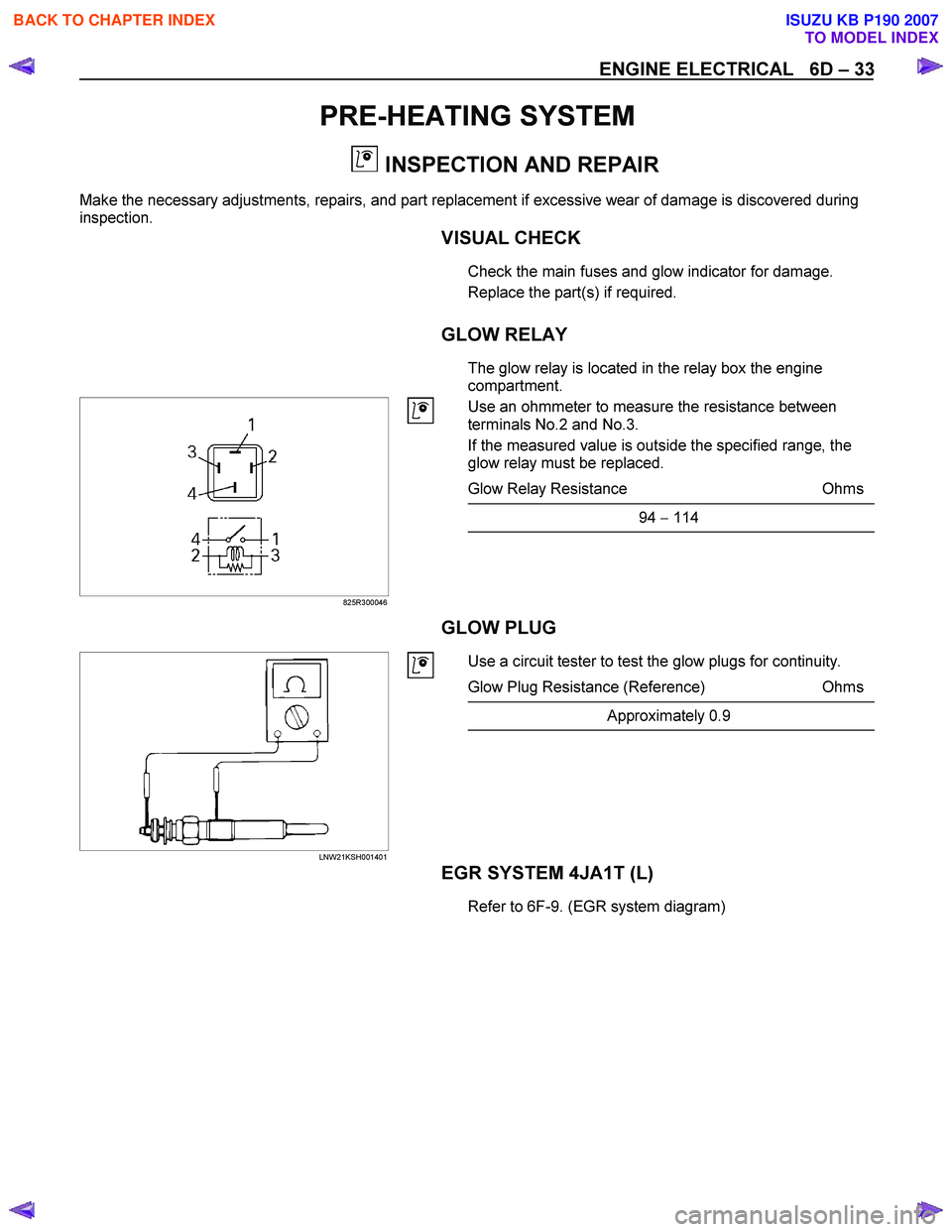
GLOW RELAY
The glow relay is located in the relay box the engine
compartment.
825R300046
Use an ohmmeter to measure the resistance between
terminals No.2 and No.3.
If the measured value is outside the specified range, the
glow relay must be replaced.
Glow Relay Resistance Ohms
94 − 114
GLOW PLUG
LNW21KSH001401
Use a circuit tester to test the glow plugs for continuity.
Glow Plug Resistance (Reference) Ohms
Approximately 0.9
EGR SYSTEM 4JA1T (L)
Refer to 6F-9. (EGR system diagram)
BACK TO CHAPTER INDEX
TO MODEL INDEX
ISUZU KB P190 2007
Page 1073 of 6020
Engine Control System (4JH1) 6E-39
Brake Pedal 2 Switch
This parameter displays the state of the brake pedal 2
switch as determined by the ECM terminal (pin 65). The
scan tool will display Released or Applied. Released
indicates the brake pedal is not being pushed down.
Applied indicates the brake switch is being depressed.
Clutch Pedal Switch (M/T Only)
This parameter displays the state of the clutch pedal as
determined by the ECM terminal (pin 31) based on an
input from the clutch pedal switch. The scan tool will
display Release or Applied. Release indicates the clutch
pedal is not being push down. Applied indicates the
clutch switch is being depressed.
Vehicle Speed
This parameter displays the vehicle speed calculated b
y
the ECM based on an input from the vehicle speed
sensor (VSS). The scan tool will display a high value at
higher vehicle speeds, and low value at lower vehicle
speeds.
Glow Relay Command
This parameter displays the commanded state of the
glow plug relay control circuit (pin 94). The scan tool will
display On or Off. On indicates the glow plug rela
y
control circuit is being grounded by the ECM, allowing
voltage to the glow plugs. Off indicates the glow plug
relay is not being commanded On by the ECM.
Glow Indicator Lamp Command
This parameter displays the commanded state of the
glow indicator lamp control circuit (pin 43). The glo
w
indicator lamp should be On when the scan tool
indicates On. The glow indicator should be Off when the
scan tool indicates Off.
Malfunction Indicator Lamp (MIL) Command
This parameter displays the commanded state of the
malfunction indicator lamp (MIL) control circuit (pin 42).
The MIL should be On when the scan tool indicates On.
The MIL should be Off when the scan tool indicates Off.
The ECM will command the MIL On for a certain length
of time when the ignition is On with the engine Off in
order to perform a bulb check.
A/C Request Signal
This parameter displays the state of the air conditioning
(A/C) request input to the ECM terminal (pin 33) from
the heating, ventilation, and air conditioning (HVAC)
controls. The scan tool will display On or Off. On
indicates the ECM is receiving a request from the HVAC
system to ground the A/C compressor relay control
circuit, engaging the
A/C compressor clutch. Off
indicates the ECM is not receiving a request from the
HVAC system.
A/C Relay Command
This parameter displays the commanded state of the
A/C compressor relay control circuit (pin 41). The scan
tool will display On or Off. On indicates the
A/C
compressor relay control circuit is being grounded b
y
the ECM, allowing voltage to the A/C compressor
clutch. Off indicates the A/C compressor relay is not
being commanded On by the ECM.
BACK TO CHAPTER INDEX
TO MODEL INDEX
ISUZU KB P190 2007
Page 1210 of 6020
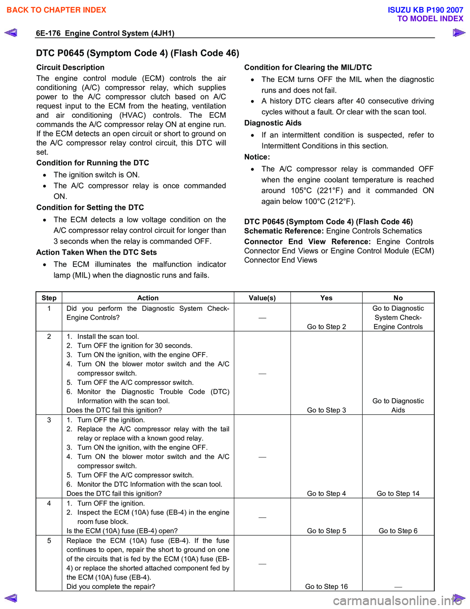
6E-176 Engine Control System (4JH1)
DTC P0645 (Symptom Code 4) (Flash Code 46)
Circuit Description
The engine control module (ECM) controls the ai
r
conditioning (A/C) compressor relay, which supplies
power to the A/C compressor clutch based on A/C
request input to the ECM from the heating, ventilation
and air conditioning (HVAC) controls. The ECM
commands the A/C compressor relay ON at engine run.
If the ECM detects an open circuit or short to ground on
the A/C compressor relay control circuit, this DTC will
set.
Condition for Running the DTC
• The ignition switch is ON.
• The A/C compressor relay is once commanded
ON.
Condition for Setting the DTC
• The ECM detects a low voltage condition on the
A/C compressor relay control circuit for longer than
3 seconds when the relay is commanded OFF.
Action Taken When the DTC Sets
• The ECM illuminates the malfunction indicato
r
lamp (MIL) when the diagnostic runs and fails.
Condition for Clearing the MIL/DTC
• The ECM turns OFF the MIL when the diagnostic
runs and does not fail.
• A history DTC clears after 40 consecutive driving
cycles without a fault. Or clear with the scan tool.
Diagnostic Aids
• If an intermittent condition is suspected, refer to
Intermittent Conditions in this section.
Notice:
• The A/C compressor relay is commanded OFF
when the engine coolant temperature is reached
around 105°C (221°F) and it commanded ON
again below 100°C (212°F).
DTC P0645 (Symptom Code 4) (Flash Code 46)
Schematic Reference: Engine Controls Schematics
Connector End View Reference: Engine Controls
Connector End Views or Engine Control Module (ECM)
Connector End Views
Step Action Value(s) Yes No
1 Did you perform the Diagnostic System Check-
Engine Controls?
Go to Step 2 Go to Diagnostic
System Check-
Engine Controls
2 1. Install the scan tool. 2. Turn OFF the ignition for 30 seconds.
3. Turn ON the ignition, with the engine OFF.
4. Turn ON the blower motor switch and the A/C compressor switch.
5. Turn OFF the A/C compressor switch.
6. Monitor the Diagnostic Trouble Code (DTC) Information with the scan tool.
Does the DTC fail this ignition?
Go to Step 3 Go to Diagnostic
Aids
3 1. Turn OFF the ignition. 2. Replace the A/C compressor relay with the tail relay or replace with a known good relay.
3. Turn ON the ignition, with the engine OFF.
4. Turn ON the blower motor switch and the A/C compressor switch.
5. Turn OFF the A/C compressor switch.
6. Monitor the DTC Information with the scan tool.
Does the DTC fail this ignition?
Go to Step 4 Go to Step 14
4 1. Turn OFF the ignition. 2. Inspect the ECM (10A) fuse (EB-4) in the engine room fuse block.
Is the ECM (10A) fuse (EB-4) open?
Go to Step 5 Go to Step 6
5 Replace the ECM (10A) fuse (EB-4). If the fuse continues to open, repair the short to ground on one
of the circuits that is fed by the ECM (10A) fuse (EB-
4) or replace the shorted attached component fed by
the ECM (10A) fuse (EB-4).
Did you complete the repair?
Go to Step 16
BACK TO CHAPTER INDEX
TO MODEL INDEX
ISUZU KB P190 2007