indicator ISUZU KB P190 2007 Workshop Repair Manual
[x] Cancel search | Manufacturer: ISUZU, Model Year: 2007, Model line: KB P190, Model: ISUZU KB P190 2007Pages: 6020, PDF Size: 70.23 MB
Page 1954 of 6020
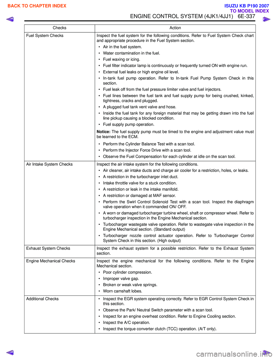
ENGINE CONTROL SYSTEM (4JK1/4JJ1) 6E-337
Fuel System ChecksInspect the fuel system for the following conditions. Refer to Fuel System Check chart
and appropriate procedure in the Fuel System section.
• Air in the fuel system.
• Water contamination in the fuel.
• Fuel waxing or icing.
• Fuel filter indicator lamp is continuously or frequently turned ON with engine run.
• External fuel leaks or high engine oil level.
• In-tank fuel pump operation. Refer to In-tank Fuel Pump System Check in this section.
• Fuel leak off from the fuel pressure limiter valve and fuel injectors.
• Fuel lines between the fuel tank and fuel supply pump for being crushed, kinked, tightness, cracks and plugged.
• A plugged fuel tank vent valve and hose.
• Inside the fuel tank for any foreign material that may be getting drawn into the fuel line pickup causing a blocked condition.
• Fuel supply pump operation.
Notice: The fuel supply pump must be timed to the engine and adjustment value must
be learned to the ECM.
• Perform the Cylinder Balance Test with a scan tool.
• Perform the Injector Force Drive with a scan tool.
• Observe the Fuel Compensation for each cylinder at idle on the scan tool.
Air Intake System Checks Inspect the air intake system for the following conditions.
• Air cleaner, air intake ducts and charge air cooler for a restriction, holes, or leaks.
• A restriction in the turbocharger inlet duct.
• Intake throttle valve for a stuck condition.
• A restriction or leak in the intake manifold.
• A restriction or damaged at MAF sensor.
• Perform the Swirl Control Solenoid Test with a scan tool. Inspect the diaphragm valve operation when it commanded ON/ OFF.
• A worn or damaged turbocharger turbine wheel, shaft or compressor wheel. Refer to turbocharger inspection in the Engine Mechanical section.
• Turbocharger wastegate valve operation. Refer to wastegate valve inspection in the Engine Mechanical section. (Standard output)
• Turbocharger nozzle control actuator operation. Refer to Turbocharger Control System Check in this section. (High output)
Exhaust System Checks Inspect the exhaust system for a possible restriction. Refer to the Exhaust System
section.
Engine Mechanical Checks Inspect the engine mechanical for the following conditions. Refer to the Engine
Mechanical section.
• Poor cylinder compression.
• Improper valve gap.
• Broken or weak valve springs.
• Worn camshaft lobes.
Additional Checks • Inspect the EGR system operating correctly. Refer to EGR Control System Check in
this section.
• Observe the Park/ Neutral Switch parameter with a scan tool.
• Inspect for an engine overheat condition. Refer to Engine Cooling section.
• Inspect the A/C operation.
• Inspect the torque converter clutch (TCC) operation. (A/T only).
Checks
Action
BACK TO CHAPTER INDEX
TO MODEL INDEX
ISUZU KB P190 2007
Page 1956 of 6020
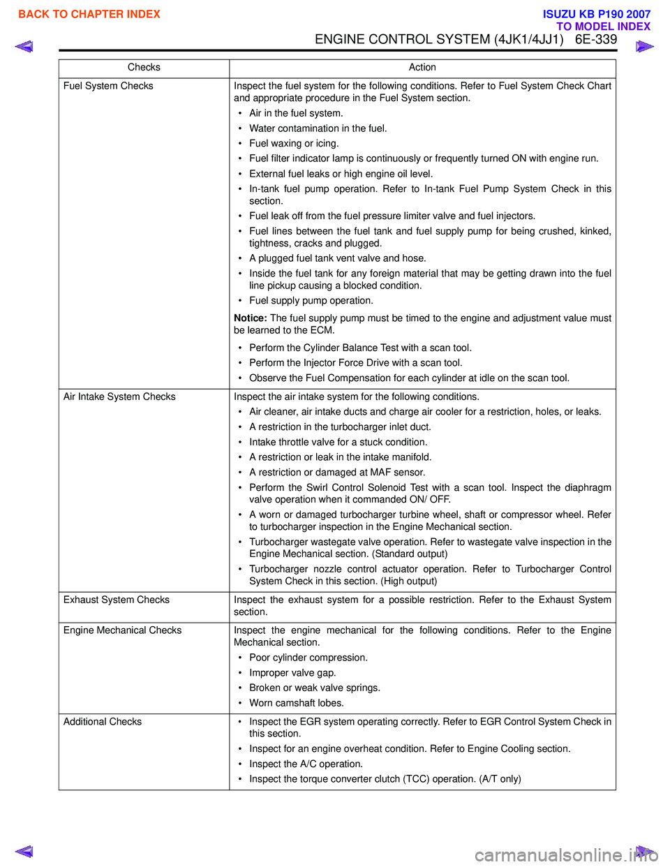
ENGINE CONTROL SYSTEM (4JK1/4JJ1) 6E-339
Fuel System ChecksInspect the fuel system for the following conditions. Refer to Fuel System Check Chart
and appropriate procedure in the Fuel System section.
• Air in the fuel system.
• Water contamination in the fuel.
• Fuel waxing or icing.
• Fuel filter indicator lamp is continuously or frequently turned ON with engine run.
• External fuel leaks or high engine oil level.
• In-tank fuel pump operation. Refer to In-tank Fuel Pump System Check in this section.
• Fuel leak off from the fuel pressure limiter valve and fuel injectors.
• Fuel lines between the fuel tank and fuel supply pump for being crushed, kinked, tightness, cracks and plugged.
• A plugged fuel tank vent valve and hose.
• Inside the fuel tank for any foreign material that may be getting drawn into the fuel line pickup causing a blocked condition.
• Fuel supply pump operation.
Notice: The fuel supply pump must be timed to the engine and adjustment value must
be learned to the ECM.
• Perform the Cylinder Balance Test with a scan tool.
• Perform the Injector Force Drive with a scan tool.
• Observe the Fuel Compensation for each cylinder at idle on the scan tool.
Air Intake System Checks Inspect the air intake system for the following conditions.
• Air cleaner, air intake ducts and charge air cooler for a restriction, holes, or leaks.
• A restriction in the turbocharger inlet duct.
• Intake throttle valve for a stuck condition.
• A restriction or leak in the intake manifold.
• A restriction or damaged at MAF sensor.
• Perform the Swirl Control Solenoid Test with a scan tool. Inspect the diaphragm valve operation when it commanded ON/ OFF.
• A worn or damaged turbocharger turbine wheel, shaft or compressor wheel. Refer to turbocharger inspection in the Engine Mechanical section.
• Turbocharger wastegate valve operation. Refer to wastegate valve inspection in the Engine Mechanical section. (Standard output)
• Turbocharger nozzle control actuator operation. Refer to Turbocharger Control System Check in this section. (High output)
Exhaust System Checks Inspect the exhaust system for a possible restriction. Refer to the Exhaust System
section.
Engine Mechanical Checks Inspect the engine mechanical for the following conditions. Refer to the Engine
Mechanical section.
• Poor cylinder compression.
• Improper valve gap.
• Broken or weak valve springs.
• Worn camshaft lobes.
Additional Checks • Inspect the EGR system operating correctly. Refer to EGR Control System Check in
this section.
• Inspect for an engine overheat condition. Refer to Engine Cooling section.
• Inspect the A/C operation.
• Inspect the torque converter clutch (TCC) operation. (A/T only)
Checks
Action
BACK TO CHAPTER INDEX
TO MODEL INDEX
ISUZU KB P190 2007
Page 1970 of 6020

ENGINE CONTROL SYSTEM (4JK1/4JJ1) 6E-353
Description and Operation
Engine Control Module (ECM) Description
Engine Control Module (ECM) Service Precautions
Important:The symbol ! warns you of an electric shock
hazard. To avoid shock and possible serious injury, DO NOT
touch the terminals. When disconnecting the harness
connectors, always turn OFF the ignition switch or disconnect
the battery cable.
The engine control module (ECM) is designed to
withstand normal current draws associated with vehicle
operation. Avoid overloading any circuit. When testing
for opens and shorts, do not ground or apply voltage to
any of the ECM circuits unless instructed to do so. In
some cases, these circuits should only be tested using
a DMM. The ECM should remain connected to the
ECM harness.
The ECM is located inside of engine compartment via
mounting bracket and is behind air cleaner case. The
ECM mainly controls the following. • The fuel system control
• The exhaust gas recirculation (EGR) system control
• The preheating (glow) system control
• The A/C compressor control
• The immobilizer control
• On-board diagnostics for engine control
The ECM constantly observes the information from
various sensors. The ECM controls the systems that
affect vehicle performance. The ECM performs the
diagnostic function of the system. The ECM can
recognize operational problems, alert the driver
through the malfunction indicator lamp (MIL), and store
diagnostic trouble codes (DTCs). DTCs identify the
system faults to aid the technician in making repairs.
RTW56ESH000201
RTW56ESH004401
BACK TO CHAPTER INDEX
TO MODEL INDEX
ISUZU KB P190 2007
Page 1971 of 6020
6E-354 ENGINE CONTROL SYSTEM (4JK1/4JJ1)
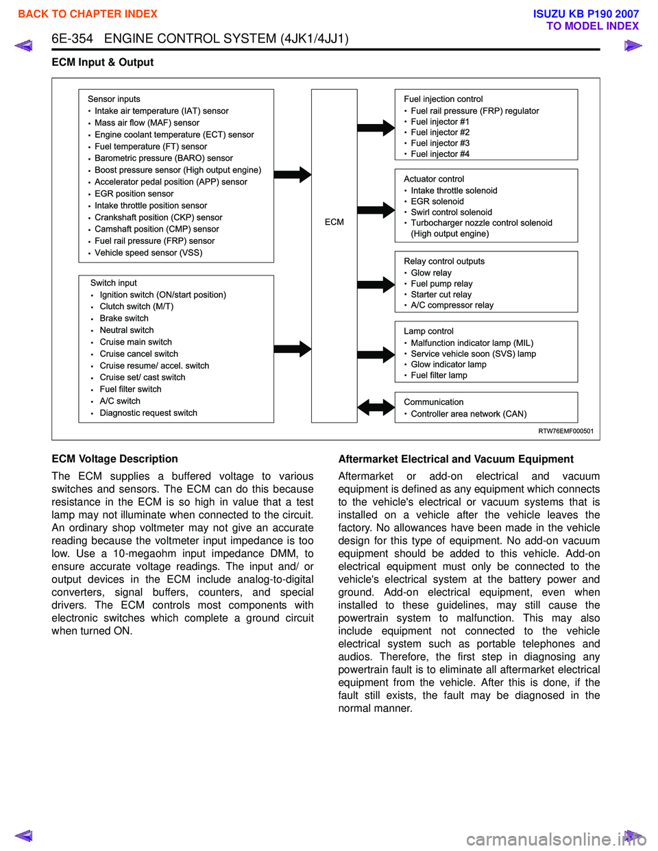
ECM Input & Output
ECM Voltage Description
The ECM supplies a buffered voltage to various
switches and sensors. The ECM can do this because
resistance in the ECM is so high in value that a test
lamp may not illuminate when connected to the circuit.
An ordinary shop voltmeter may not give an accurate
reading because the voltmeter input impedance is too
low. Use a 10-megaohm input impedance DMM, to
ensure accurate voltage readings. The input and/ or
output devices in the ECM include analog-to-digital
converters, signal buffers, counters, and special
drivers. The ECM controls most components with
electronic switches which complete a ground circuit
when turned ON. Aftermarket Electrical and Vacuum Equipment
Aftermarket or add-on electrical and vacuum
equipment is defined as any equipment which connects
to the vehicle's electrical or vacuum systems that is
installed on a vehicle after the vehicle leaves the
factory. No allowances have been made in the vehicle
design for this type of equipment. No add-on vacuum
equipment should be added to this vehicle. Add-on
electrical equipment must only be connected to the
vehicle's electrical system at the battery power and
ground. Add-on electrical equipment, even when
installed to these guidelines, may still cause the
powertrain system to malfunction. This may also
include equipment not connected to the vehicle
electrical system such as portable telephones and
audios. Therefore, the first step in diagnosing any
powertrain fault is to eliminate all aftermarket electrical
equipment from the vehicle. After this is done, if the
fault still exists, the fault may be diagnosed in the
normal manner.
RTW76EMF000501
Sensor inputs
· Intake air temperature (IAT) sensor
· Mass air flow (MAF) sensor
· Engine coolant temperature (ECT) sensor
· Fuel temperature (FT) sensor
· Barometric pressure (BARO) sensor
· Boost pressure sensor (High output engine)
· Accelerator pedal position (APP) sensor
· EGR position sensor
· Intake throttle position sensor
· Crankshaft position (CKP) sensor
· Camshaft position (CMP) sensor
· Fuel rail pressure (FRP) sensor
· Vehicle speed sensor (VSS)
Switch input
· Ignition switch (ON/start position)
· Clutch switch (M/T)
· Brake switch
· Neutral switch
· Cruise main switch
· Cruise cancel switch
· Cruise resume/ accel. switch
· Cruise set/ cast switch
· Fuel filter switch
· A/C switch
· Diagnostic request switch
Fuel injection control
· Fuel rail pressure (FRP) regulator
· Fuel injector #1
· Fuel injector #2
· Fuel injector #3
· Fuel injector #4
Relay control outputs
· Glow relay
· Fuel pump relay
· Starter cut relay
· A/C compressor relay
Lamp control
· Malfunction indicator lamp (MIL)
· Service vehicle soon (SVS) lamp
· Glow indicator lamp
· Fuel filter lamp
Communication
· Controller area network (CAN)
Actuator control
· Intake throttle solenoid
· EGR solenoid
· Swirl control solenoid
· Turbocharger nozzle control solenoid
(High output engine)ECM
BACK TO CHAPTER INDEX
TO MODEL INDEX
ISUZU KB P190 2007
Page 1972 of 6020
ENGINE CONTROL SYSTEM (4JK1/4JJ1) 6E-355
Electrostatic Discharge Damage
Electronic components used in the ECM are often
designed to carry very low voltage. Electronic
components are susceptible to damage caused by
electrostatic discharge. By comparison, as much as
4,000 volts may be needed for a person to feel even
the zap of a static discharge. There are several ways
for a person to become statically charged. The most
common methods of charging are by friction and
induction.
• An example of charging by friction is a person sliding across a vehicle seat.
Important: To prevent possible electrostatic discharge
damage, follow these guidelines:
• Do not touch the ECM connector pins or soldered components on the ECM circuit board.
• Do not open the replacement part package until the part is ready to be installed.
• Before removing the part from the package, ground the package to a known good ground on
the vehicle.
• If the part has been handled while sliding across the seat, while sitting down from a standing
position, or while walking a distance, touch a
known good ground before installing the part.
• Charge by induction occurs when a person with well insulated shoes stands near a highly charged
object and momentarily touches ground. Charges
of the same polarity are drained off leaving the
person highly charged with opposite polarity.
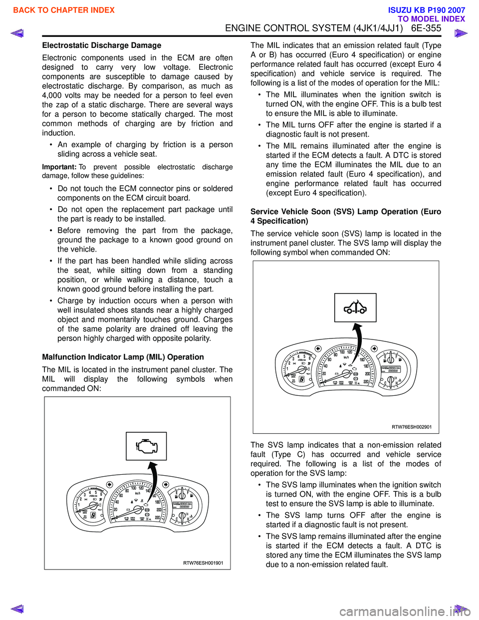
Malfunction Indicator Lamp (MIL) Operation
The MIL is located in the instrument panel cluster. The
MIL will display the following symbols when
commanded ON: The MIL indicates that an emission related fault (Type
A or B) has occurred (Euro 4 specification) or engine
performance related fault has occurred (except Euro 4
specification) and vehicle service is required. The
following is a list of the modes of operation for the MIL:
• The MIL illuminates when the ignition switch is turned ON, with the engine OFF. This is a bulb test
to ensure the MIL is able to illuminate.
• The MIL turns OFF after the engine is started if a diagnostic fault is not present.
• The MIL remains illuminated after the engine is started if the ECM detects a fault. A DTC is stored
any time the ECM illuminates the MIL due to an
emission related fault (Euro 4 specification), and
engine performance related fault has occurred
(except Euro 4 specification).
Service Vehicle Soon (SVS) Lamp Operation (Euro
4 Specification)
The service vehicle soon (SVS) lamp is located in the
instrument panel cluster. The SVS lamp will display the
following symbol when commanded ON:
The SVS lamp indicates that a non-emission related
fault (Type C) has occurred and vehicle service
required. The following is a list of the modes of
operation for the SVS lamp:
• The SVS lamp illuminates when the ignition switch is turned ON, with the engine OFF. This is a bulb
test to ensure the SVS lamp is able to illuminate.
• The SVS lamp turns OFF after the engine is started if a diagnostic fault is not present.
• The SVS lamp remains illuminated after the engine is started if the ECM detects a fault. A DTC is
stored any time the ECM illuminates the SVS lamp
due to a non-emission related fault.
RTW76ESH001901
RTW76ESH002901
BACK TO CHAPTER INDEX
TO MODEL INDEX
ISUZU KB P190 2007
Page 2001 of 6020
ENGINE DIAGNOSIS (C24SE) 6-1
SECTION 6
ENGINE DIAGNOSIS
TABLE OF CONTENTS
PAGE
Engine Diagnosis .............................................................................................................. 6- 2
Hard Starting ................................................................................................................. 6- 2
Engine Compression Test Procedure ......................................................................... 6- 3
Rough Engine Idling or Engine Stalling...................................................................... 6- 4
Rough Engine Running ................................................................................................ 6- 5
Hesitation ..................................................................................................................... . 6- 6
Engine Lacks Power ..................................................................................................... 6- 7
Engine Noisy ................................................................................................................. 6 - 8
Abnormal Noise Due to Hydraulic Lash Adjustor ...................................................... 6- 9
Troubleshooting Procedure ......................................................................................... 6- 9
Abnormal Combustion ................................................................................................. 6-11
Engine Oil Consumption Excessive............................................................................ 6-12
Fuel Consumption Excessive ...................................................................................... 6-13
Oil Problems.................................................................................................................. 6-13
Engine Oil Pressure Check .......................................................................................... 6-13
Malfunction Indicator Lamp ......................................................................................... 6-14
BACK TO CHAPTER INDEX
TO MODEL INDEX
ISUZU KB P190 2007
Page 2014 of 6020

6-14 ENGINE DIAGNOSIS (C24SE)
Malfunction Indicator Lamp
The instrument panel "CHECK ENGINE" Malfunction
Indicator lamp (MIL) illuminates by self diagnostic
system when the system checks the starting of
engine, or senses malfunctions.
Condition Possible cause Correction
"CHECK ENGINE" MIL does not
illuminate at the starting of engine Bulb defective Replace
MIL circuit open Correct or replace
Command signal circuit to operate
self diagnostic system shorted Correct or replace
Engine Control Module (ECM)
cable loosely connected,
disconnected or defective Correct or replace
ECM
defective Replace
“CHECK ENGINE” MIL
illuminates, and stays on Deterioration heated oxygen
sensor of internal element Replace
Heated oxygen sensor connector
terminal improper contact
(If applicable) Reconnect properly
Heated oxygen sensor lead wire
shorted (If applicable) Correct
Heated oxygen sensor circuit
open (If applicable) Correct or replace
Deterioration engine coolant
temperature sensor of internal
element Replace
Engine coolant temperature
sensor connector terminal
improper contact Reconnect properly
Engine coolant temperature
sensor lead wire shorted Correct
Engine coolant temperature
sensor circuit open Correct or replace
Throttle position sensor open or
shorted circuits Correct or replace
Deterioration of crankshaft
position sensor Replace
Crankshaft position sensor circuit
open or shorted Correct or replace
Vehicle speed sensor circuit open Correct or replace
Manifold absolute pressure sensor
circuit open or shorted Correct or replace
Intake air temperature sensor
circuit open or shorted Correct or replace
Fuel injector circuit open or shorted Correct or replace
ECM driver transistor defective Replace EPROM or ECM
Malfunctioning of ECM RAM
(Random Access Memory) or
Malfunctioning of ECM PROM
(Programmed Read Only Memory) Replace EPROM or ECM
BACK TO CHAPTER INDEX
TO MODEL INDEX
ISUZU KB P190 2007
Page 2154 of 6020
6D3-6 STARTING AND CHARGING SYSTEM
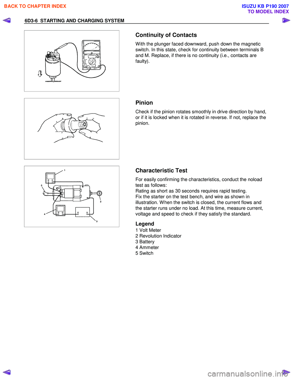
Continuity of Contacts
W ith the plunger faced downward, push down the magnetic
switch. In this state, check for continuity between terminals B
and M. Replace, if there is no continuity (i.e., contacts are
faulty).
Pinion
Check if the pinion rotates smoothly in drive direction by hand,
or if it is locked when it is rotated in reverse. If not, replace the
pinion.
Characteristic Test
For easily confirming the characteristics, conduct the noload
test as follows:
Rating as short as 30 seconds requires rapid testing.
Fix the starter on the test bench, and wire as shown in
illustration. W hen the switch is closed, the current flows and
the starter runs under no load. At this time, measure current,
voltage and speed to check if they satisfy the standard.
Legend
1 Volt Meter
2 Revolution Indicator
3 Battery
4 Ammeter
5 Switch
BACK TO CHAPTER INDEX
TO MODEL INDEX
ISUZU KB P190 2007
Page 2167 of 6020

STARTING AND CHARGING SYSTEM 6D3-19
Inspection
Generator
Before any in field testing can be undertaken it is important
that the battery's conditions is established and the terminals
are clean and tight.
Check the condition of the generator drive belt and ensure that
it is adjusted in accordance with the engine manufacturer's
recommnedations.
Battery conditions:
Note: This assessment may be difficult with maintenance free
assemblies.
Test the specific gravity of the individual cells the readings
should be within 10 points of each other, it is recommended
that the average SG should be 1.260 or higher.
A load test should be carried out to determine the ability of the
battery to supply and accept current. This is a good indicator
as to the general condition of the battery.
A load equal to the normal starting current should be placed
across the battery, the duration of this load test should not
exceed 10 seconds, during this time the terminal voltage
across the battery should not drop below 9.6 volts. Observe
each cell for signs of excessive gas liberation, usuall an
indication of cell failure.
If the battery test is clear proceed with the Generator tests as
follows.
Care should be taken when making the following connections.
It is recommended that the battery negative terminal be
disconnected before the test meters are connected, and
reconnecting the negative terminal when the meters are
inserted into the circuit under test. The warning lamp in the D+
circuit should not exceed 2 watts.
Regulating voltage test on the vehicle.
Connect a voltmeter to the generator, the positive lead to the
B+ terminal and the nagative lead to the generator casing.
Select the voltage range to suit the system, i.e. 20v for 12 volt
sysytems or 40v for 24 volt systems. Connect an ammeter in
series with the main output cable from the B+ terminal on the
generator, the range selected must be capable of reading the
maximum output from the generator.
Note the voltmeter reading before starting the engine. This
reading should increase when the engine is running indicating
generator output, start the engine and increase the engine
speed until the generator is running at 4000 rpm, switch on
vehicle loads of 5-10 A is indcated on the ammeter, the
voltmeter shoud read 14.0-14.2 v for a 12 volt system, for a 24
volt system the readings should be 5-10 A and 27.7-28.5 volts.
BACK TO CHAPTER INDEX
TO MODEL INDEX
ISUZU KB P190 2007
Page 2174 of 6020

6E–4 ENGINE DRIVEABILITY AND EMISSIONS
DIAGNOSTIC TROUBLE CODE (DTC) P0443 EVAPORATIVE (EVAP) EMISSION CONTROL
SYSTEM PURGE CONTROL CIRCUIT ..... 6E-191
Circuit Description ..................................... 6E-191
Diagnostic Aids .......................................... 6E-191
Diagnostic Trouble Code (DTC) P0443 EVAP Emission Control System Purge
Control Circuit .......................................... 6E-192
DIAGNOSTIC TROUBLE CODE (DTC) P0502 VEHICLE SPEED SENSOR (VSS) CIRCUIT
LOW INPUT ................................................ 6E-195
Circuit Description ..................................... 6E-195
Diagnostic Aids .......................................... 6E-195
Diagnostic Trouble Code (DTC) P0502 Vehicle Speed Sensor Circuit Low Input . 6E-196
DIAGNOSTIC TROUBLE CODE (DTC) P0562 SYSTEM VOLTAGE LOW .......................... 6E-202
Circuit Description ..................................... 6E-202
Diagnostic Aids .......................................... 6E-202
Diagnostic Trouble Code (DTC) P0562 System Voltage Low ............................................. 6E-202
DIAGNOSTIC TROUBLE CODE (DTC) P0563 SYSTEM VOLTAGE HIGH ......................... 6E-204
Circuit Description ..................................... 6E-204
Diagnostic Aids .......................................... 6E-204
Diagnostic Trouble Code (DTC) P0563 System Voltage High ............................................ 6E-204
DIAGNOSTIC TROUBLE CODE (DTC) P0601 ECM MEMORY CHECKSUM ..................... 6E-206
Circuit Description ..................................... 6E-206
Diagnostic Aids .......................................... 6E-206
Diagnostic Trouble Code (DTC) P0601 ECM Memory Checksum .................................. 6E-206
DIAGNOSTIC TROUBLE CODE (DTC) P0602 ECU PROGRAMMING ERROR ................. 6E-207
Circuit Description ..................................... 6E-207
Diagnostic Aids .......................................... 6E-207
Diagnostic Trouble Code (DTC) P0602 ECU Programming Error .................................. 6E-207
DTC P0650 MALFUNCTION INDICATOR LAMP (MIL) CONTOROL CIRCUIT MALFUNCTION 6E-208
Circuit Description ..................................... 6E-208
Diagnostic Aids .......................................... 6E-208
Diagnostic Trouble Code (DTC) P0650 Malfunction Indicator Lamp (MIL) Control
Circuit Malfunction ................................... 6E-209
DIAGNOSTIC TROUBLE CODE (DTC) P1167 FUEL SUPPLY SYSTEM RICH DURING
DECELERATION FUEL CUT OFF ............. 6E-211
Circuit Description ..................................... 6E-211
Diagnostic Aids .......................................... 6E-211
Diagnostic Trouble Code (DTC) P1167 Fuel Supply System Rich During
Deceleration Fuel Cutoff .......................... 6E-212
DIAGNOSTIC TROUBLE CODE (DTC) P1171 FUEL SUPPLY SYSTEM LEAN DURING
POWER ENRICHMENT ............................. 6E-214
Circuit Description ...................................... 6E-214
Diagnostic Aids .......................................... 6E-215
Diagnostic Trouble Code (DTC) P1171 Fuel Supply System Lean During Power
Enrichment .............................................. 6E-215
DIAGNOSTIC TROUBLE CODE (DTC) P1625 ECM SYSTEM RESET ............................... 6E-217
Circuit Description ...................................... 6E-217
Diagnostic Aids .......................................... 6E-217
Diagnostic Trouble Code (DTC) P1625 ECM System Reset .......................................... 6E-217
DIAGNOSTIC TROUBLE CODE (DTC) P1626 IMMOBILIZER NO SIGNAL ........................ 6E-218
Circuit Description ...................................... 6E-218
Diagnostic Aids .......................................... 6E-218
Diagnostic Trouble Code (DTC) P1626 Immobilizer No Signal .............................. 6E-219
DIAGNOSTIC TROUBLE CODE (DTC) P1631 IMMOBILIZER WRONG SIGNAL ............... 6E-222
Circuit Description ...................................... 6E-222
Diagnostic Aids .......................................... 6E-222
Diagnostic Trouble Code (DTC) P1631 Immobilizer Wrong Signal ........................ 6E-223
DIAGNOSTIC TROUBLE CODE (DTC) P1648 WRONG SECURITY CODE ENTERED .. 6E-224
Circuit Description ...................................... 6E-224
Diagnostic Aids .......................................... 6E-224
Diagnostic Trouble Code (DTC) P1648 Wrong Security Code Entered ............................ 6E-225
DIAGNOSTIC TROUBLE CODE (DTC) P1649 IMMOBILIZER FUNCTION NOT
PROGRAMMED ......................................... 6E-226
Circuit Description ...................................... 6E-226
Diagnostic Aids .......................................... 6E-226
Diagnostic Trouble Code (DTC) P1649 Immobilizer Function Not Programmed ... 6E-227
DIAGNOSTIC TROUBLE CODE (DTC) P1693 TACHOMETER OUTPUT LOW VOLTAGE 6E-228
Circuit Description ...................................... 6E-228
Diagnostic Aids .......................................... 6E-228
Diagnostic Trouble Code (DTC) P1693 Tachometer Output Low Voltage ............. 6E-229
SYMPTOM DIAGNOSIS ............................... 6E-232
PRELIMINARY CHECKS ............................. 6E-232
VISUAL/PHYSICAL CHECK ......................... 6E-232
INTERMITTENT ........................................... 6E-232
BACK TO CHAPTER INDEX
TO MODEL INDEX
ISUZU KB P190 2007